Table of Contents
Advertisement
Available languages
Available languages
Owner's
uai
CRRFrSMRH
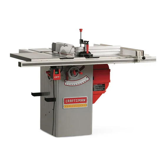
1.75 Horsepower
(continuous
duty)
2.4 Horsepower
(maximum
developed)
3450 R.P.M. (no load R.P.M.)
10-in. TABLE SAW
Model
No.
152.221240
CAUTION:
FOR YOUR OWN SAFETY;
Read
and follow all of the Safety and
Operating
Instructions
before
Operating
this Table Saw.
Customer Helpline
1-800-897-7709
Please have your Model No.
and Serial No. available.
Sears, Roebuck
and Co., Hoffman
Estates,
IL 60179 U.S.A.
Part No. OR91552
Revision:
D
Espa5ol
pg. 48
Advertisement
Table of Contents

Related Manuals for Craftsman 22124 - Professional 10 in. Table Saw


Summary of Contents for Craftsman 22124 - Professional 10 in. Table Saw
- Page 1 Owner's CRRFrSMRH 1.75 Horsepower (continuous duty) 2.4 Horsepower (maximum developed) 3450 R.P.M. (no load R.P.M.) 10-in. TABLE SAW Model 152.221240 Customer Helpline CAUTION: 1-800-897-7709 FOR YOUR OWN SAFETY; Read and follow all of the Safety and Please have your Model No. Operating Instructions before...
-
Page 2: Specifications
SECTION PAGE Warranty ..................................Product Specifications ..............................Glossary of Terms ................................Safety Instructions ................................. Guidelines for Extension Cords ........................... Grounding Instructions ..............................Specific Safety Instructions for Table Saw ........................Accessories and Attachments ............................Carton Contents ................................Know Your Table Saw ..............................Assembly Instructions .............................. - Page 3 Anti-Kickback F ingers - Asafety device attached t othe Kerf- Thematerial removed b ytheblade inthework- blade guard andsplitter a ssembly designed t ostopa piece during anycutting operation. workpiece frombeing thrown backduring a cutting opera- tion. Kickback - When theworkpiece is thrown back towards theoperator during a cutting operation when theworkpiece Arbor- Theshaft o nwhich theblade or accessory cut- initially c ontacts t heblade orif theworkpiece pinches t he...
- Page 4 GENERAL SAFETY iNSTRUCTiONS ALWAYS WEAR EYE PROTECTION. Any power tool can throw debris into the eyes during opera- Operating a Table Saw can be dangerous if safety and tions, which could cause severe and permanent common sense are ignored. The operator must be eye damage.
-
Page 5: Guidelines For Extension Cords
20. EACH GUIDELINES AND EVERY TIME, CHECK FOR DAM= AGED PARTS PRIOR TO USING THE TOOL. EXTENSION CORDS Carefully check all guards to see that they operate properly, are not damaged, and perform their The smaller the gauge-number, the larger diameter of intended functions. -
Page 6: Grounding Instructions
USE ONLY A 3=WIRE EXTENSION CORD THAT HAS THiS TOOL MUST BE GROUNDED WHILE iN USE A 3=PRONG GROUNDING PLUG AND A 3-POLE TO PROTECT THE OPERATOR FROM ELECTRIC RECEPTACLE THAT ACCEPTS THE TOOL'S PLUG. SHOCK. REPLACE A DAMAGED OR WORN CORD IMMEDI= iN THE EVENT OF A MALFUNCTION OR BREAK- ATELY. -
Page 7: Safety Instructions
It is also necessary to replace the 120 volt plug, sup- MAKE CERTAIN that masks or respirators are plied with the motor, with a UL/CSA Listed plug suitable MSHA/NIOSH approved. for 240 volts and rated current of the saw. Contact a The operation of any Table Saw can result in debris local qualified electrician for proper procedures to install being thrown into your eyes, which can result in severe... - Page 8 14. TheTable Sawis designed f orhomeuseor light 27. NEVER perform layout, a ssembly orset-upworkon commercial dutyONLY. thetable/work a reawhenthemachine is running. 28. NEVER resetthethermal-overload buttonbefore 15. CONNECT T able Sawtoa properly grounded o utlet only. S eegrounding instructions. youhaveturned thetablesaw"OFF". 16.
- Page 9 AVAILABLE ACCESSORIES Sears may recommend other accessories not listed in this manual. Visit your Sears Hardware Department or see the Sears See your nearest Sears Hardware Department or Sears Power and Hand Tool Catalog for the following acces- sories. Power and Hand Tool Catalog for other accessories. ITEM Do not use any accessory unless you have completely STOCK...
- Page 10 CONSTRUCTING A PUSHSTICK When ripping work less than 4 inches wide, a pushstick should be used to complete the feed and could easily be made from scrap material by following the pattern shown in figure 2C. Fig. 2C The Pushstick should be made of 3/4 or 1/2 inch wood or a thickness less than the width of the workpiece to be cut.
- Page 11 UNPACKING AND CHECKING CONTENTS Fig. 3-1 The table saw is a heavy machine, two people are required to unpack and lift the table saw. This table saw will require some amount of assembly. This table saw is shipped in two separate cartons, one for the saw and one for the fence.
- Page 12 FENCE Fig. 3-2 20. Rearrail 21. Frontrail 22. Guidetube 23. Extension t ableassembly 24. T-Square _) fenceassembly 25. Locking handle knob 26. Cursor ( 2) 27. Template Fig. 3-3 MITER GAUGE 40. Miter gauge 41. Cross cut fence 42. Depth stop 43.
- Page 13 Fig. 3=4 OUTFEED TABLE 50. Outfeed table assembly 51. Hinge assembly (2) 52. Clamp knob 53. Upper support assembly 54. Lower support 55. Support retainer Hardware packs are not identified or labeled. See hardware diagram to help in finding the correct part. See figure 3-5. , Hardware Pack for Biesemeyer Fence Rails...
- Page 14 Fig. 3=5 HEAD SCREW N8xI.25 x 25_M HEAD _REW MSx|.25 x 3O_a HEX NUT M6, HEX NUT N8×1.25 NYLOCK HEAD SCREW 5/|6-|8 × |-i/2" HEX NUT M5 HEX HEAD SCREW N6 x 25_ HEX Nut 5/16°=18 HEX HEAD SCREW N6 x 35_ FLAT WASHER HEX HEAD...
- Page 15 17. Rip fence holder bracket 1. Splitter assembly 9. Biesemeyer commercial T-square fence 2. Anti-kickback fingers 10. Accessory Biesemeyer extension table 18. Blade height handwheel 3. Blade 11. Front rail with scale 19. Handwheel lock 4. Blade guard 12. Rip fence handle 20.
- Page 16 TOOLS REQUIRED NOTE: If you will be permanently attaching your table saw to the floor, DO NOT assemble leveling feet and go The following tools are needed for assembly and align- on to the next step. ment. Note: Two blade wrenches and five hex wrenches are provided with your table saw.
- Page 17 POLY=V BELT ASSEMBLY CAUTION: The extension wings are heavy; two people are required to assemble both extension wings to the table saw. MAKE CERTAIN the table saw is disconnected from Assemble one of the extension wings (A) to the left the power source.
- Page 18 BLADE GUARD AND SPLITTER ASSEMBLY Place one of the handwheels (A) onto the bevel shaft (B) located on the side of the cabinet. Align the groove (C) in the back of the handwheel with the pin (D). See figure 8-1. MAKE CERTAIN the table saw is disconnected from the power source.
- Page 19 Figure 10=3 Figure 10=5 \\\\\ Place the front attachment point (D) of the blade Place a square (N) onto the saw table and against guard and splitter assembly (H) down into the the splitter assembly (0) behind the kickback fin- tool-less front attachment point (E).
- Page 20 ® SEMEYER BIESEMEYER ® T=SQUARE ® COMMERCIAL RiP FENCE SYSTEM ASSEMBLY SAW TABLE FRONT AND REAR RAiL ASSEMBLY FRONT MAKE CERTAIN the table saw is disconnected from Using the template (G), check and adjust front rail the power source. parallel to the table surface on both sides of the saw table.
- Page 21 IMPORTANT: Donotusetemplate supplied tosetthe GUIDE TUBE AND SWITCH ASSEMBLY rearrail. Figure 11=7 8. Makesurethetopedgeof thefrontrailis belowthe topofthesawtableandthatthefrontrailis not blocking theendsof themitergaugegrooves. 9. Whenyouaresurethattherearrailis properly aligned andit is parallel to thetablesurface, securely tightenrearrailmounting hardware. BIESEMEYER EXTENSION TABLE ASSEMBLY Figure 11=6 Align the four threaded holes in the bottom of the guide tube (A) with the four holes in the right side of the front rail (B).
- Page 22 KNOB AND CURSOR ASSEMBLY OUTFEED TABLE ASSEMBLY Figure 11=10 Figure 11=9 Thread knob (A) onto fence locking handle (B). Turn knob clockwise to screw it onto threads of fence locking handle. See figure 11-9. Align left fence side (C) at a distance from the right side (D) of the right miter gauge groove and lock the fence.
- Page 23 CONNECTING SWITCH CORD Fold out lower and upper support arms straight, so that the pin (G) in the upper support goes into notch TO MOTOR CORD (H) of lower support and securely tighten clamp knob. MAKE CERTAIN the table saw is disconnected from Assemble both hinge assemblies (I) to the outfeed the power source.
- Page 24 MITER GAUGE ASSEMBLY Figure 13=2 MAKE CERTAIN the table saw is disconnected from the power source. Figure 13-1 Slide both of the square nuts with hex socket head screw and flat washer (F) into the lower T-slot (G) of the cross cut fence (H). See figure 13-2. Place the thread section of the hex socket head screws into the grooves (I) of the miter gauge body.
- Page 25 Move the table saw out of the way and drill pilot Open the motor cover (F) and remove the two holes at the four locations marked. Phillip head screws (G) from the CRAFTSMAN 10. Attach the table saw to the floor using appropriate nameplate (H). NOTE: These two Phillip head hardware (not included).
- Page 26 CAUTION LOCKING ON/OFF SWITCH • A separate electrical circuit should be used for your When the table saw is not in use, the "ON" button should be locked so that it cannot be started. table saw. The table saw comes pre-wired for 120-volt use.
- Page 27 Tolower thesawblade,loosen thehandwheel lock If the blade will not tilt to 90-degrees, turn (counter- knob(counterclockwise) andturnthe handwheel clockwise) the set screw (C) in the left hand side of counterclockwise. Whenthesawbladeisat itsdesired the saw table until the blade can be positioned to height, t ighten thehandwheel lockknob(clockwise) 90-degrees.
- Page 28 Raise the saw blade to its highest point. Figure 17=1 Place a combination square (A) on the saw table with one edge (B) of the square against the left miter slot (C). See figure 17A-1. Adjust the square so the rule (D) just touches the saw blade about 1 inch in from the outer diameter.
- Page 29 Fig. 17B=1 ® BIESEMEYER BIESEMEYER ® T=SQUARE ® COMMERCIAL RiP FENCE SYSTEM ASSEMBLY OPERATIONS AND ADJUSTMENTS MAKE CERTAIN the table saw is disconnected from the power source when making adjustments. Figure 18=1 To align the blade parallel to the miter slot, first loosen two hex head screws (A) under the left side of the table saw.
- Page 30 FENCE ALIGNMENT Slightly tighten the two adjusting screws (I), using a 3/16" hex wrench (not supplied). NOTE: Screws should be tightened an equal amount. The rip fence (A) must be adjusted so it is parallel See figure 18-2. to the miter gauge groove (G). See figure 18-1. To check and adjust, move fence until the bottom Replace rip fence onto the guide tube and lock.
- Page 31 4. Oncetheinsertis level,secure theinsert w iththe Replace junction box cover and close motor cover. retaining boltremoved instep1. Replace 120 volt plug with a UL/CSA Listed 240 5. Thetableinsertis equipped witha fingerhole(E) volt plug rated for current of the motor. foreasyremoval. Seefigure19-1. The ON/OFF switch is 4-pole and does not need modified.
- Page 32 ALiGNiNG SPLITTER BRACKET Retighten the two hex socket head cap screws after the splitter has been aligned. If necessary, adjust the rear splitter bracket (F). MAKE CERTAIN the table saw is disconnected from Make certain that entire splitter is in line with the saw blade.
- Page 33 Figure 22=2 CLAMP AND FENCE STOP OPERATION MAKE CERTAIN the table saw is disconnected from the power source when making adjustments. Figure 23=1 To rotate to the next positive stop pull plunger out, rotate miter gauge body then push plunger back in and continue rotating miter gauge body until it stops against next positive stop.
- Page 34 24=2 Crosscutting requires the use of the miter gauge (A) to position and guide the workpiece (B). See figure 24-1. The use of non-Craftsman attachments and acces- sories may result in risk of injury or damage to the table saw.
-
Page 35: Accessories And Attachments
Ripping is the operation of making a cut with the grain of the workpiece; the rip fence (A) is used to position An accessory Craftsman Fence Guide can be pur- and guide the workpiece. Since the workpiece is chased to assist when making narrow cuts. See pushed along the fence, it must have a straight edge "ACCESSORIES... - Page 36 DADO BLADE Dado blades and chippers have a set to their teeth. The teeth of the dado blades and chippers must be arranged so that the set of each tooth overlaps the next tooth. The set of the dado blade (C) and chipper (D) The blade guard and splitter assembly cannot be used overlap as shown in Figure 26-3.
- Page 37 Figure 26=5 • The blade guard and splitter assembly cannot be used when dadoing or molding and must be swung to the rear of the saw. Blade guard must be reassem- bled when finished. Figure 27=2 Figure 26-5, shows a typical dado operation using the miter gauge.
- Page 38 Position thewoodfacingoverthecutterhead w iththe CAUTION cutterhead b elowthesurface ofthetable. Turnthesaw When molding end grain, the miter gauge must be onandraisethecutterhead s lowly.Thecutterhead w ill used. The feed should be slowed up at the end of cutitsowngroove inthewoodfacing. the cut to prevent splintering In all cuts, pay attention to the grain, making the cuts in the same direction as the grain whenever possible.
- Page 39 LUBRiCATiON The table saw has sealed lubricated bearings in the Only trained personnel should perform repairs to the motor housing that do not require any additional lubrica- table saw. Contact your nearest Sears Service Center tion from the operator. for authorized service. Unauthorized repairs or replace- ment with non-factory parts could cause serious injury to the operator and damage to the table saw.
- Page 40 TOPREVENT I NJURY TO YOURSELF or damage to the table saw, turn the power switch to the "OFF" position and unplug the power cord from the electrical receptacle before making any adjustments. PROBLEM LIKELY CAUSE(S) SOLUTION Motor does not Switch not pressed in far enough or switch Depress switch in 1/2 inch or make sure switch is in the start: in the "OFF"...
- Page 41 10-IN. T ABLE MODEL NO.152.221240 When servicing, use only CRAFTSMAN replacement parts. Use of any other parts may create a HAZARD or cause product damage. Any attempt to repair or replace electrical parts on this table saw may create a HAZARD unless a qualified service technician does repairs.
- Page 42 10-iN.TABLE MODEL NO.152.221240 PART No. Description Qty. Key No. PART No. Description Qty. OR90059 FLAT WASHER M6 OR91134 WRENCH HOOK OR91826 CHEESE HEAD SCREW M6 x 16ram OR91135 FENCE HOOK OR91804 OR91832 TRIANGLE TAP SCREW M4 x 8ram HANDWHEEL ASSEMBLY, (NOT SHOWN) 329A OR91832...
- Page 43 > 39A ( i<2>...
- Page 44 F"...
- Page 45 > 3°2l ,$303(3) I:l_ _°'- 301B 304A PI_P|I|II|, r"...
- Page 46 10-iN. TABLE SAW MODEL NO.152.221240 564(2) 365(1 366(8) 367(8) Z,36,3(8) 355(2)
- Page 47 1O-IN. T ABLE MODEL NO.152.221240 40 t .-"_---42 t (2) 4.32(3)
- Page 48 _nuai dei Proprietario CRRFrSMRH 1.75 caballos de fuerza (servicio continuo) 2.4 caballos de fuerza (maximo desarrollado) 3450 R.P.IVI. (R.P.M. sin carga) de 1 No. de IVIodelo 152.221240 Linea de Ayudaal Cliente PRECAUCION: 1-800-897-7709 PARA SU SEGURIDAD PERSONAL: Sirvase tener listo su Lea y obedezca todas las Instrucciones No de Modelo y No.
- Page 49 SECCION PAGINA Garant[a ....................................... Especificacienes del producto ................................Glesario de terminos ................................... Instrucciones de seguridad ................................. Directrices para las extensiones electricas ............................Instrucciones de conexi6n a tierra ..............................Instrucciones especfficas de seguridad para las sierras de mesa ..................... Accesorios y aditamentos ...................................
- Page 50 Alefriz - Muesca cuadrada en el borde del material. Fresa rotativa de ranurar - Corte no directo que produce una muesca cuadrada. Una fresa rotativa tiene, tfpicamente, un ancho de 1/8 a 13/16 pulg. Una fresa rotativa requiere un Contragolpe - Cuando el material es arrojado hacia el conjunte especial de hojas que no estan incluidas con esta operario durante una operaci6n de corte en el memento que...
- Page 51 INSTRUCCIONES GENERALES UTILICE PROTECCION OCULAR SIEMPRE. Cualquier herramienta mecb,nica puede arrojar escombros hacia los SEGURiDAD ojos durante el funcionamiento, pudiendo esto resultar en El funcionamiento de una Sierra de Mesa puede resultar heridas oculares graves y permanentes. Los anteojos de peligroso si se hace caso omiso de la seguridad y del sentido uso cotidiano NO son gafas de seguridad.
- Page 52 20. REVISE SI HAY PiEZAS DAIklADAS ANTES DE CADA DIRECTRICES PARA USO DE LA HERRAMIENTA. Revise todos los protec- LAS EXTENSIONES ELC:CTRICAS tors cuidadosamente para comprobar que funcionan correctamente y que no estan dahados, y que realizan Mientras menor sea el n0mero de calibre, mayor sera el sus funciones dise_adas correctamente.
- Page 53 REPONGA CUALQUIER CORDON DAI_IADO O GASTADO ESTA HERRAMIENTA DEBE ESTAR CONECTADA A TIER- RA DURANTE EL USO PARA PROTEGER AL OPERARIO INMEDIATAMENTE. CONTRA LOS CHOQUES ELE_CTRICOS. PARA LAS MAQUINAS CONECTADAS A TIERRA Y CON CORDON DISEI_IADAS PARA EL USO EN UN CIRCUITO EN EL CASO DE UN MALFUNCIONAMIENTO O AVERIA, la DE SUMINJSTRO CON UNA POTENCIA DE RFtGIMEN...
- Page 54 ASEGURESE de que las mascaras o respiradores tienen Tambien serA necesario reemplazar el enchufe de 120 voltios suministrado con el motor por un enchufe clasificado por aprobaci6n MSHA / NIOSH. UL/CSA come apropiado para los 240 voltios y la corriente clasificada de la sierra.
- Page 55 JAMAS realice labores de trazado, ensamblado o monta- 14. La Sierra de Mesa esta diseRada para el use dom4stico o el use comercial ligero SOLAMENTE. je sobre la mesa / zona de trabajo cuando la m_quina se encuentre en funcionamiento. 15.
- Page 56 ACCESORIOS DiSPONiBLES Sears podra recomendar otros accesorios no listados en este manual. Visite su Departamento de Ferreteffa de Sears o consulte el Consulte su Departamento de Ferreteffa de Sears mas cer- Catalogo de Herramientas Electricas y de Mano de Sears cano o el Catalogo de Herramientas Electricas y de Mano de para los siguientes accesorios:...
- Page 57 CONSTRUYENDO UNA VARA DE EMPUJE Durante el corte a Io largo de materiales con menos de 4 pulgadas de ancho, se debe hacer uso de una vara de empuje para completar la alimentaci6n. Puede construirse facilmente utilizando material descartado y siguiendo el patr6n ilustrado en la Figura 2C.
- Page 58 DESEMPACANDO Y REVISANDO Figura EL CONTENIDO La sierra de mesa es una maquina pesada. Se requieren dos personas para desempaquetarla y levantar la sierra de mesa. Esta sierra de mesa requerira cierta cantidad de ensamblado. Esta sierra de mesa se env[a en dos cajas individuales, para la sierra y otra para la gu(a.
- Page 59 GUiA Figura. 20. Riel posterior 21. Riel delantero 22. Tubo de gufa 23. Ensamblado de extensi6n de mesa 24. Ensamblado de la gufa de la escuadra en T 25. Perilla de la agarradera de cierre 26. Cursor (2) 27. Plantilla ESCUADRA DE INGLETES Figura...
- Page 60 MESA DE AVANCE DE SALIDA Figura. 50. Ensamblado de la mesa de avance de salida 51. Ensamblado de bisagras (2) 52. Perilla de abrazadera 53. Ensamblado de soporte superior 54. Soporte inferior 55. Reten del soporte Los estuches de ferreter[a no estan identificados ni etiquetados.
- Page 61 Fig. 3-5 © TORNILLO DE CABEZA HEX M8 x 1.25 x 25 mm TORNILLO DE CABEZA HE× M8 x 1.25 x 30 mm ©El TUERCA HEX M8 x 1.25 TUERCA HEX M6, T©RNILL© DE CABEZA HEX 5/16-18 x 1-1/2 pulg. NYLOCK ©El ©...
- Page 62 1. Ensamblado del hendidor 13. Cubierta del motor 14. Escuadra de biselado 2. Dedos anticontragolpe 3. Hoja 15. Gabinete completo 16. Pie nivelador 4. Protector de hoja 5. Pieza inserta de alineamiento de corte 17. Soporte de sujeci6n de la gufa de corte a Io largo 6.
- Page 63 HERRAIVilENTAS REQUERIDAS AVlSO: Siva a afianzar su sierra de mesa al suelo perma- nentemente, NO ENSAMBLE las patas niveladoras y prosiga Se requieren las siguientes herramientas para el montaje y el al siguiente paso. alineamiento. Aviso: Se suministran dos Ilaves de hoja y cinco Ilaves hexagonales con su sierra de mesa.
- Page 64 MONTAJE DE LA CORREA POLY-V PRECAUCION: Las alas de extensi6n son pesadas. Se requieren dos personas para ensamblar ambas alas de extensi6n a la sierra de mesa. Monte una de las alas de extensi6n (A) al lade izquierdo ASEGORESE de que la sierra de mesa este desconectada de la sierra de mesa.
- Page 65 MONTAJE DEL PROTECTOR Coloque uno de los volantes de mane (A) sobre el eje biselado (B) Iocalizado en el lado del gabinete. La ranura HOJAS Y HENDIDOR (C) en el dorso del volante debe alinearse con el pasador (D). Ver la figura 8-1. Figura ASEGURESE de que la sierra de mesa este desconectada...
- Page 66 Figura 10=3 Figura 10=5 Coloque el punto de conexi6n delantero (D) del ensam- Coloque una escuadra (N) sobre la mesa de la sterra y blado de protector de hoja y de hendidor (H) sobre el contra el ensamblado del hendidor (O) detras de los punto de conexi6n delantero que carece de herramientas dedos anticontragolpe (P).
- Page 67 Figura 11-3 ® SEMEYER ENSAMBLADO DEL SISTEMA COMERCIAL DE GUiA DE CORTE A LO LARGO MESA DE LA ESCUADRA "T" DE BIESEMEYER SIERRA RIEL MONTAJE DE LOS RIELES DELANTERO DELANTERO TRASERO Usando la plantilla (G), revise y ajuste el riel delantero ASEGURESE de que la mesa este desconectada de la paralelo con la superficie de la mesa en ambos lades de...
- Page 68 ENSAMBLADO DEL TUBO DE GUiA IMPORTANTE: No utilice la plantilla suministrada para fijar el riel trasero. Y CONMUTADOR Aseg0rese de que el borde superior del riel delantero Figura 11-7 este por debajo de la parte superior de la mesa de la sierra y que el riel delantero no este bloqueando los extremos de las ranuras de la escuadra de ingletes.
- Page 69 ENSAMBLADO DE LA PERILLA Y CURSOR ENSAMBLADO DE LA MESA DE AVANCE DE SALIDA Figura 11=9 Figura 11=10 Enrosque la perilla (A) sobre la agarradera de cierre de la guia (B). Gire la perilla en sentido horario para atornillarla sobre las roscas de la agarradera de cierre de la guia.
- Page 70 CONECTANDO EL CORDON Desdoble los brazos de soporte inferior y superior hasta dejarlos rectos, de manera que el pasador (G) en el INTERRUPTOR AL CORD(_N DEL MOTOR soporte superior pueda insertarse en la muesca (H) del soporte inferior, y afiance la perilla de abrazadera seguramente.
- Page 71 MONTAJE DE LA ESCUADRA Figura 13-2 INGLETES ASEGORESE de que la sierra de mesa este desconectada de la fuente de energfa. Figura 13-1 Coloque la secci6n roscada de los tornillos de cabeza hueca hexagonal en las ranuras (I) del cuerpo de la escuadra de ingletes.
- Page 72 EMPERNANDO LA SIERRA DE MESA FIgura 13A-3 AL PISO ASEGURESE de que la sierra de mesa este desconectada de la fuente de energfa. Si Io desea, la sierra de mesa puede montarse al piso de forma permanente. Para conectarla al piso, consulte las siguientes instrucciones: Flgura 13A-1...
- Page 73 PRECAUCI6N ENCLAVANDO EL INTERRUPTOR ENCENDIDO/APAGADO Debe hacerse use de un circuito electrico individual para su sierra de mesa. La sierra de mesa viene cableada Cuando la sierra de mesa no se encuentre en uso, el de antemano para el funcionamiento a 120 voltios.
- Page 74 Para bajar l ahoja delasierra, afloje laperilla decierre del Si la hoja no se inclina a 90 grados, gire el tornillo de volante d emane (ensentido a ntihorario) y gire elvolante d e fijaci6n (C) (en sentido antihorario) al lado izquierdo de la mane ensentido a ntihorario.
- Page 75 Eleve la hoja de la sierra a su punto m&s alto. Figura 17-1 Coloque una escuadra de combinaciones (A) sobre la mesa de la sierra con uno de los bordes (B) de la escuadra contra la ranura de ingletes izquierda (C). Ver figura 17A-1.
- Page 76 Figura 17B=1 ® BIESEMEYER ENSAIVIBLADO DEL SISTEMA COMERClAL DE GUiA DE CORTE A LO LARGO ESCUADRA "T" DE BIESEMEYER OPERACIONES Y AJUSTES ASEGURESE de que la sierra de mesa este desconectada de la fuente de energfa durante la realizaci6n de los ajustes. Figura 18=1 Para alinear el paralelo de la hoja con la ranura de...
- Page 77 ALINEAMIENTO DE LA GU[A Apriete ligeramente los dos tornillos de ajuste (I) usando una Ilave hexagonal de 3/16 pulg. (no suministrada). La gu[a de corte a Io largo (A) debe ajustarse de tal AVlSO: Los tornillos deben afianzarse en cantidades manera que quede paralela con la ranura de la escuadra iguales.
- Page 78 Una vez que la pieza de inserci6n de mesa este nive- Reponga la cubierta de la caja de empalmes y cierre la cubierta del motor. lada, afiance la pieza con el perno de reten que fue removido en el paso 1. Reponga el enchufe de 120 voltios por uno de 240 La pieza de inserci6n de mesa viene equipada con un voltios clasificado por UL/CSA para la corriente del motor.
- Page 79 ALINEANDO EL SOPORTE DEL HENDIDOR Vuelva a apretar los dos tornillos de cabeza hueca hexagonal despues de haber alineado el hendidor. Si resulta necesario, ajuste el soporte del hendidor posterior (F) asegurandose de que el hendidor completo ASEGORESE de que la sierra de mesa este desconectada este en I[nea con la hoja de la sierra.
- Page 80 OPERACION DE LA ABRAZADERA Y DEL Figura 22=2 TOPE DE LA GUiA ASEGURESE de que la sierra de mesa este desconectada de la fuente de energfa cuando realice los ajustes. Figura 23=1 Afloje la tuerca de cierre (D) 3 6 4 vueltas. Ver la figura 22-2.
- Page 81 (A) para posicionar y guiar el material (B). Ver la figura 24-1. El uso de aditamentos y accesorios que no sean de Craftsman podra resultar en el riesgo de lesiones al usuario o dare a la sierra de mesa. Figura...
- Page 82 SlEMPRE mantenga las manos y los dedos alejados de la hoja de la sierra. Figura 25=1 Puede comprarse una Gufa Craftsman de accesorio como ayuda cuando vaya a efectuar cortes angostos. Vea la secci6n "ACCESORIOS Y ADITAMENTOS" en este manual.
- Page 83 CONJUNTO DE FRESAS ROTATIVAS Los dientes de las fresas rotativas y las astilladoras tienen gradaci6n. Los dientes de las fresas rotativas y las astillado- DE RANURAR ras deben estar dispuestas de tal forma que la gradaci6n de cada diente este solapada con la del pr6ximo diente. Las gradaciones de la fresa rotativa (C) y la astilladora (D) se solapan como se ilustra en la Figura 26-3.
- Page 84 Figura 26-5 El protector de hoja y el ensamblado del hendidor no pueden utilizarse durante el fresado o el moldurado y deben bascu- larse hacia la parte trasera de la sierra• El protector de hoja debe reensamblarse cuando haya terminado. Figura 27-2 La Figura 26-5 muestra una operaci6n tfpica de fresado...
- Page 85 PRECAUClON Posicione el refrentado de madera sobre el cabezal de corte con el cabezal de corte per debajo de la superficie de la Durante el moldurado a contrahilo debe hacerse use de la mesa. Encienda la sierra y eleve el cabezal de corte lenta- mente.
- Page 86 LUBRICACK_N La sierra de mesa tiene cojinetes lubricados sellados en la S61o personal competente debe realizar reparaciones a la carcasa del motor que no requieren lubricaci6n adicional per sierra de mesa. Comunfquese con su Centre de Servicio parte del operario. Sears mas cercano para obtener servicio autorizado.
- Page 87 Para evitar herirse a si mismo o daRar la sierra de mesa, conmute el interrupter de energfa a "APAGADO" y desenchufe el cord6n de potencia del tomacorrientes antes de realizar cualquier ajuste. PROBLEMA CAUSAS POSIBLES SOLUCION Motor no arranca: 1. Interruptor no fue oprimido a suficiente profundidad Presione...
- Page 88 Your Home For repair - in your home - of all major brand appliances, ........lawn and garden equipment, or heating and cooling systems, ....no matter who made it, no matter who sold it! For the replacement parts, accessories owner's manuals that you need to do-it-yourself.