Table of Contents
Advertisement
Operator's
Manual
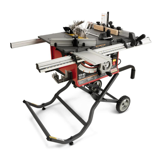
10 in. TABLE SAW
Model No,
315.218290
_k
WARNING: To reduce the risk of injury,the
user must read and understandthe operator's
manual before using this product.
Customer Help Line: 1-800-932-3188
Seam, Roebuck and Co., 3333 BeverPy Rd., Hoffman Estates, IL 60179 USA
Visit the Craftsman web page: www.seam.com!cmffsman
983000-693
7-15-05
Advertisement
Table of Contents

Related Manuals for Craftsman 21829 - Professional 10 in. Portable Table Saw


Summary of Contents for Craftsman 21829 - Professional 10 in. Portable Table Saw
- Page 1 WARNING: To reduce the risk of injury,the user must read and understandthe operator's manual before using this product. Customer Help Line: 1-800-932-3188 Seam, Roebuck and Co., 3333 BeverPy Rd., Hoffman Estates, IL 60179 USA Visit the Craftsman web page: www.seam.com!cmffsman 983000-693 7-15-05...
-
Page 2: Table Of Contents
ONE YEAR FULL WARRANTY ON CRAFTSMAN TOOL If this Craftsman tool fails due to a defect in material or workmanshipwithin one year from the date of purchase,Call 1-B00-4-MY-I-IOME O to arrange for free repalr.If thls tool is used for commercial or rental purposes, this warranty will apply for only ninety days from the date of purohass. - Page 3 • SECURE WORK, Use clamps or avise to hold work WARNING." Reed and understand all insb'ue- when pc_ctical._fs safert_n using your han_ an tions, Failureto re[low all instruckions{istadbelow, _ees both hands to operate tool. may resuttin electric shock, fire andlor serious •...
- Page 4 work or around or over the blade while blade is ing. Never use brake fluids, gasoline,pe_'oleum-based products, or any soWantsto clean tool. rotating. Do not attempt to remove cut material when blade is moving. • STAY ALERT AND EXERCISE CONTROL. Watch •...
- Page 5 • NEVER perform any operation =freehand" which interferewith safe operationBEFORE performingany work usingthe table saw. means using onlyyour hands to support or guide the workplace. AJwaysuse either the rip fence or miter ALWAYS TURN OFF SAW before disconnectingit, to fence to positionand guide the work. avoid accidentalstarting when reconnectingto power supply.
- Page 6 Some of the following symbolsmay be used on this tool. Please study them and learn their meaning. Proper interpretationof these symbolswill allow you to operate the tool better and safer. SYMBOL NAME DESIG NATION/EXPLANATIO N Volta Voltage Amp_es CuTrent Hertz Frequency(cyclesper second) Watt Power...
-
Page 7: Symbols
The following signetwords and meanings are intendedto explain the levels of risk associated with this product. SYMBOL SIGNAL MEANING Indicates an imminentlyhazardoussituation,which, if not avoided,will DANGER: result in death or seriousinjury. Indi_at_ a potentiallyhazardoussituation, which, if not avoided, could WARNING: result in death or seriousin}ury. - Page 8 ELECTRICAL CONNECTION EXTENSION CORDS This too[ is powered by a precisionbuilt electricrootor. Use oniy3-wirs extensioncords t_et have 3-prong ground- It shouldbe connected to a power supply t_at is 120 ing plugsand 3-pole receptaclesthat accept the tool's plug. volts, 60 Hz, A¢ only (normal household currentJ. Do When usinga powertoolat a considerabledistancefromthe not operate this toot on directcurrent (DC).
- Page 9 Anti-Kickback Pawla (radial arm and table saws) Non-Through Cuts A device which, when properlyinstalledand maintained, Any cutting operationwhere the blade does not extend is designed to stop the wcrkpisee from being kicked back completelythrough the thickness of the workplace, toward the front of the saw duringa rippingoperation. Push Blocks and Push 8ticks Arbor Devices used to feed the workpiece through the saw...
- Page 10 PRODUCT SPECFICATIONS Blade Arbor .............. 5/8 in. Rating ..........120 V, 60 Hz - AC only Blade Diameter............10 in. Input ..............15 Amperes Blade Tilt ..............0° - 45" No Losd Speed ..........-..4,800/rain, Net Weight Without Leg Stand ........ 85 Ibs. Cutting Depth at 0": ..........
- Page 11 HEIGHT/BEVEL ADJUSTING HANDWHEEL - Located KNOW YOUR TABLE SAW on the front of the cabinet, use this handwheal to lower See Figure 2. and raise the blade for height adjustmentsor blase Before attempting to usethis product, familiarize yourself replacement. This f_ndwhea( also makes the adjustment with air operatingfeatures and safety rules.
- Page 12 OPERATING C OMPONENTS Am, WARNING: Atwaysremove the switch kay when The upper portion of the blade projects up through the the tool L_not m use and keep it in a sate ptsce. table and is surroundedby an insertcalled the throat In the event of a power f_zLlure, turn the switch OFF prate.The height of the blade is sat with a handwhsel on ( O ) 8.ridremove the key.This action will preventthe...
- Page 13 WARNING: Do not use blades rated less than the maximum performance, it is recommendedthat you speed of this tool. Faitureto heed this warning could use the Craftsman 36-tooth, 10 in. carbide combination resultin personalinjury. blade provided with your saw. Additionalblade stylesof the same high quality are availablefor specific operations such as ripping.Your local dealer can provideyou with...
- Page 14 following items are included with your table saw: Fig. 5 A. Sliding MiterTable ............................... B. Miter Fance with AdjustingClamp ..........................C. Miter Gauge ................................. 1 D. Hex Key (1/8 In., 3/16 in., 2/32 (n., 5/32 In.)........................ E. Large Btada Wrench ..............................E Small B[adeWrench ..............................
- Page 15 folidwing items are includedwith your table saw: Fig. 6 Guide Fence w_thGuide Block....... 2 Throat PLate[1-1/8 in.) ..........1 Flat Washer (1/4 in. x 16) ........4 K. Throat Plats (1/2 in.)..........1 Knob Bolt (1/2 In.) ........... 4 Screw, #10 In.-32 x 3/4 In ........3 Table Clamping Bracket..........
-
Page 16: Assembly
UNPACKING • Step on the release ]everand pull the grips toward you at the same time. This product requiresassembly. • Once the leg stand is released from the release lever, • Carefully lift the asw from the carton and place it on a ease the leg s_n rttoward the _ocr by pashlngth_ grips level work surface. - Page 17 TOSECURE/LEVEL THESAW See F-igum9. With the leg stand open and the table saw resting on a MZTER fiat, level surface, the saw shou]d not move or rook fl'om side to side. ff the sew rests on the wheels and roils, [oosaneach wheel stop by turning counterclockwise.The leg stand should met on each stop only slightly.If the wheel stop is turned too much, the stop will interferewith the opening...
- Page 18 TO IN_rALL BEVEL HANDLE ASSEMBLY See F-t_re 12. • Lift the end rap off the bevel handle assembly usinga fiat b|ade screwdriver, • Hold the nylonnut securelyand turn the screw counter- clockwise toremove thenutcompletely. NOTE: Do not remove the screw from the handle or the washer from the end of the screw.
- Page 19 TO UNLOCK/MOVE T HERAILS See Figure 15. The front and back rails will need to be positionedso they do not touch the floor when the Sagstand isclosed. Using the bottom scale as a guide, the scalewill need to be aligned to the saw blade at the 14 in. mark. To unlock and move t_e mils: •...
- Page 20 TOCHECKSAWBLADEINSTALLATION TO INSTALL THE SLIDING MITER TABLE AND See Figure 18. MITER FENCE See Figures fg - 20, CAUTION: To work: properly,the saw blade teeth • Remove the slidingrofter table from the storage area must point down toward the front of t'nesaw. Failure by pullingthe miter lockingclamps away from the saw to do so could cause damage to the saw blade, the ¢ablnst...
- Page 21 I!_STIIIG CI_II, N[P TO CHECK SL|D|NG M_'ER TABLE ASSEMB!3/' MITERFENCE KNOB ATI'ACHMEN'T The square relationship between the blade and the miter fence as it travels the entire distancefrom the frontto the MITER HOLDER BOLT rear of the miter table base duringa cut is very important FENCE HOLE"A"...
-
Page 22: Operation
TO INS'i'ALL BLADEGUARD ASSEMBLY • Tighten hex nuts securely. See Figure 23. • Lowerthe blade and reinstaflthe throat plate. Tighten the screws securely. Proper installationof the blade guard assembly means that the saw blade and rivingknifeare in alignment. ALWAYS align the rivingknife to the saw b/ade priorto turning on the table saw. - Page 23 CAUSES OF KICKBACK CUTTING AIDS See Figure 24. Kickback can occur when the blade stalls or binds, kick- ing the workpieca back toward you with great force and Push sticksare devices used for safelypushing a speed. If your handsare near the saw blade, they may workpLsce throughthe blade.
- Page 24 TYPES OF CUTS See Figure25. There are six bas;c cuts: 1) the cross cut, 2) the rip cut, 3) the miter cut, 4} the bevel cross cut, 5) the bevel dp cut, and 6) the compound (bevel}miter cut. Alt other cuts are combinationsof these basic six, Operating proceduresfor making each kind of cut are given later in this section.
- Page 25 FEATHERBOARD HOW TO MOUNT A FEATHERBOARD See Figure 27. A fsatherboard is a device used to heJpcontroithe Remove the adjustingclamp knob, bolt, and washer from workpisce by guidingit securelyagainst the table or the miter fence holder. Place the boltthrough one of the fence.
- Page 26 TOCHANGE THEBLADEDEPTH CHECKING SLIDING MITER TABLE AND MAKING ADJUSTMENTS See Rgure 28. The blade depth should be set so that the outer points of TO CHECK MITER BASE PARALLELISM the blade are higherthan the workpisce by approximately See Figures 30 - 31. 1/8 in.
- Page 27 3"0 CHECK MITER FENCE ALIGNMENT • Remove framinQ, square and slide miter table to the rear o1rafterbase as far as ft w(fl go. See Figure 32, • Rotate the blade so the reference markon the blade is The miter fence must be perpendicularto the blade when at the rear of the throat plate.
- Page 28 TO ADJUST THE MITER BASE See Figure 33. Remember: Check all settings before looseningscrews for the foflowfng procedures.Once screws have bean toosened, these settingsmust be reset. Eight screws ere visible on the miter base (B). MITERTABLE • Four screws (k")o_eon the holderplates and secure these plates to the rails.
- Page 29 • Tighten TO ADJUST QUICK STOP hex nut securely. See Figure 38. • Adjust rightrear screw from underneath miter table to remove excessiveplay. The quick stop is preset at the factory to stop the miter fence at sxactiy zero degrees. However,when sliding •...
- Page 30 & WARNING: "1"o r educe the r_k of injury, always BLADE FENCE SCALE make sure the rip fence is parallel to the b_ade before b_innfng any opar_t'_o_. TO SET THE RIP FENCE SCALE INDICATOR THE BLADE See Figure 37. Use the following steps to set the rip fence scale indicator to the blade.
- Page 31 MAKINGCUTS The blade provided with the saw is a high-quality combi- nation blade sultabTefor ripping and crossout operations. SV//T_H _1, WARNING: Do not use blades rated less than the °? SWITCH speed of this tool. FaiKure to heed this warningcould resultin perscnal injury.
- Page 32 • P_ace a support/,the same MAKING A MITER CUT height as saw tablel behind the .saw for the cut work. See F-agure 4 3. It is recommendedyou rnske test outs on scrap wood. • Make sure the wood is clear of the blade before turning on ti'_e ,_Lw.
- Page 33 MAKING A BEVEL RIP CUT VIEWEDFROMTHEFRONT, B ELOW THETABLE SAW See Rgure 48. It is recommended you make test cuts on scrap wood. WARNING: The rip f_ce must be on the left side of the blade to avoid _apping the wood and causing kiokback.
- Page 34 = When the out la made, turn the saw off. Wait for the • Loosen the lock knob on the miter gauge, set the miter gaugeto the desired angle and tighten lock knob. blade to come to a complete stop before removingthe workplace.
- Page 35 MAKING A LARGE PANEL CUT MAKING A NON-THROUGH See Figure4g. See Figure48. Make sure the sew is properly securedto e work surface Non-through cuts can be made with the grain (ripping)or to avoidtipping from the weight of a large panel across the grain (crosscut}.The use of a nOn-through cut is essentialto cutting grooves,rabbets, and d,ad.oes.
- Page 36 MAKING A DADO CUT WARNING: Never feed wood with your handswhen See _gurs 50. ma_dngany non-throughcut such as rabbets or An optior_l _Lado throat plate _sreq_drsdfor this pro- dadoes. To avoid personal injury, aJways use push cadurs (max. dado wirtth _3/16 in.). See the Accessorles blocks, push sticks, and featherboards.
- Page 37 ACCESSORY TABLE USAGE T-NUT BETWEEN ADJUSTMENT Th|s accessory table has been spec'dtcalty designedfor SCREWS use with listed Craftsmen Routars.The hole pattern on the accessory table has notbeen drfflad to accommodate all reuters. Reuters must not exceed 3 HP (maximum devel- oped) or weigh more than 12-1/2 Ibs.
- Page 38 INSTALL T-NUTS FROM R EAR O F RIP FENCE TO INSTALL POST, GUARD/DUST COVER WITH PIVOT ASSEMBLY See F/gum 54. The guard/dust cover must be used in all routing opera- T-NUT tions. • Place the spacer on the threaded end of the post and thread the post into the remaining"i-nut.
- Page 39 TOINSTALL ROUTER • Select the correct size throat plate for the size of the router bit. Align the tab on the throat platewith the slot See Ftgure55. in the muter extension and snap in place. Make sure • Unptugthe router. the throat plate is firmly seated below the _able surface.
-
Page 40: Adjustments
WARNING." Before performing any adjustment, make sure the tool is unplugged from the power suppty. Failureto heed this waTn'lngcoutdresu)tin serious persona_injury. WARNING: Blades coast after turn off. Possib}e serious injury can occur if hands come in contact with blade. The table sew has been adjusted at the factory for mak- BLADE ingvery accurate cuts. - Page 41 TO CHECK, R EPLACE, ORADJUST THERIVING KNIFEANDBLADEGUARD ASSEMBLY See Figures 60 - 61. AlL WARNING: Propertyalign riving knits. |mproperiy atigned rivingknife may cause blade to btndwhich will increaserisk of kickback. The rivingknife is mounted between several shims that can be relocated as needed to center the knife behind the FRAMING SQUARE blade.
- Page 42 TO SET THE B_VEL INDICATOR AND BEVEL • If the blade is not an exact 45 °, loosenthe lock nut on the 45° bolt inside the cabinet, positionthe blade, STOPS AT 0_ AND 45 ° (SQUARING THE BLADE) adjust the bolt, then retighten lock nut. Figure 62.
- Page 43 TO CHECK THEALIGNMENT OFTHERIPFENCE TO ADJUST THE BEVEL LOCKING LEVER TOTHEBLADE See FTgura65. Figure 64. "Fhebevel looking levermay work loose and require adjusting. To adjust: • UnpLug the saw. • Unplug the saw. • Raise the (ooking handle to permitthe rip fence to be moved.
- Page 44 TOAUGNTHEMITERLOCKING CLAMPS RAILHOLOER See Figure 66. The miter locking clamps are preset at the factory but may RAIL requireadjustingafter extended use or if damage occursin CLAMP shipping. • Unplug the saw. • Loosen the set screw behind each lockingclamp. WASHER •...
- Page 45 LOCKER BRACKET ASSEMBLY Am, WARNING: When servicing, use only identice_ See Figure69. repianementpaps. Use of any other parts m_y create • Add dry lube between both bevel gears, theb_ckup a hazardorcause product damage. washers,and the locker braoket.. • Adddrylubs be_:weenthreaded hole in motor casting Am.
- Page 46 Look forthese accessories at Sears rata'd: Item No. 9-22212 Zero Clearance Throat Plate 41& WARNING; To avoid risk of injury,use recommended 4070331 Dado Throat Plate dado and zero clearance throat plata when amp}eying a dado accessory. Item No. 9-22214 Micro-Position Rip-Fence Accessory Item No.
- Page 47 I PROBLEM CAUSE SOLUTION Wood edges away from rip Rip fence is misaligned. Check and adjustthe rip fence. fence when ripping. Blade not properlyeh,_rpened or Reeharpenor set blade. set, Sliding miter table aSSembly Miter base or slides improperly See page 26 for adjustments to sliding does not move smoothly, adjusted, miter table assembLy.
- Page 48 CRAFTSMAN 10 in. TABLE SAW - MODEL NO. 315.218290 FIGURE A" 10 in. TABLESAW FORMITER TABLE A SSEMBLY, FORHEIGHT/BEVEL ADJUSTMENT FORRIPFENCE ASSEMBLY, FOR lEG STAND ASSEMBLY, REFER TD RRURE B HANDWHEEL, REFER TORGURE0 REFER TORGUREC REFER TORGURB G FORMITER GAUGE, REFER TONOTE F ¢...
- Page 49 CRAFTSMAN 10 in. TABLE SAW - MODEL NO, 3t5.2t8290 PARTS LIST - FIGURE A The model number will be found on a plate attached to the side panel of the cabinet. Always mention the | model number in all correspondenceregardingyour TABLE SAW or when orderingrepair parts.
- Page 50 CRAFTSMAN 10 in. TABLE SAW - MODEL NO. 3t5.218290 PARTS LIST - FIGURE A - Cont'd Key Part Part Number Description Qty. Number Description Qty. Needle Roller ......2 0181010905 97 0182010105-58 Bevel LockingLever..;....1 0181010312 Locker Support ......2...
- Page 51 CRAFTSMAN 10 in. TABLE SAW- MODEL NO. 815.218290 FIGURE B: SLIDING MITER TABLE ASSEMBLY Key Part Part No. Number Deecdptlon Qty. Number Description Qty. 0181010306 Miter Slide Loc_ ......1 0182010103-126 Miter Table "l'op......1 0161010305 Spring PI;_ts........1 410011717 *Boll: (5/I6-18 x 3-1/4 in., Hex Hd_..1...
- Page 52 , CRAFTSMAN 10 in. TABLE SAW - MODEL NO. 315.218290 FIGURE C: RIP FENCE ASSEMBLY [ey Part Key Part Number Qty. No. Number Description Description Qty. "L 0182011805 Rip Fence ........ t 0181010219 S_ide......... 2 0181010805 * Screw 412011006 Washer {M4 x 9 x 0.8T).... 2 (12-14 x 1/2 in., Pen Hd.) ..
- Page 53 CRAFTSMAN t0 in. TABLE SAW - MODEL NO. 3t5.218290 FIGURE D: HEIGHT/BEVEL ADJUSTMENT HANDWHEEL / I'p, Number Oescdpgon Qty. 1 411072702 *Lock Nut (1/4-20) ......1 2 0182910202-!30 HeighVBevelAdjustment Handwheel........1 3 412012041 *Rat Washer (M6.5 x 13 x 1.5"r) ...1 4 0121010223 Handwheel Grip......
- Page 54 CRAFTSMAN 10 in. TABLE SAW - MOOEL NO. 815.218290 FIGURE F: MITER GAUGE ASSEMBLY Pert Key Part Number Desoripl_on Qty. No. Number Des_dptian A182015201 Miter Gauge Handle ....1 Q 411012704 • Hex Nut {3/16-24) ....3 * Sorew 410132734 4_,2012705 * FLa_ Washer (1/4 x 16 x 4,.5T) .
- Page 55 CRAFTSMAN 10 in. TABLE SAW - MODEL NO. 315.218290 FIGURE G: ROUTER ACCESSORIES r_ey Part Part Qty. Number Description Qty. Number DeaoripUon 1 A181014605 Guide Fence w/Guide 10 018101025a-127 Throat Plate (2 in.)....... 1 11 0161010250-127 Block (left)and Screws....1 Throat Plate (1/2 in.)....
- Page 56 CRAFTSMAN t0 in. TABLE SAW - MODEL NO. 315.218290 regardingyour TABLE SAW or when orderingrepair parts. The model numberwill be found on a plate attached to the side panel of the cabinet.Always mention the model number in all correspondence FIGURE G...
- Page 57 CRAFTSMAN 10 in. TABLE SAW - MODEL NO. 315.218290 regardingyourTABLE SAW or when orderingrepair parts. he model numberwill be found on e plate attaohed to the side panel of the cabinet. Always mentionthe model number in all correspondence PARTS LIST FOR FIGURE G...
-
Page 58: Maintenance
Your Home For repair-in your home-of all major brand appliances, lawn and garden equipment, or heating and cooling systems, no matter who made it, no matter who sold it] For the replacement parts, accessories and owners manuals that you need to do-it-yourself. For Sears professional installation of home appliances and items like garage door openers and water heaters.