Table of Contents
Advertisement
Available languages
Available languages
Owner's Manual
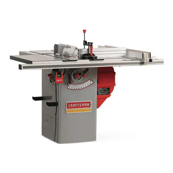
1.75 Horsepower (continuous duty)
2.4 Horsepower (maximum developed)
3450 R.P.M. (no load R.P.M.)
10-in. TABLE SAW
Model No.
152.221240
C
US
CAUTION:
FOR YOUR OWN SAFETY; Read
and follow all of the Safety and
Operating Instructions before
Operating this Table Saw.
Sears, Roebuck and Co., Hoffman Estates, IL 60179 U.S.A.
Part No. OR91552
Revised: REV. C
Customer Helpline
1-800-897-7709
Please have your Model No.
and Serial No. available.
Español pg. 48
Advertisement
Chapters
Table of Contents

Related Manuals for Craftsman 152.221240


Summary of Contents for Craftsman 152.221240
- Page 1 Owner’s Manual 1.75 Horsepower (continuous duty) 2.4 Horsepower (maximum developed) 3450 R.P.M. (no load R.P.M.) 10-in. TABLE SAW Model No. 152.221240 Customer Helpline CAUTION: 1-800-897-7709 FOR YOUR OWN SAFETY; Read and follow all of the Safety and Please have your Model No.
-
Page 2: Table Of Contents
TABLE OF CONTENTS SECTION PAGE Warranty ..................................2 Product Specifications ..............................2 Glossary of Terms................................3 Safety Instructions .................................4 Guidelines for Extension Cords ...........................5 Grounding Instructions ..............................6 Specific Safety Instructions for Table Saw........................7 Accessories and Attachments ............................9 Carton Contents ................................11 Know Your Table Saw ..............................15 Assembly Instructions..............................16 Operations and Adjustment to the Table Saw......................26 Maintenance..................................38... -
Page 3: Glossary Of Terms
GLOSSARY OF TERMS Anti-Kickback Fingers – A safety device attached to the Kerf – The material removed by the blade in the work- blade guard and splitter assembly designed to stop a piece during any cutting operation. workpiece from being thrown back during a cutting opera- tion. -
Page 4: Safety Instructions
SAFETY INSTRUCTIONS GENERAL SAFETY INSTRUCTIONS 9. ALWAYS WEAR EYE PROTECTION. Any power tool can throw debris into the eyes during opera- Operating a Table Saw can be dangerous if safety and tions, which could cause severe and permanent common sense are ignored. The operator must be eye damage. -
Page 5: Guidelines For Extension Cords
20. EACH AND EVERY TIME, CHECK FOR DAM- GUIDELINES FOR AGED PARTS PRIOR TO USING THE TOOL. EXTENSION CORDS Carefully check all guards to see that they operate properly, are not damaged, and perform their The smaller the gauge-number, the larger diameter of intended functions. -
Page 6: Grounding Instructions
GROUNDING INSTRUCTIONS WARNING USE ONLY A 3-WIRE EXTENSION CORD THAT HAS THIS TOOL MUST BE GROUNDED WHILE IN USE A 3-PRONG GROUNDING PLUG AND A 3-POLE TO PROTECT THE OPERATOR FROM ELECTRIC RECEPTACLE THAT ACCEPTS THE TOOL’S PLUG. SHOCK. REPLACE A DAMAGED OR WORN CORD IMMEDI- IN THE EVENT OF A MALFUNCTION OR BREAK- ATELY. -
Page 7: Specific Safety Instructions For Table Saw
It is also necessary to replace the 120 volt plug, sup- MAKE CERTAIN that masks or respirators are plied with the motor, with a UL/CSA Listed plug suitable MSHA/NIOSH approved. for 240 volts and rated current of the saw. Contact a The operation of any Table Saw can result in debris local qualified electrician for proper procedures to install being thrown into your eyes, which can result in severe... - Page 8 14. The Table Saw is designed for home use or light 27. NEVER perform layout, assembly or set-up work on commercial duty ONLY. the table/work area when the machine is running. 15. CONNECT Table Saw to a properly grounded outlet 28.
-
Page 9: Accessories And Attachments
ACCESSORIES AND ATTACHMENTS AVAILABLE ACCESSORIES Sears may recommend other accessories not listed in this manual. Visit your Sears Hardware Department or see the Sears See your nearest Sears Hardware Department or Sears Power and Hand Tool Catalog for the following acces- Power and Hand Tool Catalog for other accessories. - Page 10 CONSTRUCTING A PUSHSTICK WARNING When ripping work less than 4 inches wide, a pushstick should be used to complete the feed and could easily be made from scrap material by following the pattern shown in figure 2C. Fig. 2C The Pushstick should be made of 3/4 or 1/2 inch wood or a thickness less than the width of the workpiece to be cut.
-
Page 11: Carton Contents
CARTON CONTENTS Fig. 3-1 UNPACKING AND CHECKING CONTENTS WARNING The table saw is a heavy machine, two people are required to unpack and lift the table saw. This table saw will require some amount of assembly. This table saw is shipped in two separate cartons, one for the saw and one for the fence. - Page 12 FENCE Fig. 3-2 20. Rear rail 21. Front rail 22. Guide tube 23. Extension table assembly 24. T-Square ® fence assembly 25. Locking handle knob 26. Cursor (2) 27. Template Fig. 3-3 MITER GAUGE 40. Miter gauge 41. Cross cut fence 42.
- Page 13 Fig. 3-4 OUTFEED TABLE 50. Outfeed table assembly 51. Hinge assembly (2) 52. Clamp knob 53. Upper support assembly 54. Lower support 55. Support retainer Hardware packs are not identified or labeled. See hardware diagram to help in finding the correct part. See figure 3-5. •...
- Page 14 Fig. 3-5...
-
Page 15: Know Your Table Saw
KNOW YOUR TABLE SAW 1. Splitter assembly 9. Biesemeyer commercial T-square fence 17. Rip fence holder bracket 2. Anti-kickback fingers 10. Accessory Biesemeyer extension table 18. Blade height handwheel 3. Blade 11. Front rail with scale 19. Handwheel lock 4. Blade guard 12. -
Page 16: Assembly Instructions
ASSEMBLY INSTRUCTIONS TOOLS REQUIRED NOTE: If you will be permanently attaching your table saw to the floor, DO NOT assemble leveling feet and go The following tools are needed for assembly and align- on to the next step. ment. Note: Two blade wrenches and five hex wrenches are provided with your table saw. - Page 17 POLY-V BELT ASSEMBLY 1. CAUTION: The extension wings are heavy; two people are required to assemble both extension WARNING wings to the table saw. MAKE CERTAIN the table saw is disconnected from 2. Assemble one of the extension wings (A) to the left the power source.
- Page 18 1. Place one of the handwheels (A) onto the bevel BLADE GUARD AND SPLITTER ASSEMBLY shaft (B) located on the side of the cabinet. Align the groove (C) in the back of the handwheel with WARNING the pin (D). See figure 8-1. MAKE CERTAIN the table saw is disconnected from the power source.
- Page 19 Figure 10-3 Figure 10-5 4. Place the front attachment point (D) of the blade 7. Place a square (N) onto the saw table and against guard and splitter assembly (H) down into the the splitter assembly (O) behind the kickback fin- tool-less front attachment point (E).
- Page 20 Fig. 11-3 BIESEMEYER ® T-SQUARE ® COMMERCIAL RIP FENCE SYSTEM ASSEMBLY SAW TABLE FRONT AND REAR RAIL ASSEMBLY FRONT RAIL WARNING MAKE CERTAIN the table saw is disconnected from 4. Using the template (G), check and adjust front rail the power source. parallel to the table surface on both sides of the saw table.
- Page 21 IMPORTANT: Do not use template supplied to set the GUIDE TUBE AND SWITCH ASSEMBLY rear rail. Figure 11-7 8. Make sure the top edge of the front rail is below the top of the saw table and that the front rail is not blocking the ends of the miter gauge grooves.
- Page 22 KNOB AND CURSOR ASSEMBLY OUTFEED TABLE ASSEMBLY Figure 11-9 Figure 11-10 1. Thread knob (A) onto fence locking handle (B). Turn knob clockwise to screw it onto threads of fence locking handle. See figure 11-9. 2. Align left fence side (C) at a distance from the right side (D) of the right miter gauge groove and lock the fence.
- Page 23 4. Fold out lower and upper support arms straight, so CONNECTING SWITCH CORD that the pin (G) in the upper support goes into notch TO MOTOR CORD (H) of lower support and securely tighten clamp knob. WARNING MAKE CERTAIN the table saw is disconnected from 5.
- Page 24 MITER GAUGE ASSEMBLY Figure 13-2 WARNING MAKE CERTAIN the table saw is disconnected from the power source. Figure 13-1 4. Slide both of the square nuts with hex socket head screw and flat washer (F) into the lower T-slot (G) of the cross cut fence (H).
- Page 25 4. Open the motor cover (F) and remove the two holes at the four locations marked. Phillip head screws (G) from the CRAFTSMAN 10. Attach the table saw to the floor using appropriate nameplate (H). NOTE: These two Phillip head hardware (not included).
-
Page 26: Operations And Adjustment To The Table Saw
OPERATIONS AND ADJUSTMENTS CAUTION LOCKING ON/OFF SWITCH • A separate electrical circuit should be used for your 1. When the table saw is not in use, the “ON” button table saw. The table saw comes pre-wired for 120-volt should be locked so that it cannot be started. use. - Page 27 To lower the saw blade, loosen the handwheel lock 3. If the blade will not tilt to 90-degrees, turn (counter- knob (counterclockwise) and turn the handwheel clockwise) the set screw (C) in the left hand side of counterclockwise. When the saw blade is at its desired the saw table until the blade can be positioned to height, tighten the handwheel lock knob (clockwise) 90-degrees.
- Page 28 Figure 17-1 1. Raise the saw blade to its highest point. 2. Place a combination square (A) on the saw table with one edge (B) of the square against the left miter slot (C). See figure 17A-1. 3. Adjust the square so the rule (D) just touches the saw blade about 1 inch in from the outer diameter.
- Page 29 Fig. 17B-1 BIESEMEYER ® T-SQUARE ® COMMERCIAL RIP FENCE SYSTEM ASSEMBLY OPERATIONS AND ADJUSTMENTS WARNING MAKE CERTAIN the table saw is disconnected from the power source when making adjustments. Figure 18-1 1. To align the blade parallel to the miter slot, first loosen two hex head screws (A) under the left side of the table saw.
- Page 30 FENCE ALIGNMENT 3. Slightly tighten the two adjusting screws (I), using a 3/16” hex wrench (not supplied). NOTE: Screws should be tightened an equal amount. 1. The rip fence (A) must be adjusted so it is parallel See figure 18-2. to the miter gauge groove (G).
- Page 31 4. Once the insert is level, secure the insert with the 5. Replace junction box cover and close motor cover. retaining bolt removed in step 1. 6. Replace 120 volt plug with a UL/CSA Listed 240 5. The table insert is equipped with a finger hole (E) volt plug rated for current of the motor.
- Page 32 ALIGNING SPLITTER BRACKET 3. Retighten the two hex socket head cap screws after the splitter has been aligned. WARNING 4. If necessary, adjust the rear splitter bracket (F). Make certain that entire splitter is in line with the MAKE CERTAIN the table saw is disconnected from the power source.
- Page 33 3. To rotate to the next positive stop pull plunger out, CLAMP AND FENCE STOP OPERATION rotate miter gauge body then push plunger back in and continue rotating miter gauge body until it stops WARNING against next positive stop. MAKE CERTAIN the table saw is disconnected from the power source when making adjustments.
- Page 34 Crosscutting requires the use of the miter gauge (A) to position and guide the workpiece (B). See figure 24-1. WARNING The use of non-Craftsman attachments and acces- sories may result in risk of injury or damage to the table saw.
- Page 35 Ripping is the operation of making a cut with the grain of the workpiece; the rip fence (A) is used to position An accessory Craftsman Fence Guide can be pur- and guide the workpiece. Since the workpiece is chased to assist when making narrow cuts. See pushed along the fence, it must have a straight edge “ACCESSORIES AND ATTACHMENTS”...
- Page 36 DADO BLADE SET Dado blades and chippers have a set to their teeth. The teeth of the dado blades and chippers must be arranged so that the set of each tooth overlaps the next WARNING tooth. The set of the dado blade (C) and chipper (D) The blade guard and splitter assembly cannot be used overlap as shown in Figure 26-3.
- Page 37 Figure 26-5 WARNING • The blade guard and splitter assembly cannot be used when dadoing or molding and must be swung to the rear of the saw. Blade guard must be reassem- bled when finished. Figure 27-2 Figure 26-5, shows a typical dado operation using the miter gauge.
-
Page 38: Maintenance
Position the wood facing over the cutterhead with the CAUTION cutterhead below the surface of the table. Turn the saw • When molding end grain, the miter gauge must be on and raise the cutterhead slowly. The cutterhead will used. The feed should be slowed up at the end of cut its own groove in the wood facing. - Page 39 LUBRICATION WARNING The table saw has sealed lubricated bearings in the Only trained personnel should perform repairs to the motor housing that do not require any additional lubrica- table saw. Contact your nearest Sears Service Center tion from the operator. for authorized service.
-
Page 40: Troubleshooting Guide
TROUBLESHOOTING GUIDE TO PREVENT INJURY TO YOURSELF or damage to the table saw, turn the power switch to the “OFF” position and unplug the power cord from the electrical receptacle before making any adjustments. PROBLEM LIKELY CAUSE(S) SOLUTION Motor does not 1. -
Page 41: Part List
10-IN. TABLE SAW MODEL NO.152.221240 WARNING When servicing, use only CRAFTSMAN replacement parts. Use of any other parts may create a HAZARD or cause product damage. WARNING Any attempt to repair or replace electrical parts on this table saw may create a HAZARD unless a qualified service technician does repairs. - Page 42 10-IN. TABLE SAW MODEL NO.152.221240 Key No. PART No. Description Qty. Key No. PART No. Description Qty. OR90059 FLAT WASHER M6 OR91134 WRENCH HOOK OR91826 CHEESE HEAD SCREW M6 x 16mm OR91135 FENCE HOOK OR91804 HANDWHEEL ASSEMBLY, (NOT SHOWN) OR91832...
- Page 43 10-IN. TABLE SAW MODEL NO.152.221240...
- Page 44 10-IN. TABLE SAW MODEL NO.152.221240...
- Page 45 10-IN. TABLE SAW MODEL NO.152.221240...
- Page 46 10-IN. TABLE SAW MODEL NO.152.221240...
- Page 47 10-IN. TABLE SAW MODEL NO.152.221240...
-
Page 48: Espanol
1.75 caballos de fuerza (servicio continuo) 2.4 caballos de fuerza (máximo desarrollado) 3450 R.P.M. (R.P.M. sin carga) SIERRA DE MESA de 10 pulg. No. de Modelo 152.221240 Línea de Ayuda al Cliente PRECAUCIÓN: 1-800-897-7709 PARA SU SEGURIDAD PERSONAL: Sírvase tener listo su Lea y obedezca todas las Instrucciones No de Modelo y No. -
Page 49: Sección Garantía
TABLA DE MATERIAS SECCIÓN PÁGINA Garantía.......................................49 Especificaciones del producto................................49 Glosario de términos ...................................50 Instrucciones de seguridad .................................51 Directrices para las extensiones eléctricas ............................52 Instrucciones de conexión a tierra ..............................53 Instrucciones específicas de seguridad para las sierras de mesa .....................54 Accesorios y aditamentos ...................................56 Contenido de la caja....................................58 Conozca su sierra de mesa ................................62 Instrucciones de montaje ..................................63... -
Page 50: Glosario De Términos
GLOSARIO DE TÉRMINOS Alefriz – Muesca cuadrada en el borde del material. Fresa rotativa de ranurar – Corte no directo que produce una muesca cuadrada. Una fresa rotativa tiene, típicamente, un ancho de 1/8 a 13/16 pulg. Una fresa rotativa requiere un Contragolpe –... -
Page 51: Instrucciones De Seguridad
INSTRUCCIONES DE SEGURIDAD INSTRUCCIONES GENERALES DE UTILICE PROTECCIÓN OCULAR SIEMPRE. Cualquier herramienta mecánica puede arrojar escombros hacia los SEGURIDAD ojos durante el funcionamiento, pudiendo esto resultar en El funcionamiento de una Sierra de Mesa puede resultar heridas oculares graves y permanentes. Los anteojos de peligroso si se hace caso omiso de la seguridad y del sentido uso cotidiano NO son gafas de seguridad. -
Page 52: Directrices Para Las Extensiones Eléctricas
20. REVISE SI HAY PIEZAS DAÑADAS ANTES DE CADA DIRECTRICES PARA USO DE LA HERRAMIENTA. Revise todos los protec- LAS EXTENSIONES ELÉCTRICAS tors cuidadosamente para comprobar que funcionan correctamente y que no están dañados, y que realizan Mientras menor sea el número de calibre, mayor será el sus funciones diseñadas correctamente. -
Page 53: Instrucciones De Conexión A Tierra
INSTRUCCIONES DE CONEXIÓN A TIERRA ADVERTENCIA REPONGA CUALQUIER CORDÓN DAÑADO O GASTADO ESTA HERRAMIENTA DEBE ESTAR CONECTADA A TIER- RA DURANTE EL USO PARA PROTEGER AL OPERARIO INMEDIATAMENTE. CONTRA LOS CHOQUES ELÉCTRICOS. PARA LAS MÁQUINAS CONECTADAS A TIERRA Y CON EN EL CASO DE UN MALFUNCIONAMIENTO O AVERÍA, la CORDÓN DISEÑADAS PARA EL USO EN UN CIRCUITO conexión a tierra ofrece el trecho de menor resistencia para la... -
Page 54: Instrucciones Específicas De Seguridad Para Las Sierras De Mesa
También será necesario reemplazar el enchufe de 120 voltios ASEGÚRESE de que las máscaras o respiradores tienen suministrado con el motor por un enchufe clasificado por aprobación MSHA / NIOSH. UL/CSA como apropiado para los 240 voltios y la corriente clasificada de la sierra. - Page 55 14. La Sierra de Mesa está diseñada para el uso doméstico 27. JAMÁS realice labores de trazado, ensamblado o monta- o el uso comercial ligero SOLAMENTE. je sobre la mesa / zona de trabajo cuando la máquina se encuentre en funcionamiento. 15.
-
Page 56: Accesorios Y Aditamentos
ACCESORIOS Y ADITAMENTOS ACCESORIOS DISPONIBLES Sears podrá recomendar otros accesorios no listados en este manual. Visite su Departamento de Ferretería de Sears o consulte el Consulte su Departamento de Ferretería de Sears más cer- Catalogo de Herramientas Eléctricas y de Mano de Sears cano o el Catalogo de Herramientas Eléctricas y de Mano de para los siguientes accesorios: Sears para otros accesorios. - Page 57 CONSTRUYENDO UNA VARA DE EMPUJE ADVERTENCIA Durante el corte a lo largo de materiales con menos de 4 pulgadas de ancho. se debe hacer uso de una vara de empuje para completar la alimentación. Puede construirse fácilmente utilizando material descartado y siguiendo el patrón ilustrado en la Figura 2C.
-
Page 58: Contenido De La Caja
CONTENIDO DE LA CAJA DESEMPACANDO Y REVISANDO Figura 3-1 EL CONTENIDO ADVERTENCIA La sierra de mesa es una máquina pesada. Se requieren dos personas para desempaquetarla y levantar la sierra de mesa. Esta sierra de mesa requerirá cierta cantidad de ensamblado. Esta sierra de mesa se envía en dos cajas individuales, una para la sierra y otra para la guía. - Page 59 GUÍA Figura. 3-2 20. Riel posterior 21. Riel delantero 22. Tubo de guía 23. Ensamblado de extensión de mesa 24. Ensamblado de la guía de la escuadra en T 25. Perilla de la agarradera de cierre 26. Cursor (2) 27. Plantilla ESCUADRA DE INGLETES Figura 3-3 40.
- Page 60 MESA DE AVANCE DE SALIDA Figura. 3-4 50. Ensamblado de la mesa de avance de salida 51. Ensamblado de bisagras (2) 52. Perilla de abrazadera 53. Ensamblado de soporte superior 54. Soporte inferior 55. Retén del soporte Los estuches de ferretería no están identificados ni etiquetados. Consulte el diagrama de ferretería para ayudar a localizar la pieza correcta.
- Page 61 Fig. 3-5 TORNILLO DE CABEZA HEX M8 x 1.25 x 25 mm TORNILLO DE CABEZA HEX M8 x 1.25 x 30 mm TUERCA HEX M8 x 1.25 TUERCA HEX M6, TORNILLO DE CABEZA HEX 5/16-18 x 1-1/2 pulg. NYLOCK TUERCA HEX M5 TORNILLO DE CABEZA HEX M6 x 25 mm TUERCA HEX 5/16 pulg.-18 TORNILLO DE CABEZA HEX M6 x 35 mm...
-
Page 62: Conozca Su Sierra De Mesa
CONOZCA SU SIERRA DE MESA 1. Ensamblado del hendidor 13. Cubierta del motor 2. Dedos anticontragolpe 14. Escuadra de biselado 3. Hoja 15. Gabinete completo 4. Protector de hoja 16. Pie nivelador 5. Pieza inserta de alineamiento de corte 17. Soporte de sujeción de la guía de corte a lo largo 6. -
Page 63: Instrucciones De Montaje
INSTRUCCIONES DE MONTAJE HERRAMIENTAS REQUERIDAS AVISO: Si va a afianzar su sierra de mesa al suelo perma- nentemente, NO ENSAMBLE las patas niveladoras y prosiga Se requieren las siguientes herramientas para el montaje y el al siguiente paso. alineamiento. Aviso: Se suministran dos llaves de hoja y cinco llaves hexagonales con su sierra de mesa. - Page 64 MONTAJE DE LA CORREA POLY-V PRECAUCIÓN: Las alas de extensión son pesadas. Se requieren dos personas para ensamblar ambas alas de extensión a la sierra de mesa. ADVERTENCIA Monte una de las alas de extensión (A) al lado izquierdo ASEGÚRESE de que la sierra de mesa esté desconectada de la sierra de mesa.
- Page 65 Coloque uno de los volantes de mano (A) sobre el eje MONTAJE DEL PROTECTOR DE biselado (B) localizado en el lado del gabinete. La ranura HOJAS Y HENDIDOR (C) en el dorso del volante debe alinearse con el pasador (D). Ver la figura 8-1. ADVERTENCIA Figura 8-2 ASEGÚRESE de que la sierra de mesa esté...
- Page 66 Figura 10-3 Figura 10-5 Coloque el punto de conexión delantero (D) del ensam- Coloque una escuadra (N) sobre la mesa de la sierra y blado de protector de hoja y de hendidor (H) sobre el contra el ensamblado del hendidor (O) detrás de los punto de conexión delantero que carece de herramientas dedos anticontragolpe (P).
- Page 67 Figura 11-3 ENSAMBLADO DEL SISTEMA COMERCIAL DE GUÍA DE CORTE A LO LARGO EN MESA DE LA ESCUADRA “T” DE BIESEMEYER SIERRA RIEL MONTAJE DE LOS RIELES DELANTERO Y DELANTERO TRASERO ADVERTENCIA Usando la plantilla (G), revise y ajuste el riel delantero ASEGÚRESE de que la mesa esté...
- Page 68 IMPORTANTE: No utilice la plantilla suministrada para fijar el ENSAMBLADO DEL TUBO DE GUÍA riel trasero. Y CONMUTADOR Asegúrese de que el borde superior del riel delantero Figura 11-7 esté por debajo de la parte superior de la mesa de la sierra y que el riel delantero no esté...
- Page 69 ENSAMBLADO DE LA PERILLA Y CURSOR ENSAMBLADO DE LA MESA DE AVANCE DE SALIDA Figura 11-9 Figura 11-10 Enrosque la perilla (A) sobre la agarradera de cierre de la guía (B). Gire la perilla en sentido horario para atornillarla sobre las roscas de la agarradera de cierre de la guía.
- Page 70 Desdoble los brazos de soporte inferior y superior hasta CONECTANDO EL CORDÓN DEL dejarlos rectos, de manera que el pasador (G) en el INTERRUPTOR AL CORDÓN DEL MOTOR soporte superior pueda insertarse en la muesca (H) del soporte inferior, y afiance la perilla de abrazadera ADVERTENCIA seguramente.
- Page 71 MONTAJE DE LA ESCUADRA DE Figura 13-2 INGLETES ADVERTENCIA ASEGÚRESE de que la sierra de mesa esté desconectada de la fuente de energía. Figura 13-1 Coloque la sección roscada de los tornillos de cabeza hueca hexagonal en las ranuras (I) del cuerpo de la escuadra de ingletes.
- Page 72 EMPERNANDO LA SIERRA DE MESA FIgura 13A-3 AL PISO ADVERTENCIA ASEGÚRESE de que la sierra de mesa esté desconectada de la fuente de energía. Si lo desea, la sierra de mesa puede montarse al piso de forma permanente. Para conectarla al piso, consulte las siguientes instrucciones: FIgura 13A-1 Quite los nueve tornillos de cabeza Phillips (I) del lado...
-
Page 73: Operaciones Y Ajustes
OPERACIONES Y AJUSTES PRECAUCIÓN ENCLAVANDO EL INTERRUPTOR DE ENCENDIDO/APAGADO • Debe hacerse uso de un circuito eléctrico individual para su sierra de mesa. La sierra de mesa viene cableada Cuando la sierra de mesa no se encuentre en uso, el de antemano para el funcionamiento a 120 voltios. - Page 74 Para bajar la hoja de la sierra, afloje la perilla de cierre del Si la hoja no se inclina a 90 grados, gire el tornillo de volante de mano (en sentido antihorario) y gire el volante de fijación (C) (en sentido antihorario) al lado izquierdo de la mano en sentido antihorario.
- Page 75 Figura 17-1 Eleve la hoja de la sierra a su punto más alto. Coloque una escuadra de combinaciones (A) sobre la mesa de la sierra con uno de los bordes (B) de la escuadra contra la ranura de ingletes izquierda (C). Ver figura 17A-1.
- Page 76 Figura 17B-1 ENSAMBLADO DEL SISTEMA COMERCIAL DE GUÍA DE CORTE A LO LARGO CON ESCUADRA “T” DE BIESEMEYER OPERACIONES Y AJUSTES ADVERTENCIA ASEGÚRESE de que la sierra de mesa esté desconectada de la fuente de energía durante la realización de los ajustes. Figura 18-1 Para alinear el paralelo de la hoja con la ranura de ingletes, afloje primero las dos tuercas de cabeza hexa-...
- Page 77 ALINEAMIENTO DE LA GUÍA Apriete ligeramente los dos tornillos de ajuste (I) usando una llave hexagonal de 3/16 pulg. (no suministrada). La guía de corte a lo largo (A) debe ajustarse de tal AVISO: Los tornillos deben afianzarse en cantidades manera que quede paralela con la ranura de la escuadra iguales.
- Page 78 Una vez que la pieza de inserción de mesa esté nive- Reponga la cubierta de la caja de empalmes y cierre la lada, afiance la pieza con el perno de retén que fue cubierta del motor. removido en el paso 1. Reponga el enchufe de 120 voltios por uno de 240 La pieza de inserción de mesa viene equipada con un voltios clasificado por UL/CSA para la corriente del motor.
- Page 79 ALINEANDO EL SOPORTE DEL HENDIDOR Vuelva a apretar los dos tornillos de cabeza hueca hexagonal después de haber alineado el hendidor. ADVERTENCIA Si resulta necesario, ajuste el soporte del hendidor posterior (F) asegurándose de que el hendidor completo ASEGÚRESE de que la sierra de mesa esté desconectada esté...
- Page 80 Para girar al siguiente tope positivo, extraiga el émbolo, OPERACIÓN DE LA ABRAZADERA Y DEL gire el cuerpo de la escuadra de ingletes, luego vuelva a TOPE DE LA GUÍA empujar el émbolo hacia adentro y siga girando el cuerpo de la escuadra de ingletes hasta que se detenga en el ADVERTENCIA siguiente tope positivo.
-
Page 81: Corte Transversal
(A) para posicionar y guiar el material (B). Ver la figura 24-1. ADVERTENCIA El uso de aditamentos y accesorios que no sean de Craftsman podrá resultar en el riesgo de lesiones al usuario o daño a la sierra de mesa. Figura 24-1 GUÍA AUXILIAR... - Page 82 SIEMPRE mantenga las manos y los dedos alejados de la hoja de la sierra. Figura 25-1 Puede comprarse una Guía Craftsman de accesorio como ayuda cuando vaya a efectuar cortes angostos. Vea la sección “ACCESORIOS Y ADITAMENTOS” en este manual.
- Page 83 CONJUNTO DE FRESAS ROTATIVAS Los dientes de las fresas rotativas y las astilladoras tienen gradación. Los dientes de las fresas rotativas y las astillado- DE RANURAR ras deben estar dispuestas de tal forma que la gradación de cada diente esté solapada con la del próximo diente. Las ADVERTENCIA gradaciones de la fresa rotativa (C) y la astilladora (D) se solapan como se ilustra en la Figura 26-3.
- Page 84 Figura 26-5 ADVERTENCIA El protector de hoja y el ensamblado del hendidor no pueden utilizarse durante el fresado o el moldurado y deben bascu- larse hacia la parte trasera de la sierra. El protector de hoja debe reensamblarse cuando haya terminado. Figura 27-2 La Figura 26-5 muestra una operación típica de fresado haciendo uso de la escuadra de ingletes.
-
Page 85: Mantenimiento
Posicione el refrentado de madera sobre el cabezal de corte PRECAUCIÓN con el cabezal de corte por debajo de la superficie de la mesa. Encienda la sierra y eleve el cabezal de corte lenta- Durante el moldurado a contrahilo debe hacerse uso de la mente. - Page 86 LUBRICACIÓN ADVERTENCIA La sierra de mesa tiene cojinetes lubricados sellados en la Sólo personal competente debe realizar reparaciones a la carcasa del motor que no requieren lubricación adicional por sierra de mesa. Comuníquese con su Centro de Servicio parte del operario. Sears más cercano para obtener servicio autorizado.
-
Page 87: Guía De Localización De Averías
GUÍA DE LOCALIZACIÓN DE AVERÍAS Para evitar herirse a sí mismo o dañar la sierra de mesa, conmute el interruptor de energía a “APAGADO” y desenchufe el cordón de potencia del tomacorrientes antes de realizar cualquier ajuste. PROBLEMA CAUSAS POSIBLES SOLUCION Motor no arranca: 1. -
Page 88: Service Information
Get it fixed, at your home or ours! Your Home For repair – in your home – of all major brand appliances, lawn and garden equipment, or heating and cooling systems, no matter who made it, no matter who sold it! For the replacement parts, accessories and owner’s manuals that you need to do-it-yourself.