Advertisement
Table of Contents
- 1 Safety Rules
- 2 Additional Safety Rules for Drill Presses
- 3 Unpacking and Cleaning
- 4 Permanent Mounting
- 5 Grounding Instructions
- 6 Volt Operation
- 7 Extension Cords
- 8 Locking Switch in the "Off" Position
- 9 Spindle Speeds
- 10 Drilling Holes to Depth
- 11 Installing and Removing Drill Bits
- 12 Drilling Metal
- Download this manual
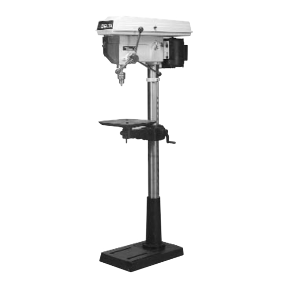
16½" Floor Model Drill Press
(Model 17-900)
PART NO. 900603 (011)
Copyright © 2001 Delta Machinery
To learn more about DELTA MACHINERY
ESPAÑOL: PÁGINA 17
visit our website at: www.deltamachinery.com.
For Parts, Service, Warranty or other Assistance,
1-800-223-7278 (
1-800-463-3582).
please call
In Canada call
Advertisement
Table of Contents

Related Manuals for Delta 17-900


Summary of Contents for Delta 17-900
- Page 1 16½" Floor Model Drill Press (Model 17-900) PART NO. 900603 (011) Copyright © 2001 Delta Machinery To learn more about DELTA MACHINERY ESPAÑOL: PÁGINA 17 visit our website at: www.deltamachinery.com. For Parts, Service, Warranty or other Assistance, 1-800-223-7278 ( 1-800-463-3582).
-
Page 2: Safety Rules
If you have any questions relative to a particular application, DO NOT use the machine until you have first contacted Delta to determine if it can or should be performed on the product. -
Page 3: Additional Safety Rules For Drill Presses
4. NEVER turn the tool “ON” before clearing the table of all objects (tools, scrap pieces, etc.). 5. NEVER start the drill press with the drill bit or cutting tool in contact with the workpiece. 6. USE ONLY drill bits, cutters, sanding drums and other accessories with 5/8"... -
Page 4: Unpacking And Cleaning
Carefully unpack the drill press and all loose items from the shipping container(s). Remove the protective coating from the machined surfaces of the drill press. This coating may be removed with a soft cloth moistened with kerosene. Do not use acetone, gasoline or lacquer thinner for this purpose. Figs. 2 and 3 illustrate the components of the drill press. - Page 5 4. Carefully position drill press head (J) Fig. 6, onto column (A) as far as it will go. Align drill press head (J) Fig. 6, and table (G) Fig. 5, with the base of the drill...
- Page 6 10. The drill press is shipped from the factory with the belts assembled on the pulleys; however, the belts must be properly tensioned before use. Refer to section “CHANGING SPINDLE SPEEDS AND ADJUSTING BELT...
-
Page 7: Permanent Mounting
SUPPORTING SURFACE If your drill press is to be used in one permanent location, the drill press base must be secured to the supporting surface with fasteners through the two mounting holes, (A) Fig. 10, in the drill press base. -
Page 8: Grounding Instructions
YOU ARE NOT SURE, HAVE A QUALIFIED ELECTRICIAN CHECK THE RECEPTACLE. 120 VOLT OPERATION As received, your drill press is ready-to-run for 120 volt operation. This drill press, when wired for 120 volts, is intended for use on a circuit that has an outlet and a plug that looks like the one shown in Fig. -
Page 9: Extension Cords
3-prong grounding type plug and a 3-hole receptacle which will accept the tool’s plug. When using an extension cord, be sure to use one heavy enough to carry the current of the drill press. An undersized cord will cause a drop in line voltage resulting in loss of power and overheating. -
Page 10: Locking Switch In The "Off" Position
STARTING AND STOPPING DRILL PRESS The switch (A) Fig. 17, is located on the front of the drill press head. To turn the drill press “ON” move the switch to the up position. To turn the drill press “OFF” move the switch to the down position. -
Page 11: Spindle Speeds
Twelve spindle speeds are available on the drill press. Fig. 23, illustrates the speeds and which steps of the pulleys the belts must be positioned to obtain the 12 speeds. -
Page 12: Drilling Holes To Depth
CHANGING SPINDLE SPEEDS AND ADJUSTING BELT TENSION 1. DISCONNECT THE DRILL PRESS FROM THE POWER SOURCE. 2. Raise the belt and pulley guard (A) Fig. 24. 3. Release tension on the belt by loosening lock knob (B) Fig. 24, and the tension knob located on the other side of the head casting and moving tension lever (C) forward. - Page 13 IMPORTANT: When the workpiece is long enough, it should always be positioned on the table with one end against the column, as shown in Fig. 30. This prevents the workpiece from rotating with the drill bit or cutting tool, causing damage to the workpiece or personal injury to the operator.
-
Page 14: Installing And Removing Drill Bits
Use clamps to hold the work when drilling in metal. The work should never be held in the bare hand; the lips of the drill may seize the work at any time, especially when breaking through the stock. If the workpiece is whirled out of the operator’s hand, he may be injured. - Page 15 NOTES...
- Page 16 Delta recommended accessories should be used with this product. All Delta Machines and accessories are manufactured to high quality standards and are serviced by a network of Porter-Cable/Delta Factory Service Centers and Delta Authorized Service Stations. To obtain additional information regarding your Delta quality product or to obtain parts, service, warranty assistance, or the location of the nearest service outlet, please call 1-800-223-7278 (In Canada call 1-800-463-3582).