Advertisement
Table of Contents
- 1 Safety Rules
- 2 Additional Safety Rules for Drill Presses
- 3 Grounding Instructions
- 4 Extension Cords
- 5 Operating Instructions
- 6 Unpacking and Cleaning
- 7 Operating Controls and Adjustments
- 8 Belt Tension
- 9 Operation
- 10 Correct Drilling Speeds
- 11 Drilling Metal
- Download this manual
See also:
Instruction Manual
Advertisement
Table of Contents

Related Manuals for Delta 70-200


Summary of Contents for Delta 70-200
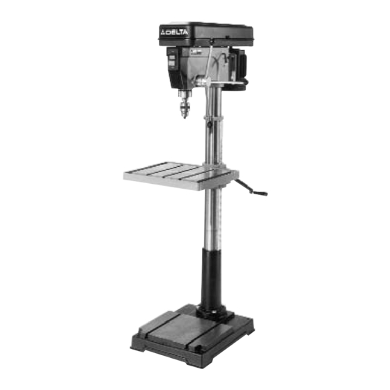
- Page 1 20" Drill Press (Model 70-200) PART NO. 900615 (0012) Copyright © 2000 Delta Machinery To learn more about DELTA MACHINERY ESPAÑOL: PÁGINA 17 visit our website at: www.deltamachinery.com. For Parts, Service, Warranty or other Assistance, 1-800-223-7278 ( 1-800-463-3582). please call...
-
Page 2: Safety Rules
If you have any questions relative to a particular applica- tion, DO NOT use the machine until you have first contacted Delta to determine if it can or should be performed on the product. -
Page 3: Additional Safety Rules For Drill Presses
12. USE recommended speed for drill, accessory or work-piece material. 13. WARNING: The use of accessories or attachments not recommended by Delta may result in risk of injury. 14. MAKE CERTAIN all lock handles are tightened before starting the machine. -
Page 4: Grounding Instructions
Your drill press is designed to use a 1720 RPM motor. It is wired at the factory for 110-120 Volts, 60 Hz alternating cur- rent. Never use a motor that runs faster than 1720 RPM. Your drill press may be converted for 220-240 volt operation. -
Page 5: Extension Cords
OPERATING INSTRUCTIONS FOREWORD The Delta Model 70-200 Drill Press provides production capacity drilling and includes; 1 hp single phase 115/230 volt induction motor, pulleys, belts, 0 - 5/8 capacity chuck, 45 degree tilt table L/R, rack and pinion table raising mechanism and #3 Morse Taper spindle adaptor. -
Page 6: Unpacking And Cleaning
Carefully unpack the drill press and all loose items from the carton. Remove the protective coating from the machined surfaces of the drill press and all loose items. This coating may be removed with a soft cloth moist- ened with kerosene. DO NOT USE ACETONE, GASOLINE, OR LACQUER THINNER FOR THIS PURPOSE. - Page 7 3. Assemble worm gear (J) Fig. 4, to the inside of hole (K) in table bracket (H). 4. Thread table lock lever (M) Fig. 4, into hole in table bracket, as shown. 5. Place raising rack (E) Fig. 5, in position inside table bracket (H) making sure gear on inside of table bracket is engaged with teeth of raising rack.
- Page 8 8. Reassemble collar (D) Fig. 7, which was removed in STEP 1, to column. IMPORTANT: Bottom of collar (D) MUST NOT be pushed all the way down onto top of rais- ing rack (E). MAKE SURE top of raising rack (E) is under bottom of collar (D) and that there is enough clearance to allow rack (E) to rotate around the column.
- Page 9 15. Open the chuck jaws as wide as possible by turning the chuck sleeve (X) Fig. 15. 16. Place a block of wood (Y) Fig. 15, on the drill press table and lower the spindle until the chuck contacts the piece of wood.
- Page 10 FASTENING DRILL PRESS BASE TO A SUPPORTING SURFACE PERMANENT MOUNTING If your drill press is to be used in one permanent loca- tion, the drill press base must be secured to the sup- porting surface with fasteners through the four mounting holes, (A) Fig.
-
Page 11: Operating Controls And Adjustments
OPERATING CONTROLS AND ADJUSTMENTS START/STOP SWITCH The switch is located on the front of the drill press head. To start the machine, press the start button (A) Fig. 23, and to stop the machine, press the stop button (B). LOCKING SWITCH IN THE “OFF”... - Page 12 To adjust the return spring, proceed as follows: 1. DISCONNECT THE DRILL PRESS FROM THE POWER SOURCE. 2. Loosen the two nuts (B) Fig. 28, approximately one- quarter inch.
-
Page 13: Operation
Factors which determine the best speed to use in any drill press operations are: kind of material being worked, size of hole, type of drill or other cutter, and quality of cut desired. The smaller the drill, the greater the required RPM. In soft materials, the speed should be higher than for hard metals. -
Page 14: Drilling Metal
Do not use hand bits which have a screw tip; at drill press speeds they turn into the wood so rapidly as to lift the work off the table and whirl it. - Page 15 NOTES...
- Page 16 Delta Building Trades and Home Shop Machinery Delta will repair or replace, at its expense and at its option, any Delta machine, machine part, or machine accessory which in normal use has proven to be defective in workmanship or material, provided that the customer returns the product pre- paid to a Delta factory service center or authorized service station with proof of purchase of the product within two years and provides Delta with reasonable opportunity to verify the alleged defect by inspection.
- Page 17 Parts and accessories for Porter-Cable Delta products should be obtained by contacting any Porter-Cable Delta Distributor, Authorized Service Center, or Porter-Cable Delta Factory Service Center. If you do not have access to any of these, call 888-848-5175 and you will be directed to the nearest Porter-Cable Delta Factory Service Center.