Table of Contents
Advertisement
Advertisement
Table of Contents

Related Manuals for Delta 11-990C


Summary of Contents for Delta 11-990C
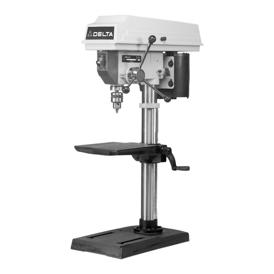
- Page 1 Français au verso 12" Bench Drill Press (Model 11-990C) PART NO. 1234956 (011) Copyright © 2001 Delta Machinery To learn more about DELTA MACHINERY visit our website at: www.deltamachinery.com. For Parts, Service, Warranty or other Assistance, 1-800-GO-DELTA (463-3582). please call...
-
Page 2: Safety Rules
If you have any questions relative to a particular application, DO NOT use the machine until you have first contacted Delta to determine if it can or should be performed on the product. -
Page 3: Additional Safety Rules For Drill Presses
4. NEVER turn the tool “ON” before clearing the table of all objects (tools, scrap pieces, etc.). 5. NEVER start the tool with the drill bit or cutting tool in contact with the workpiece. 6. USE ONLY drill bits, cutters, sanding drums and other accessories with 1/2"... -
Page 4: Unpacking And Cleaning
Your drill press is shipped complete in one container. Carefully unpack the drill press and all loose items from the container. Figure 2 illustrates the drill press and all loose items supplied with the machine. After assembly remove the protective coating from the table surface. This coating may be removed with a soft cloth moistened with kerosene (do not use acetone, gasoline or lacquer thinner for this purpose). - Page 5 1. Assemble the column (A) Fig. 3, to the base (B) using the four screws (C), three of which are shown. Loosen set screw (D) and remove ring (E) and raising rack (F). 2. Make certain worm gear (G) Figs. 4 and 5, is in place in table bracket (H) as shown.
- Page 6 4. Slide raising rack (F) Fig. 7, table and table bracket onto drill press column, as shown. Make sure bottom of raising rack (F) Fig. 8, is engaged with flange (J) on drill press base. 5. Re-assemble ring (E) Fig. 9, which was removed in STEP 1.
- Page 7 8. Thread clamp handle (M) Fig. 12, into hole in rear of table bracket, as shown. 9. Place the drill press head (N) Fig. 13, onto the column as far as it will go. Align head to table and base and tighten the two head locking screws (O) with wrench supplied.
-
Page 8: Fastening Drill Press Tosupporting Surface
NEVER drive the chuck onto the spindle with a metal hammer. FASTENING DRILL PRESS TO If during operation there is any tendency for the drill press to tip over, slide or walk on the supporting surface, the drill press base must be secured to the supporting surface with fasteners through the two holes (A) Fig. -
Page 9: Grounding Instructions
CONNECTING TOOL TO POWER SOURCE A separate electrical circuit should be used for your tools. This circuit should not be less than #12 wire and should be protected with a 20 Amp time lag fuse. If an extension cord is used, use only 3-wire extension cords which have 3-prong grounding type plugs and 3-pole receptacles which accept the tool’s plug. -
Page 10: Extension Cords
STARTING AND STOPPING DRILL PRESS The switch (A) Fig. 21, is located on the front of the drill press head. To turn the drill press “ON” move the switch to the up position. To turn the drill press “OFF” move the switch to the down position. - Page 11 1. The table can be raised or lowered on the drill press column by loosening the table clamp handle (A) Fig. 23, and turning the table raising and lowering handle (B) Fig. 24. After the table is at the desired height, tighten handle (A) Fig.
-
Page 12: Spindle Speeds
(B) Fig. 29, and pivoting the motor toward the front of the drill press, as shown. 4. While holding the motor toward the front of the drill press head, position the belt (C) on the desired steps of the motor and spindle pulleys, as shown in Fig. 29. A belt positioning chart (D) is provided on the inside top cover of the drill press for your convenience. -
Page 13: Operation
WARNING: The use of accessories and attach- ments not recommended by Delta may result in risk of injury. IMPORTANT: When the workpiece is long enough it should always be positioned on the table with one end against the column, as shown in Fig. -
Page 14: Drilling Metal
Do not use hand bits which have a screw tip; at drill press speeds they turn into the wood so rapidly as to lift the work off the table and whirl it. - Page 15 NOTES...
-
Page 16: Parts, Service Or Warranty Assistance
Delta Building Trades and Home Shop Machinery Delta will repair or replace, at its expense and at its option, any Delta machine, machine part, or machine accessory which in normal use has proven to be defective in workmanship or material, provided that the customer returns the product prepaid to a Delta factory service center or authorized service station with proof of purchase of the product within two years and provides Delta with reasonable opportunity to verify the alleged defect by inspection.