dbx DriveRack 480 User Manual
Complete equalization & loudspeaker management system
Hide thumbs
Also See for DriveRack 480:
- User manual (141 pages) ,
- Specifications (2 pages) ,
- Monitor application manual (32 pages)

Related Manuals for dbx DriveRack 480


Summary of Contents for dbx DriveRack 480
- Page 1 ® Complete Equalization & Loudspeaker Management System 480R ® User Manual...
-
Page 2: Important Safety Instructions
IMPORTANT SAFETY INSTRUCTIONS C A U T I O N R I S K O F E L E C T R I C S H O C K D O N O T O P E N A T T E N T I O N : R I S Q U E D E C H O C E L E C T R I Q U E - N E P A S O U V R I R W A R N I N G : T O R E D U C E T H E R I S K O F F I R E O R E L E C T R I C... -
Page 3: Declaration Of Conformity
European Contact: Your Local dbx Sales and Service Office or DECLARATION OF CONFORMITY dbx Professional Products 8760 S. Sandy Parkway Sandy, Utah 84070, USA declares that the product: Product name: dbx DriveRack™ 480,481 and 482 Product option: None Safety: EN 60065 (1993) IEC 60065 (1998) CAN/CSA E60065-99... -
Page 4: Table Of Contents
1.1 Defining the DriveRack™ System ...ii 1.2 Service Contact Info ...iv 1.3 Warranty...iv Section 1 - Getting Started 1.1 Rear Panel Connections (480) ...2 1.2 Front Panel (480) ...3 1.3 Rear Panel Connections (481) ...4 1.4 Front Panel (481) ...5 1.5 Rear Panel Connections (482) ...6... - Page 5 ™ DriveRack Table of Contents Section 8 - 480 Remote Controller 8.1 Rear Panel Connections ...74 8.2 Front Panel Connections...75 8.3 Rear Panel Connections (480P) ...76 8.4 Front Panel (480P) ...77 8.5 Using the RTA...78 8.6 Hot Key Assignments...79 8.7 Controlling Slave Units ...79 Section 9 - Application Guide 9.1 Four Way FOH ...82...
- Page 6 ™ DriveRack INTRODUCTION INTRO CUSTOMER SERVICE INFO Defining the DriveRack WARRANTY INFO ®...
-
Page 7: Defining The Driverack™ System
1.1 Defining the DriveRack™ System The dbx DriveRack™ is the most effective way to manage all aspects of post mix processing and signal routing. The following are just some of the features of the 480, 481, 482 and 480R. 480 DriveRack™ features: •... - Page 8 • RS-232 PC Interface for computer display and configuration 480R DriveRack™ features: • Dedicated remote interface to control all 480, 481 and 482 DriveRack™ units • 31 Motorized faders for equalization control • 32 assignable hot-keys with up to 64 different assignment capabilities •...
-
Page 9: Service Contact Info
In addition, the 481 utilizes euroblock connectors as opposed to the XLR connectors found in the 480 and 482 DriveRack. The 480, 481 and 482 DriveRacks™ include features such as: pre-crossover EQ, dual RTAs, notch filters, speaker delays, multiple crossovers and compression/limiting, as well as numerous other features. - Page 10 ™ DriveRack 2. dbx warrants this product, when bought and used solely within the U.S., to be free from defects in materials and workmanship under normal use and service. 3. dbx liability under this warranty is limited to repairing or, at our discretion, replacing defective materials that show evidence of defect, provided the product is returned to dbx WITH RETURN AUTHORIZATION from the factory, where all parts and labor will be covered up to a period of two years.
- Page 11 Section 1 ™ DriveRack Getting Started ®...
-
Page 12: Section 1 - Getting Started
1.1 Rear Panel Connections (480) IEC Power Cord Receptacle The 480 comes with an International power supply that will accept voltages ranging from 100V- 240V at frequencies from 50Hz-60Hz. An IEC cord is included. MIDI In, Out and Thru Connectors These connectors provide MIDI functionality to the 480 DriveRack™. -
Page 13: Front Panel (480)
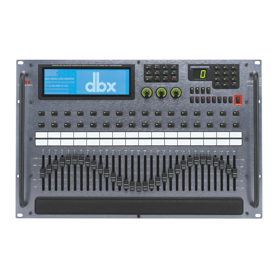
1.2 Front Panel (480) LCD Display The large LCD display of the 480 DriveRack™ provides the user with all of the vital processing information of the DriveRack™ including: signal routing, configuration modes, effect block edit- ing and RTA displays. The top left corner of the display indicates network device ID numbers. -
Page 14: Rear Panel Connections (481)
Input Meters The 480 DriveRack™ provides the user with four independent 12 seg- ment Lightpipe™ input meters that range from -30 to +22 dBu. Note: These meters are calibrated for the +22dBu setting of the gain jumpers. -
Page 15: Front Panel (481)
These LEDS indicate when network is properly terminated. The Green LED indicates that the network has been correctly terminated. Remote Controller In Connection This DB-9 type input connection is used to send and receive information from the 480 Remote DriveRack™ Unit. Outputs 1-8 (Euroblock Connectors) The output section of the 481 DriveRack™... -
Page 16: Rear Panel Connections (482)
™ DriveRack Section 1 Getting Started This LED (when lit), indicates that the 481 is connected to the control bus. When it is flashing, the 481 is sending/receiving network information. Remote LED This LED (when lit), indicates that the 481 is connected to the 480R. When it is flashing, the 481 is sending/receiving information from the 480R. -
Page 17: Front Panel (482)
These LEDS indicate when network is properly terminated. The Green LED indicates that the net- work has been correctly terminated. Remote Controller In Connection This DB-9 type input connection is used to send and receive information from the 480 Remote DriveRack™ Unit. PC Connection This DB-9 type connection is used to send and receive information to and from the GUI interface. - Page 18 ™ DriveRack Section 1 Getting Started PC Connection This DB-9 type connection is used to send and receive information to and from the GUI interface. Program Up and Down These program up and down buttons are used to scroll through the pro- gram menu of the 482.
-
Page 19: Section 2 - Editing Functions
Section 2 ™ DriveRack Editing Functions EDITING FUNCTIONS ®... -
Page 20: Basic Navigation Modes
Simply stated, the 480 DriveRack™ operating system was Functions designed with user’s best interest in mind. Editing the 480 DriveRack™ can be done by utiliz- ing key functions and tools. This section will provide you with detailed information on all of the tools used to optimize the editing performance of your DriveRack™. - Page 21 ™ DriveRack 2.2 FX Button Array Overview (cont.) PREVIOUS PAGE - Moves to the previous page in the currently selected effect menu. NEXT PAGE - Moves to the next page in the currently selected effect menu. EQ - Selects the EQ effect menu. Successive presses will rotate through the various EQ modules.
-
Page 22: Parameter Knob Encoders Coarse/Fine
Editing Functions 2.3 Parameter Knob Encoders Coarse/Fine Operation The parameter knob encoders of the 480 and 480R DriveRack™ Remote provide the user with the option of coarse or fine performance modes. This means that the parameter knobs can be set to either move or change values at a rapid (coarse) or slower (fine) rate. This option can be selected in any mode by simply pressing the selected parameter knob. -
Page 23: Navigating The Eq Sections
™ DriveRack Section 2 Editing Functions 2.5 Navigating the EQ Sections ® DriveRack™ User Manual... - Page 24 ™ DriveRack Section 2 Editing Functions 2.6 Navigating the XOVER ® DriveRack™ User Manual...
-
Page 25: Navigating The Rta Section
™ DriveRack Section 2 Editing Functions 2.7 Navigating the RTA ® DriveRack™ User Manual... -
Page 26: Navigating The Delay Section
™ DriveRack Section 2 Editing Functions 2.8 Navigating the Delay ® DriveRack™ User Manual... -
Page 27: Navigating The Dynamics Section
™ DriveRack Section 2 Editing Functions 2.9 Navigating the Dynamics Section ® DriveRack™ User Manual... -
Page 28: Navigating The Other Section
™ DriveRack Section 2 Editing Functions 2.10 Navigating the Other Section ® DriveRack™ User Manual... -
Page 29: Navigating The Utility Section
™ DriveRack Section 2 Editing Functions 2.11 Navigating the Utility Section ® DriveRack™ User Manual... - Page 30 Section 3 ™ DriveRack SOFTWARE CONFIGURATION FUNCTIONS ®...
-
Page 31: Section 3 - Configuring The Driverack
Section 3 Configuring the DriveRack™ The Configuring section of the 480, 481 and 482 DriveRack™ units will be your key to suc- cessful navigation of the configuration functions of the DriveRack™. The following information provides, descriptions about program functions and in depth configuration options of the 480, 481 and 482 DriveRack™... - Page 32 ™ DriveRack Section 3 Configuring the DriveRack™ Navigation Modes Once you have selected a program that utilizes a configuration that accommodates your appli- cation, the DriveRack™ offers different modes of navigation to access and edit effect types with- in the selected configuration. To instantly access an effect module, simply press the corresponding button in the button array for the desired module.
-
Page 33: Editing Factory Programs
Section 3 Configuring the DriveRack™ 3.3 Editing Factory Programs Once you have reached the module that you wish to edit, simply use the PREV PG and NEXT PG buttons to move through the pages within the module. The PARA- METER knobs are used to edit parameter values. The following illustration shows an exam- ple of the Compressor/Limiter module in edit mode: 3.4 Saving Factory Programs Changes Once you are satisfied with the changes that have been made to a factory or user program, the... - Page 34 ™ DriveRack • Once you are satisfied with the selected name press, the STORE button again and the screen will appear something like this: • If you wish to replace an existing User program, press the PARAMETER 1 knob and the display will appear as follows: •...
-
Page 35: Creating A User Configuration
Section 3 Configuring the DriveRack™ 3.5 Creating a User Configuration User Configuration creation is an ideal feature available in the DriveRack™ line. Even with the versatility of the Factory configurations within the DriveRack™, there may be an application that requires a a unique “custom” program. The DriveRack™ gives you the ability to create a cus- tom routing configuration by selecting and modifying the modules including: Inputs (naming), pre-crossover EQ, Notch Filter, Crossovers and Output Naming. - Page 36 ™ DriveRack Section 3 Configuring the DriveRack™ Input in a manner that will accommodate your application. The inputs of the DriveRack™ units can also mix audio from any or all of the analog inputs. Options for selecting and numbering Inputs include: Input names 1-4 and M. 3.5- B Pre Crossover EQ At the pre crossover section of the signal path, the DriveRack™...
-
Page 37: Linking Modules
Section 3 Configuring the DriveRack™ 3.5- H Driver Alignment Delay The second Delay section of the DriveRack™ units is used to fine tune delay times within an enclosed speaker or an array of speakers. Enter the Configuration creation section of the DriveRack™... -
Page 38: Selecting And Moving Crossovers
™ DriveRack the display will appear something like this: Note: Linking modules past the crossover section will be dictated by the selected crossover type. For example, if a two-way crossover is used, you will be limited to linking the effect modules past the crossover to highs and lows. From Configuration mode, the user has the ability to select and position the desired crossover within the crossover module section. -
Page 39: Saving Configuration Changes
Section 3 Configuring the DriveRack™ • Now use the PARAMETER 3 knob to move the crossover module to the desired posi- tion. • Once the desired position has been selected, use the PARAMETER 1 knob to select the desired crossover type. •... -
Page 40: Section 4 - Detailed Parameters
Section 4 ™ DriveRack PARAMETERS DETAILED PARAMETERS ®... -
Page 41: Input Routing
Adjusts the overall level of the pink noise generator. 4.2 Pre-Crossover (EQ) The 480, 481 and 482 DriveRack™ EQ sections may be configured as a single 31 band, dual 31 Show/House, 9 band parametric or a real time analyzer (ch. 3 and 4). For more informa- tion on these configuration options, please see section 3.5B. - Page 42 ™ DriveRack Section 4 Detailed Parameters This parameter allows you to adjust the level of any one of the 31 bands of the GEQ in .5 dB increments. Boom -6dB to 6dB The Boom parameter allows you add an additional low-end boost or cut to the Graphic EQ. Zizz -6dB to 6dB The Zizz parameter allows you add an additional high-end boost or cut to the Graphic EQ.
-
Page 43: Rta
Section 4 Section 4 Detailed Parameters Flat Set/Undo This parameter either flattens (set) or restores (undo) all bands to their original settings. Band 1 Frequency 20 to 20kHz (Low Shelf) Selects the frequency of the low pass shelf parametric EQ. Slope 1 3-12dB/Octave Sets the slope of the low shelf parametric EQ. -
Page 44: Notch Filter
Sets the level of the selected notch filter. Set to +6dB to help find unwanted feedback, then set to -3dB to -36dB to remove. Each input channel of the 480, 481 and 482 DriveRack™ units offer a room channel delay effect. The channel delay effect can be used to compensate signal delay drop-out, which results from distance separation of loudspeakers. -
Page 45: Crossovers
Crossovers using Linkwitz-Riley filters, the low and high frequencies and slopes are set equal. Crossovers. A complete diagram of each crossover used in the 480, 481 and 482 DriveRack™ units can be found in section A.7 of the Appendix. 4.5.1 1X1, 2X2, 3X3, 4X4 FILTERS Filter Type - Wire, Lowpass, Highpass and Bandpass Selects the desired filter type. - Page 46 ™ DriveRack Section 4 Detailed Parameters Selects the desired Lowpass crossover frequency. Highpass 2 - 20Hz to 20kHz Selects the desired Highpass crossover frequency. Low Slope 2 - 6-24dB/Octave Sets the Lowpass slope of the crossover filter. High Slope 2 - 6-24dB/Octave Sets the Highpass slope of the crossover filter.
- Page 47 Section 4 Section 4 Detailed Parameters High Slope 1 - 6-24dB/Octave (BW, Bessel) 12-48dB/Octave (L-R) Sets the Highpass slope of the crossover filter. Low Fc 2 - 20Hz to 20kHz Selects the desired Lowpass crossover frequency. Center Fc 2 - 20Hz to 20kHz Adjusts the Low Fc and High Fc together.
- Page 48 Sets the Highpass slope of the crossover filter. 4.6 Post-CROSSOVER PEQ (EQ) In addition to the pre-crossover EQ options within the signal path, the 480, 481 and 482 DriveRack™ units also offer a parametric EQ after the crossover section. The parameters for...
-
Page 49: Compressor/Limiter (Dynamics)
Sets the overall level of the selected parametric EQ frequency 4.7 Compressor/Limiter (DYN) The 480, 481 and 482 DriveRack™ units also offer compressing or limiting capabilities. Furthermore, within the configuration menu, compression or limiting can be assigned to simi- lar bands (ie: highs with highs or lows with lows), or used in a full range capacity within the selected crossover. -
Page 50: Speaker Alignment Delay
Ratio 1.0 to Inf:1 Ratio is the amount the 480, 481 and 482 DriveRack™ units reduce the signal level of the sound that is above the threshold. A 2:1 ratio means that if the incoming signal is 2dB over the thresh- old the 480, 481 and 482 DriveRack™... -
Page 51: Output Routing
Detailed Parameters 4.9 Output Routing The output section 480, 481 and 482 DriveRack™ units provide the user with the ability to con- trol output levels of the unit and adjust phase compensation of loudspeakers within the signal path. The parameters for the Phase Compensation effect are as follows and are user adjustable. - Page 52 Section 5 ™ DriveRack Storing Programs STORING PROGRAM CHANGES ®...
-
Page 53: Section 5 - Storing Changes
Section 5 Storing Changes Storing Once program editing functions have been made to programs in the 480, 481 or 482 DriveRack™ units, you will need to save any changes that have been made to the selected unit. Changes The following section will provide you with information on making the most effective and effi- cient program saving and storing changes in the DriveRack™. - Page 54 ™ DriveRack • Use the PARAMETER 3 knob to select the USER program to be replaced. Once the pro- gram to be replaced has been selected, press the STORE button once again and the pro- gram will then be replaced. •...
-
Page 55: Saving Configuration Changes
Section 5 Storing Changes 5.2 Saving Configuration Changes From Configuration mode, once changes have been made to the current Configuration, changes can be saved by pressing the NEXT PG button and the display will appear like this: • If you are satisfied with your Configuration changes, press the NEXT PG button. If you wish to abort, press the PREV PG button and the DriveRack™... -
Page 56: Section 6 - Utilities
Section 6 ™ DriveRack Utilities UTILITIES SECTION ®... -
Page 57: Network Id
DriveRack™ systems, please refer to Section 9. SLAVE When either the 480, 481 or 482 is set to act as a slave unit within a DriveRack™ network, the unit must have a unique ID number to be recognized within the network system. For more information on the networking capabilities of the DriveRack™... -
Page 58: Security Passwords
™ DriveRack • The PARAMETER 1 knob is used to select modules and functions which are available for adding security levels to. Items include: Program changes, Program list, Store, Bypass, Network, Inputs, Pre EQ, House EQ, Notch Filter, Pre Delay, Crossover, Post EQ, Dynamics, Post Delay, Outputs and RTA. -
Page 59: Entering Security Password
Section 6 Utilities • Rotate the PARAMETER 2 knob to set the cursor position and rotate the PARAMETER 1 wheel to select characters. To shift characters, press the PARAMETER 1 knob. • Once you are satisfied with your security password, simply press STORE to exit. •... -
Page 60: Program List
• Once you entered your security password, simply press PROGRAM to exit. The 480, 481 and 482 DriveRack™ units allow you to create custom program lists from within the Utility menu. This list makes it for convenient accessing and grouping selected programs The program list cannot be changed if the security level is set to lockout access to the program list. -
Page 61: Program Change Mode
UTILITY menu. 6.6 Program Change Mode Within the UTILITY section of the 480, 481 or 482 DriveRack™ units, you have the ability to navigate (from Program mode) through the various programs by either the conventional pro- gram mode or by using the custom program list (which was covered in section 6.5). By setting this option to Program List, you now have the convenience of using only your selected pro- gram contained in the list. -
Page 62: Contrast Adjustment
DriveRack Contrast Adjustment Since venues and applications vary, the 480 and 480R DriveRack™ units provide you with the option of changing the contrast of the large custom display. To make any adjustments to the display contrast, press the UTILITY button and use the NEXTPG or PREVPG button to move to page four of the utility menu. -
Page 63: Power-Up (Mutes/Saved)
• To change the Power up set up, simply press the PARAMETER 3 button. 6.10 MIDI Channels MIDI CH Selects which MIDI channel the 480, 481, 482 or 480R will receive program changes on. Selections are; OFF, 1-16 or OMNI. SYSEX ID Selects the SYSEX ID for the currently selected DriveRack™... -
Page 64: Sysex Dump
Press the PARAMETER 3 button to dump all information of the DriveRack™. The 480, 481 or 482 DriveRack™ units allow you to assign unique SYSEX ID numbers to an indi- vidual unit. The procedure for SYSEX ID setting is as follows. -
Page 65: Redundancy Enable
Section 6 Utilities • Use the PARAMETER 3 knob to select the desired microphone input. Mic input options include: Ch3, Ch4 and Ch3 and 4 simultaneously. Warming - RTA will not function proper- ly when using a microphone unless the option has been set appropriately. 6.15 Redundancy Enable The DriveRack™... -
Page 66: Section 7 - Network Functions
Network ™ DriveRack Functions NETWORK FUNCTIONS ®... - Page 67 The following illustration shows the versatility of a DriveRack™ network system. Notice that the DriveRack™ can be controlled by the GUI interface, 480R and the 480. This provides triple redundancy unit protection because information is continually being sent to all three controllers simultaneously.
-
Page 68: Network Connections (Specs)
DB-9 connectors are however used exclusively for interfacing with a PC. The following illus- tration shows the typical network rear-panel connectors for the 480, 481 and 482 DriveRack™ units. You can utilize either connector type on a single unit. However, you cannot use both input or thru connectors simultaneously. -
Page 69: Network Connections (Applications)
™ DriveRack SECTION 7 Network Functions 7.2 Network Connections (Applications) Backbone Connections The network system of the DriveRack™ has been configured to allow the units within a multi- ple unit network configuration communicate through a Back bone type connection. This allows the units to transmit and receive information immediately through the line instead of the con- ventional daisy chain system. - Page 70 ™ DriveRack SECTION 7 Network Functions Connection to the 480R When the 480R Remote Controller is used in a network system, networking connection to the 480R Remote Controller must be accessed through the 480P power supply unit which included with the 480R. The following illustration shows the proper connections for 480R utilization. Note that when you are making network connections using the 480R, that you must first con- nect the 480R to the included 480P.
- Page 71 Connection to the GUI Interface: If you elect to utilize the included GUI PC interface, either the 480, 481 or 482 can act as the master unit that interfaces with the PC. Once the master unit has been established, access to all other units within the network system can be controlled via the PC.
- Page 72 ™ DriveRack Termination: In order to run your DriveRack™ system in the most effective and efficient manner, it is rec- ommended that you utilize the included network terminator connectors. These terminator con- nectors essentially limit the networking information from the beginning to the ending of the Back bone network.
-
Page 73: Master/Slave Assignments
A unit is designated as a master by setting the ID to 0 for the 481 or 482, or select Mst on a 480. Setting Identification Numbers: The following information explains the procedure for setting ID numbers on all units in the DriveRack™... - Page 74 IDs for networked units. Controlling Remote Units: In a DriveRack™ system, the entire system can be controlled by either the 480, 480R or the PC GUI interface. The following information explains how to control other units within the DriveRack™...
- Page 75 • Use the PARAMETER 2 knob to set the Target ID. This simply means that you are asking the 480 DriveRack™ to call up the device ID of any one of the other DriveRack™ units that are in the network system.
-
Page 76: Redundancy
™ DriveRack The Redundancy function of the 480, 481, and 482 DriveRack™ units is the very definition of the old saying that you can never be too safe. This unique function of the DriveRack™ units ensure that programming information in the 480, 481 and 482 DriveRack™ units is safe guard- ed in the event of any unfortunate malfunction. -
Page 77: Network Trouble Shooting
™ DriveRack SECTION 7 Network Functions 7.5 Network Trouble Shooting Since a DriveRack™ network system can be so very detailed with a tremendous amount of infor- mation being transmitted across the network backbone, the following information is provided to aid you in the unfortunate event that you have network communication problems in your DriveRack™... -
Page 78: Pc Gui Install
™ DriveRack To make operation of the DriveRack™ units even more convenient, dbx professional products includes the DriveRack™ PC GUI software with every unit shipped. The GUI interface will allow you to control all aspects of the DriveRack™ units. The GUI interface will also allow you to run your entire DriveRack™... - Page 79 SECTION 7 Network Functions Basic VENUE View • At this point, the DriveRack™ icons represent each unit that is currently setup to operate in the Network. To edit any unit in the network, select the desired unit with the mouse and double click. •...
- Page 80 ™ DriveRack • To customize the mode of operation to best suit your needs, it is recommended that at this point, you set your desired preferences in the preference folder, which can be accessed in the file menu and will appear as follows: Note: The Baud rate must be set to 38400.
- Page 81 SECTION 7 Network Functions Edit View • Notice that you can have as many windows open as required by your application. The intuitive interface of the DriveRack™ GUI allows you to make selections to any parameter of any unit all in real time. •...
- Page 82 Section 8 ™ DriveRack 480R Remote Controller ®...
-
Page 83: Rear Panel Connections
Section 8 480R Remote Controller The 480R Remote Controller is the ideal complimentary tool to the 480, 481 and 482 DriveRacks. The 480R can act as the Master unit controller in a DriveRack™ network system. The 480R’s system Network Access keypad and System mute button make communication and editing of other DriveRack™... -
Page 84: Front Panel Connections
DriveRack™ including: signal routing, network device ID, configuration modes, effect block editing and RTA displays. Function Buttons The function buttons of the 480R DriveRack™ allow access to all editing and navigating func- tions of the 480 DriveRack™. ® DriveRack™ User Manual... -
Page 85: Rear Panel Connections (480P)
Section 8 480R Remote Controller Parameter Knobs The parameter knobs of the 480R allow the user to edit parameters of selected effects of the selected DriveRack™. The parameter knobs also provide the user different modes of function- ality including: coarse/fine encoding and horizontal and vertical navigation, which allows the parameter buttons (when used in program mode) to navigate the program screen horizontally and vertically. -
Page 86: Front Panel (480P)
™ DriveRack Section 8 480R Remote Controller Voltage Selector Switch The 480P allows you to select either 115V with 500mA 250V SLOW BLOW fuse or 230V with 250mA 250V Type “T” fuse. WARNING: Fuse must be changed to correspond with the desired power setting. -
Page 87: Using The Rta
Section 8 480R Remote Controller 8.5 Using the RTA A built-In Real Time Audio Analyzer is included as just one of the many added features of the 480R DriveRack™. The following information is provided to inform you as to how to utilize the RTA in the 480R DriveRack •... -
Page 88: Hot Key Assignments
™ DriveRack For information about Pink Noise and “pinking” a room, please see section A.10 of the Appendix. The 480R offers 32 “Hot Key” buttons which allow you to instantly assign any parameter dis- play page to any one of the 32 buttons for instant access. The following information offers information for optimizing performance of this feature. - Page 89 ™ DriveRack Section 8 480R Remote Controller • Repeat the previous procedure when you wish to call up another device in the system. ® DriveRack™ User Manual...
-
Page 90: Section 9 - Application Guide
Section 9 ™ DriveRack APPLICATION GUIDE ®... - Page 91 Section 9 Application Guide This Application guide section is provided to offer suggested installation applications of the DriveRack™ units that will allow you to optimize peak performance of the units. Note that the six included applications represent the extensive flexibility of the DriveRack™ units. These applications can be used verbatim, or as sample reference guides for designing countless audio applications.
-
Page 92: Front Of House W/Delay 3-Way Towers
™ DriveRack Hardware Note Make sure that all outputs are muted on the DriveRack™ prior to adding power to any devices in the signal path (pre and post DriveRack™). Connect the outputs from the mixer to the inputs of the DriveRack™. 2. -
Page 93: L-C-R + Sub + Rear
Section 9 Application Guide 9.3 L-C-R + Sub + Rear Hardware Note Make sure that all outputs are muted on the DriveRack™ prior to adding power to any devices in the signal path (pre and post DriveRack™). Connect the outputs from the mixer to the inputs of the DriveRack™. 2. -
Page 94: Biamp & In-Ear
™ DriveRack Hardware Note Make sure that all outputs are muted on the DriveRack™ prior to adding power to any devices in the signal path (pre and post DriveRack™). Connect the outputs from the mixer to the inputs of the DriveRack™. 2. -
Page 95: Dedicated Foh Crossover
Section 9 Application Guide 9.5 Dedicated FOH Crossover Hardware Note Make sure that all outputs are muted on the DriveRack™ prior to adding power to any devices in the signal path (pre and post DriveRack™). Connect the outputs from the mixer to the inputs of the DriveRack™. 2. -
Page 96: Stand-Alone Monitor Eq
™ DriveRack Hardware Note Make sure that all outputs are muted on the DriveRack™ prior to adding power to any devices in the signal path (pre and post DriveRack™). Connect the outputs sends from the mixer to the inputs of the DriveRack™. 2. -
Page 97: Section 10 - Appendix
Appendix ™ DriveRack ®... -
Page 98: Midi Sysex
Appendix A A.1 MIDI SysEx A.1.1 SYSEX MESSAGE FORMAT SYSEX HEADER (SYS_HEAD F0(h) System Exclusive 'Begin Message' byte 00(h) 01(h) Manufacturer's ID Number (dbx) 1E(h) 00(h) - 7F(h) Device ID (7F(h) means “everyone listen”) On(h) or 7F(h) Product ID (each product has a unique ID - DriveRack ID is 03(h) SYSEX Procedure and Data pp = Procedure number. - Page 99 Program data The Receive One Program procedure is used to load a Program into the 480, 482 or 480R. The number of program bytes to be received (n) is different for each program. If the 480 is sent a Receive One program procedure where the program number is not a valid RAM destination, it will be ignored.
- Page 100 Appendix A <<Program Dump Version>> 00 01 00 00 <<Program Bank and Program Number>> 00 00 00 00 <<Program Transmit Count...Lo Bytes, Hi Bytes>> 00 0A 00 06 <<15 Character Program Name...dynamic>> 00 31 00 3A 00 52 00 76 00 62 00 20 00 32 00 3A 00 47 00 74 00 52 00 76 <<Null to indicate end of Character String>>...
-
Page 101: Factory Reset
480 and 480R Power-Up Output Mute Press and hold any of the mute buttons at power-up. All of the outputs will be muted when the program loads. 480 and 480R Change Initial Program Number Press and hold <PROGRAM> at power-up until the following message appears: "Use Wheel1 to"... -
Page 102: Flash Downloads
4. Download the latest OS version and all attached software. 5. Follow the detailed instructions from the website. Start Flash Download Session (Front Panel 480 and 480R) • Press and hold the PREV PAGE button on power-up until the following message appears: At this point, follow the flash download instructions to perform a flash download. -
Page 103: Specifications
™ DriveRack A.6 Specifications Specifications ( 480 DriveRack™) Inputs Number of Inputs: 4 (Inputs 3 or 4 can be selected as an RTA mic input) Connectors: Female XLR Type: Electronically balanced/RF filtered Impedance: >40kΩ Maximum Input Level: Hardware selectable for +30, +22, +14, dBu... - Page 104 Appendix A Range: Dynamics Type: Attack/Release: Linking: Post Delay (Driver Alignment) Length: Pink Noise Generator Position: Phase Compensation Number: Amount: Output Polarity: Miscellaneous Output Transformers: Network: GUI: RTA Microphone: ROM Upgrade: Power Requirements Watts: Dimensions Dimensions: Weight: Shipping Weight: Specifications ( 481 DriveRack™) Inputs Inputs: Connectors:...
- Page 105 ™ DriveRack D/A Performance Dynamic Range: 112 dB unweighted, 115 dB A-weighted Sample Rate: 48kHz D/A Wordlength: 24 bits System Performance Internal Wordlength: 48 bits THD + Noise: 0.003% typical at +4dBu, 1kHz, 0dB input gain Frequency Response: 20Hz- 20kHz, +/-0.5dB Interchannel Crosstalk: <-85dB at 1kHz, 0dB input gain Pre EQ...
- Page 106 Appendix A Specifications ( 482 DriveRack™) Inputs Number of Inputs: Connectors: Type: Impedance: Maximum Input Level: Max input RTA Level: CMRR: Input Gain Range RTA: Outputs Number of Outputs: Connectors: Type: Impedance: Output Transformers: Max Output Level: A/D Performance Type: Dynamic Range line: Type IV™...
- Page 107 ™ DriveRack Dynamics Type: Compressor/Limiter with PeakStopPlus™ Attack/Release: Program Dependent Linking: All 8 bands are linkable Post Delay (Driver Alignment) Length: 170 ms per output channel Pink Noise Generator Position: Pink noise inserted on selected input(s) Phase Compensation Number: One per output channel Amount: 0-180 degrees phase shift Output Polarity:...
-
Page 108: Crossover Diagrams
Appendix A A.7 Crossover Diagrams 1X1(1-band) 1X2(2-band) Dual Filter(1-band) Filter 1 Filter 2 HP - High Pass Filter BP - Band Pass Filter LP - Band Pass Filter DriveRack™ User Manual 1X3(3-band) 2X2 (1-band) 2X4 w/sub (3-band) 2X4(2-band) DriveRack 1X4(4-band) 2X3(2-band) Sub-Sub ®... - Page 109 ™ DriveRack 2X5 (3-band) L or Sub HP - High Pass Filter ® 2X6 (3-band) 2X6 w/Dual Sub (4-band) 2X8 (4-band) 2X7 (4-band) BP - Band Pass Filter DriveRack™ User Manual Appendix A Sub-Sub LP - Band Pass Filter...
- Page 110 Appendix A 3X3 (1-band) (2-band) HP - High Pass Filter DriveRack™ User Manual 3X4 (2-band) 3X6 w/Sub (3-band) BP - Band Pass Filter DriveRack 3X5 (3-band) Sub-Sub 3X7 (3-band) LP - Band Pass Filter ® ™...
- Page 111 ™ DriveRack 3X7 w/dual subs (4-band) 4X4 (1-band) ® 3X8 (3-band) Sub-Sub Appendix A 3X8 w/dual subs (3-band) Sub-Sub HP - High Pass Filter BP - Band Pass Filter LP - Band Pass Filter DriveRack™ User Manual...
- Page 112 Appendix A HP - High Pass Filter BP - Band Pass Filter LP - Band Pass Filter DriveRack™ User Manual DriveRack (2-band) ™ ®...
- Page 113 Refer all servicing to qualified service personnel. Disconnect mains power before servicing. The 480, 481 and 482 DriveRack™ units offer you the option of changing the input gain level settings. There are 3 hard- ware configurable gain settings. They are: cedure to change the gain level settings.
-
Page 114: Input And Output Section Diagrams
™ DriveRack Appendix A A.9 Input and Output Diagrams ® DriveRack™ User Manual... -
Page 115: Pinking" A Room
To optimize sound performance in a live application, you may wish to “Pink” a room with the Real Time Analyzer available in the 480 and 480R DriveRack™ units. Pink Noise is defined as equal loudness at all frequencies. Pinking a room gives you a good starting point for fine-tun- ing the room to your desired requirements. -
Page 116: A.11 Wire Diagrams
Appendix A A.11 Wire Diagrams Cable Specification: Cat 5 Cable - 4-Twisted Pairs of 24 AWG Pin Configuration DB-9 Male White/Orange Orange White/Green Green White/Blue Blue White/Brown Brown No Connection Cable to PC - Standard NUL modem Cable DB-9 Male DriveRack™... - Page 117 ® 8760 South Sandy Parkway • Sandy, Utah 84070 Phone: (801) 568-7660 • Fax (801) 568-7662 Int’l Fax: (219) 462-4596 Questions or comments? E-mail us at: customer@dbxpro.com or visit our World Wide Web home page at: www.dbxpro.com A Harman International Company 18-2213-B...