
Related Manuals for MSI MS-6380LE


Summary of Contents for MSI MS-6380LE
- Page 1 KT3 Ultra2 Series MICRO-STAR INTERNATIONAL MS-6380E (v1.X) ATX Mainboard Version 1.3 G52-MA00598...
- Page 2 Manual Rev: 1.3 Release Date: June 2002 FCC-B Radio Frequency Interference Statement This equipment has been tested and found to comply with the limits for a class B digital device, pursuant to part 15 of the FCC rules. These limits are designed to provide reasonable protection against harmful interference when the equip- ment is operated in a commercial environment.
-
Page 3: Copyright Notice
Edition June 2002 Copyright Notice The material in this document is the intellectual property of MICRO-STAR INTERNATIONAL. We take every care in the preparation of this document, but no guarantee is given as to the correctness of its contents. Our products are under continual improvement and we reserve the right to make changes without notice. -
Page 4: Safety Instructions
Safety Instructions Always read the safety instructions carefully. Keep this User’s Manual for future reference. Keep this equipment away from humidity. Lay this equipment on a reliable flat surface before setting it up. The openings on the enclosure are for air convection hence protects the equipment from overheating. -
Page 5: Table Of Contents
Fuzzy Logic™ 4 ................1-8 Live BIOS™/Live Driver™ ............1-9 D-Bracket™ 2(Optional) .............. 1-10 S-Bracket (Optional) ..............1-12 MSI DVD (5.1 Channel) ............... 1-13 CPU Thermal Protection .............. 1-15 Chapter 2. Hardware Setup ............... 2-1 Central Processing Unit: CPU .............. 2-2 CPU Installation Procedures ............ - Page 6 Parallel Port Connector: LPT1 ............2-11 Audio Port Connectors ............... 2-12 Connectors ..................2-13 Floppy Disk Drive Connector: FDD1 ........... 2-13 Hard Disk Connectors: IDE1 & IDE2 ........... 2-14 ATA133 RAID Connectors: IDE3 & IDE4 ........2-15 Fan Power Connectors: CFAN1/SFAN1/PSFAN1/NBFAN1 ..2-16 Front Panel Connectors: JFP1 &...
- Page 7 Getting Help .................. 3-3 The Main Menu ................... 3-4 Standard CMOS Features ..............3-6 Advanced BIOS Features ..............3-8 Advanced Chipset Features ............... 3-13 Power Management Features ............. 3-18 PNP/PCI Configurations ..............3-22 Integrated Peripherals ................ 3-24 PC Health Status ................3-27 Frequency/Voltage Control ..............
-
Page 8: Chapter 1. Getting Started
They are KT3 Ultra2 and KT3 Ultra2-R. KT3 Ultra2 is the standard version with common features most motherboards have. As for KT3 Ultra2-R, it integrates ATA133 RAID on the board in addition to the standard features. TOPICS Mainboard Specification Mainboard Layout Quick Components Guide MSI Special Features... -
Page 9: Mainboard Specification
Chapter 1 Mainboard Specification Supports Socket A (Socket-462) for AMD Athlon™/Athlon™ XP /Duron™ ® processor Supports 800MHz up to 1.8GHz (Athlon™ XP 2200+) processor Chipset KT333 chipset ® - FSB @200/266 MHz - AGP 4X and PCI Advanced high performance memory controller VT8235 chipset ®... - Page 10 Getting Started 2.88Mbytes - 2 serial ports (COM A + COM B) - 1 parallel port supports SPP/EPP/ECP mode - 1 IrDA connector for SIR/ASKIR/HPSIR - 1 audio/game port - 1 D-Bracket™ pinheader - 1 S-Bracket pinheader Promise 20276 On-Board (KT3 Ultra2-R) Supports ATA133 RAID 0 or 1 The two ATA133 RAID connectors support hard disk drives only Note: Only two hard disk drives will adopt the RAID function.
-
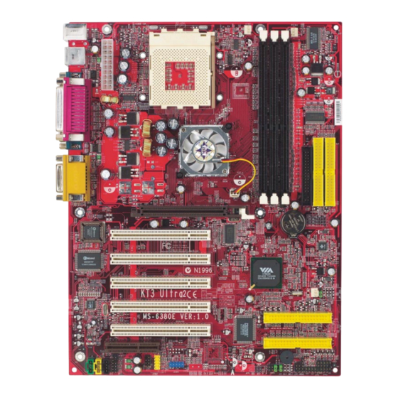
Page 11: Mainboard Layout
Chapter 1 Mainboard Layout Top : mouse CFAN1 PSFAN1 Bottom: keyboard SOCKET 462 ports Top : Parallel Port Bottom: COM A COM B K 333 Top : Game port Bottom: Line-Out Line-In NBFAN1 AGP Slot BATT PCI Slot 1 BIOS PCI Slot 2 Winbond W83697HF... -
Page 12: Getting Started
Getting Started Top : mouse CFAN1 PSFAN1 Bottom: keyboard SOCKET 462 ports Top : Parallel Port Bottom: COM A COM B VT333 Top : Game port Bottom: Line-Out NBFAN1 Line-In AGP Slot BATT PCI Slot 1 BIOS PCI Slot 2 Winbond W83697HF PCI Slot 3... -
Page 13: Quick Components Guide
Chapter 1 Quick Components Guide Component Function Reference JWR1 ATX 20-pin power connector See p. 2-7 JKBMS1 Mouse connector See p. 2-8 JKBMS1 Keyboard connector See p. 2-9 COM A & COM B Serial port connector See p. 2-10 L P T 1 Parallel port connector See p. -
Page 14: Msi Special Features
Getting Started MSI Special Features PC Alert™ III The PC Alert III is a utility you can find in the CD-ROM disk. The utility is just like your PC doctor that can de- tect the following PC hardware status during real time operation: * monitor CPU &... -
Page 15: Fuzzy Logic™ 4
After rebooting, click Turbo to apply the test result. Click Default to restore the default values. Features: MSI Logo links to the MSI Web site CPU Speed allows users to adjust the CPU speed through CPU Multiplier and FSB... -
Page 16: Live Bios™/Live Driver
Web site. To use the function, you need to install the “MSI Live Update Series 2” application. After the installation, the “MSI Live Update Series 2” icon (as shown on the right) will appear on the screen. Double click the “MSI Live Update Series 2” icon, and the following screen will appear: Five buttons are placed on the leftmost pane of the screen. -
Page 17: D-Bracket™ 2(Optional)
Chapter 1 D-Bracket™ 2 (optional) D-Bracket™ 2 is an external USB bracket integrating four Diagnostic LEDs, which use graphic signal display to help users understand their system. The LEDs provide up to 16 combinations of signals to debug the system. The 4 LEDs can debug all problems that fail the system, such as VGA, RAM or other failures. - Page 18 Getting Started D-Bracket Description Processor Initialization - This will show information regarding the processor (like brand name, system bus, etc…) Testing RTC (Real Time Clock) Initializing Video Interface - This will start detecting CPU clock, checking type of video onboard. Then, detect and initialize the video adapter. BIOS Sign On - This will start showing information about logo, processor brand name, etc….
-
Page 19: S-Bracket (Optional)
Chapter 1 S-Bracket (Optional) S-Bracket is a bracket which provides 2 SPDIF jacks for digital audio transmission and 2 analog Line-Out connectors for additional 4-channel ana- log audio output. With the S-Bracket, your system will be able to perform 6- channel audio operation for wonderful surround sound effect, or connect to Sony &... -
Page 20: Msi Dvd (5.1 Channel)
Dolby Digital format first. To play DVD with 6-channel audio output, you must configure both the MSI DVD application and the audio codec’s software utility. Otherwise, the 6- channel audio function will not work properly. For information on how to select 6-channel mode in the audio software utility, refer to Appendix. - Page 21 Chapter 1 4. Click OK. For more information about MSI DVD, you can refer to the online help coming with the application. To enter the online help: 1. Click on the icon at the bottom-right corner of the control panel.
-
Page 22: Cpu Thermal Protection
Getting Started CPU Thermal Protection Aimed to prevent the CPU from overheating, MSI has developed a CPU Thermal Protection mechanism for AMD Athlon XP CPU platform. This CPU Thermal Protection mechanism works on a thermal signal sensor. If the mecha- nism senses an abnormal temperature rise, it will automatically shut down the system and the CPU temperature will then drop down and resume normal. -
Page 23: Chapter 2. Hardware Setup
Hardware Setup Chapter 2. Hardware Setup Hardware Setup This chapter provides you with the information about hardware setup procedures. While doing the installation, be careful in holding the compo- nents and follow the installation procedures. For some components, if you install in the wrong orientation, the components will not work properly. -
Page 24: Central Processing Unit: Cpu
Chapter 2 Central Processing Unit: CPU ® The mainboard supports AMD Athlon™, Athlon™ XP and Duron™ processors in the 462 pin package. The mainboard uses a CPU socket called Socket A for easy CPU installation. When you are installing the CPU, make sure the CPU has a heat sink and a cooling fan attached on the top to prevent overheating. - Page 25 Hardware Setup Thermal Issue for CPU WARNING! As processor technology pushes to faster speeds and higher performance, thermal management becomes increasingly crucial when building computer systems. Maintaining the proper thermal environment is key to reliable operation. As such, the processor must be maintained in the specified thermal requirements.
-
Page 26: Cpu Core Speed Derivation Procedure
Chapter 2 CPU Core Speed Derivation Procedure CPU Clock 100MHz Core/Bus ratio then CPU core speed Host Clock x Core/Bus ratio 100MHz x 7 700MHz CPU Clock Frequency Selection through BIOS The hardware configuration for CPU clock frequency of the motherboard is set to 100MHz by default. -
Page 27: Memory
Hardware Setup Memory The mainboard provides 3 sockets for 184-pin DDR SDRAM DIMM (Double In-Line Memory Module) modules and supports the memory size up to 3GB. You can install PC2700/DDR333, PC2100/DDR266 or PC1600/DDR200 modules on the DDR DIMM slots (DIMM 1~3). DDR DIMM Slots (DIMM 1~3) Introduction to DDR SDRAM... -
Page 28: Dimm Module Combination
Chapter 2 DIMM Module Combination Install at least one DIMM module on the slots. Memory modules can be installed on the slots in any order. You can install either single- or double- sided modules to meet your own needs. Memory modules can be installed in any combination as follows: Slot Memory Module Total Memory... -
Page 29: Power Supply
Hardware Setup Power Supply The mainboard supports ATX power supply for the power system. Be- fore inserting the power supply connector, always make sure that all compo- nents are installed properly to ensure that no damage will be caused. ATX 20-Pin Power Connector: JWR1 This connector allows you to connect to an ATX power supply. -
Page 30: Back Panel
Chapter 2 Back Panel The Back Panel provides the following connectors: Parallel Midi/Joystick Mouse Keyboard USB COM A COM B L-out L-in MIC Mouse Connector: JKBMS1 ® The mainboard provides a standard PS/2 mouse mini DIN connector for ® ® attaching a PS/2 mouse. -
Page 31: Keyboard Connector
Hardware Setup Keyboard Connector: JKBMS1 ® The mainboard provides a standard PS/2 keyboard mini DIN connector ® ® for attaching a PS/2 keyboard. You can plug a PS/2 keyboard directly into this connector. Pin Definition SIGNAL DESCRIPTION Keyboard DATA Keyboard DATA No connection Ground Keyboard Clock... -
Page 32: Serial Port Connectors: Com A & Com B
Chapter 2 Serial Port Connectors: COM A & COM B The mainboard offers two 9-pin male DIN connectors as serial port COM A & COM B. The ports are 16550A high speed communication ports that send/receive 16 bytes FIFOs. You can attach a serial mouse or other serial devices directly to the connectors. -
Page 33: Parallel Port Connector: Lpt1
Hardware Setup Parallel Port Connector: LPT1 The mainboard provides a 25-pin female centronic connector as LPT. A parallel port is a standard printer port that supports Enhanced Parallel Port (EPP) and Extended Capabilities Parallel Port (ECP) mode. Pin Definition SIGNAL DESCRIPTION STROBE Strobe... -
Page 34: Audio Port Connectors
Chapter 2 Audio Port Connectors Line Out is a connector for Speakers or Headphones. Line In is used for external CD player, Tape player, or other audio devices. Mic is a connector for microphones. 1/8” Stereo Audio Connectors Line Out Line In TIP: The mainboard offers support for 6-channel audio operation and can turn rear audio connectors from 2-channel to 4-/6-... -
Page 35: Connectors
Hardware Setup Connectors The mainboard provides connectors to connect to FDD, IDE HDD, case, modem, LAN, USB Ports, IR module and CPU/System/Power Supply FAN. Floppy Disk Drive Connector: FDD1 The mainboard provides a standard floppy disk drive connector that supports 360K, 720K, 1.2M, 1.44M and 2.88M floppy disk types. FDD1 2-13... -
Page 36: Hard Disk Connectors: Ide1 & Ide2
Chapter 2 Hard Disk Connectors: IDE1 & IDE2 The mainboard has a 32-bit Enhanced PCI IDE and Ultra DMA 33/66/100/ 133 controller that provides PIO mode 0~4, Bus Master, and Ultra DMA 33/66/ 100/133 function. You can connect up to four hard disk drives, CD-ROM, 120MB Floppy (reserved for future BIOS) and other devices. -
Page 37: Ata133 Raid Connectors: Ide3 & Ide4
Hardware Setup ATA133 RAID Connectors: IDE3 & IDE4 The mainboard offers high-end Ultra ATA/133 RAID (0 or 1) hard drive ® interface specifications supported through Promise PDC20276 controller . The Ultra ATA/133 interface boosts data transfer rates between the com- puter and the hard drive up to 133 megabytes (MB) per second. -
Page 38: Fan Power Connectors: Cfan1/Sfan1/Psfan1/Nbfan1
Chapter 2 Fan Power Connectors: CFAN1/SFAN1/PSFAN1/NBFAN1 The CFAN1 (processor fan), SFAN1 (system fan), PSFAN1 (power sup- ply fan) and NBFAN1 (chipset fan) support system cooling fan with +12V. It supports three-pin head connector. When connecting the wire to the connectors, always take note that the red wire is the positive and should be connected to the +12V, the black wire is Ground and should be connected to GND. -
Page 39: Front Panel Connectors: Jfp1 & Jfp2
Hardware Setup Front Panel Connectors: JFP1 & JFP2 The mainboard provides two front panel connectors for electrical con- nection to the front panel switches and LEDs. JFP1 and FJP2 are compliant ® with Intel Front Panel I/O Connectivity Design Guide. Power Power Switch... -
Page 40: Front Panel Audio Connector: Jaud1
Chapter 2 Front Panel Audio Connector: JAUD1 The JAUD1 front panel audio connector allows you to connect to the ® front panel audio and is compliant with Intel Front Panel I/O Connectivity Design Guide. JAUD1 Pin Definition SIGNAL DESCRIPTION AUD_MIC Front panel microphone input signal AUD_GND Ground used by analog audio circuits... -
Page 41: Front Usb Connectors: Jusb2/3
Hardware Setup Front USB Connectors: JUSB2/3 The mainboard provides two USB 2.0 pin headers JUSB2 & JUSB3 ® (optional USB 2.0 bracket available) that are compliant with Intel I/O Connec- tivity Design Guide. USB 2.0 technology increases data transfer rate up to a maximum throughput of 480Mbps, which is forty times faster than USB 1.1, and is ideal for connecting high-speed USB interface peripherals such as USB HDD, digital cameras, MP3 players, printers, modems and the like. - Page 42 Chapter 2 To Attach the Optional USB 2.0 Ports: 1. Take out the USB 2.0 bracket 2. Locate the blue USB pinheader (JUSB3) on the motherboard. 3. Connect the USB cable from USB 2.0 bracket to the JUSB3 pinheader. Connected to JUSB3 (the USB pinheader in blue color) USB 2.0 Bracket This USB 2.0 port will not function when a...
-
Page 43: Cd-In Connector: Jcd
Hardware Setup CD-In Connector: JCD The connector is for CD-ROM audio connector. Aux Line-In Connector: JAUX (optional) The connector is for DVD add-on card with Line-in connector. Modem-In Connector: JMDM (optional) The connector is for modem with internal audio connector. Phone_In Mono_Out JAUX... -
Page 44: D-Bracket™ Connector: Jled
Chapter 2 D-Bracket™ 2 Connector: JLED The mainboard comes with a JLED connector for you to connect to D- Bracket™ 2. D-Bracket™ 2 is a USB Bracket integrating four LEDs and allows users to identify system problem through 16 various combinations of LED signals. -
Page 45: S-Bracket Connector: Jsp3
Hardware Setup S-Bracket Connector: JSP3 The connector allows you to connect a S-Bracket for Sony & Philips Digital Interface (SPDIF). The S-Bracket offers 2 SPDIF jacks for digital audio transmission (one for optical fiber connection and the other for coaxial), and 2 analog Line-Out jacks for 4-channel audio output. -
Page 46: Irda Infrared Module Header: Jir1
Chapter 2 IrDA Infrared Module Header: JIR1 The connector allows you to connect to IrDA Infrared module. You must configure the setting through the BIOS setup to use the IR function. JIR1 is ® compliant with Intel Front Panel I/O Connectivity Design Guide. JIR1 Pin Definition Signal VCC5... -
Page 47: Wake On Ring Connector: Jmdm1
Hardware Setup Wake On Ring Connector: JMDM1 This connector allows you to connect to a modem card with Wake On Ring function. The connector will power up the system when a signal is ® received through the modem card. JMDM1 is compliant with Intel Front Panel I/O Connectivity Design Guide. -
Page 48: Bluetooth Connector: Jbt2 (Optional)
Chapter 2 Bluetooth Connector: JBT2 (optional) This connector is used to connect a bluetooth module for wireless connection. JBT2 JBT2 Pin Definition SIGNAL SIGNAL 5VDUAL 3VDUAL D+ (USB signal) D- (USB signal) Note: 1. Because the bluetooth connector shares the USB interface with blue-colored USB2.0 connector, the bottommost USB2.0 port will not function when you attach a bluetooth module to this connector. -
Page 49: Jumpers
Hardware Setup Jumpers The motherboard provides the following jumpers for you to set the computer’s function. This section will explain how to change your motherboard’s function through the use of jumpers. Clear CMOS Jumper: JBAT1 There is a CMOS RAM on board that has a power supply from external battery to keep the data of system configuration. -
Page 50: Slots
Chapter 2 Slots The motherboard provides one AGP slot, five 32-bit Master PCI bus slots, and one CNR slot. AGP Slot PCI Slots CNR Slot AGP (Accelerated Graphics Port) Slot The AGP slot allows you to insert the AGP graphics card. AGP is an interface specification designed for the throughput demands of 3D graphics. -
Page 51: Pci Interrupt Request Routing
Hardware Setup PCI Interrupt Request Routing The IRQ, abbreviation of interrupt request line and pronounced I-R-Q, are hardware lines over which devices can send interrupt signals to the microprocessor. The “AGP/PCI/Promise” IRQ pins are typically connected to the PCI bus INT A# ~ INT D# pins as follows: Order 1 Order 2 Order 3... -
Page 52: Chapter 3. Bios Setup
BIOS Setup Chapter 3. BIOS Setup BIOS Setup This chapter provides information on the BIOS Setup program and allows you to configure the system for optimum use. You may need to run the Setup program when: An error message appears on the screen during the system booting up, and requests you to run SETUP. -
Page 53: Entering Setup
Chapter 3 Entering Setup Power on the computer and the system will start POST (Power On Self Test) process. When the message below appears on the screen, press <DEL> key to enter Setup. DEL:Setup F11:Boot Menu F12:Network boot TAB:Logo If the message disappears before you respond and you still wish to enter Setup, restart the system by turning it OFF and On or pressing the RESET button. -
Page 54: Control Keys
BIOS Setup Control Keys < > Move to the previous item < > Move to the next item Move to the item in the left hand < > Move to the item in the right hand < > <Enter> Select the item <Esc>... -
Page 55: The Main Menu
Chapter 3 The Main Menu Once you enter AMIBIOS NEW SETUP UTILITY, the Main Menu will appear on the screen. The Main Menu displays twelve configurable functions and two exit choices. Use arrow keys to move among the items and press <Enter> to enter the sub-menu. - Page 56 BIOS Setup Integrated Peripherals Use this menu to specify your settings for integrated peripherals. PC Health Status This entry shows your PC health status. Frequency/Voltage Control Use this menu to specify your settings for frequency/voltage control. Set Supervisor Password Use this menu to set Supervisor Password. Set User Password Use this menu to set User Password.
-
Page 57: Standard Cmos Features
Chapter 3 Standard CMOS Features The items inside STANDARD CMOS SETUP menu are divided into 9 categories. Each category includes none, one or more setup items. Use the arrow keys to highlight the item you want to modify and use the <PgUp> or <PgDn> keys to switch to the value you prefer. - Page 58 BIOS Setup Pri Master/Pri Slave/Sec Master/Sec Slave Press PgUp/<+> or PgDn/<-> to select the hard disk drive type. The specifica- tion of hard disk drive will show up on the right hand according to your selection. Type Select how to define the HDD parameters Cylinders Enter cylinder number Heads...
-
Page 59: Advanced Bios Features
Chapter 3 Advanced BIOS Features Quick Boot Setting the item to Enabled allows the system to boot within 5 seconds since it will skip some check items. Available options: Enabled, Disabled. Full Screen Logo Show This item enables you to show the company logo on the bootup screen. Set- tings are: Enabled Shows a still image (logo) on the full screen at boot. - Page 60 BIOS Setup 1st/2nd/3rd Boot Device The items allow you to set the sequence of boot devices where AMIBIOS attempts to load the operating system. The settings are: IDE-0 The system will boot from the first HDD. IDE-1 The system will boot from the second HDD. IDE-2 The system will boot from the third HDD.
- Page 61 Chapter 3 Note: Available settings for “1st/2nd/3rd Boot Device” vary depend- ing on the bootable devices you have installed. For example, if you did not install a floppy drive, the setting “Floppy” does not show up. Try Other Boot Devices Setting the option to Yes allows the system to try to boot from other devices if the system fails to boot from the 1st/2nd/3rd boot device.
- Page 62 BIOS Setup Option Description Setup The password prompt appears only when end users try to run Setup. Always A password prompt appears every time when the computer is powered on or when end users try to run Setup. Boot To OS/2 ®...
- Page 63 Chapter 3 APIC Function This field is used to enable or disable the APIC (Advanced Programmable Interrupt Controller). Due to compliance to PC2001 design guide, the system is able to run in APIC mode. Enabling APIC mode will expand available IRQs resources for the system.
-
Page 64: Advanced Chipset Features
BIOS Setup Advanced Chipset Features Note: Change these settings only if you are familiar with the chipset. DRAM Timing Control Press <Enter> and the following sub-menu appears. Current Host Clock This item shows the current CPU frequency. 3-13... - Page 65 Chapter 3 Configure SDRAM Timing by Selects whether DRAM timing is controlled by the SPD (Serial Presence Detect) EEPROM on the DRAM module. Setting to SPD enables SDRAM Frequency, SDRAM CAS# Latency, Row Precharge Time, RAS Pulse Width, RAS to CAS Delay and SDRAM Bank Interleave automatically to be determined by BIOS based on the configurations on the SPD.
- Page 66 BIOS Setup SDRAM Bank Interleave This field selects 2-bank or 4-bank interleave for the installed SDRAM. Disable the function if 16MB SDRAM is installed. Settings: Disabled, 2-Way and 4-Way. SDRAM Burst Length This setting allows you to set the size of Burst-Length for DRAM. Bursting feature is a technique that DRAM itself predicts the address of the next memory location to be accessed after the first address is accessed.
- Page 67 Chapter 3 AGP Comp. Driving This field is used to adjust the AGP driving force. Selecting Manual allows you to select an AGP driving force in Manual AGP Comp. Driving. It is strongly recommended to select Auto to avoid causing any system error.
- Page 68 BIOS Setup transactions cycles so that transactions to and from the ISA bus are buffered and PCI bus can perform other transactions while the ISA transaction is underway. Select Enabled to support compliance with PCI specification ver- sion 2.1. Setting options: Enabled, Disabled. 3-17...
-
Page 69: Power Management Features
Chapter 3 Power Management Features (S3-related functions described in this section are available only when your BIOS supports S3 sleep mode.) IPCA Function This item is to activate the ACPI (Advanced Configuration and Power Man- agement Interface) function. If your operating system is ACPI-aware, such as Windows 98SE/2000/ME, select Yes. - Page 70 BIOS Setup The information stored in memory will be used to restore the system when a “wake up” event occurs. Auto BIOS determines the best mode automatically. Call VGA at S3 Resuming Selecting Enabled allows BIOS to call VGA BIOS to initialize the VGA card when system wakes up (resume) from S3 sleep state.
- Page 71 Chapter 3 CPU Critical Temperature If the CPU temperature reaches the upper limit preset in this setting, the warn- ing mechanism will be activated. This helps you to prevent the CPU overheat- ing problem. Power Button Function This feature sets the function of the power button. Settings are: On/Off The power button functions as normal power off button.
- Page 72 BIOS Setup Resume On KBC (with “Wake-Up Key” and “Wake-Up Password”), Resume On PS/2 Mouse These fields specify whether the system will be awakened from power saving modes when activity or input signal of the specified hardware peripheral or component is detected. Settings: S3, Disabled. Note: 1.
-
Page 73: Pnp/Pci Configurations
Chapter 3 PNP/PCI Configurations This section describes configuring the PCI bus system and PnP (Plug & Play) feature. PCI, or Peripheral Component Interconnect, is a system which allows I/O devices to operate at speeds nearing the speed the CPU itself uses when communicating with its special components. - Page 74 BIOS Setup PCI Latency Timer This item controls how long each PCI device can hold the bus before another takes over. When set to higher values, every PCI device can conduct transac- tions for a longer time and thus improve the effective PCI bandwidth. For better PCI performance, you should set the item to higher values.
-
Page 75: Integrated Peripherals
Chapter 3 Integrated Peripherals FDC Function This is used to enable or disable the onboard Floppy controller. Option Description Auto BIOS will automatically determine whether to enable the onboard Floppy controller or not. Enabled Enables the onboard Floppy controller. Disabled Disables the onboard Floppy controller. - Page 76 BIOS Setup IR Pin Select Set to IRRX/IRTX when using an internal IR module connected to the IR header. Set to SINB/SOUTB. when connecting an IR adapter to COM B. OnBoard Parallel Port This field specifies the base I/O port address of the onboard parallel port. Selecting Auto allows AMIBIOS to automatically determine the correct base I/O port address.
- Page 77 Chapter 3 OnBoard ATA133 RAID (Optional) This setting controls the onboard RAID controller. The field appears only when your mainboard supports IDE RAID function. Setting options: Disabled, Enabled. AC’97 Audio The item is used to enable or disable the onboard AC’97 (Audio Codec’97) controller.
-
Page 78: Pc Health Status
BIOS Setup PC Health Status This section shows the status of your CPU, fan, overall system status, etc. Monitor function is available only if there is hardware monitoring mechanism onboard. Chassis Intrusion The field enables or disables the feature of recording the chassis intrusion status and issuing a warning message if the chassis is once opened. -
Page 79: Frequency/Voltage Control
Chapter 3 Frequency/Voltage Control Use this menu to specify your settings for frequency/voltage control. Spread Spectrum When the motherboard’s clock generator pulses, the extreme values (spikes) of the pulses creates EMI (Electromagnetic Interference). The Spread Spec- trum function reduces the EMI generated by modulating the pulses so that the spikes of the pulses are reduced to flatter curves. - Page 80 BIOS Setup CPU Ratio/Vcore (V) The items are used to adjust the CPU clock multiplier (ratio) and CPU core voltage (Vcore). These fields provide users a tool to overclock the system. Warning: Changing CPU Ratio/Vcore could result in the instabil- ity of the system;...
-
Page 81: Set Supervisor/User Password
Chapter 3 Set Supervisor/User Password When you select this function, a message as below will appear on the screen: Type the password, up to six characters in length, and press <Enter>. The password typed now will replace any previously set password from CMOS memory. -
Page 82: Load High Performance/Bios Setup Defaults
BIOS Setup Load High Performance/BIOS Setup Defaults The two options on the main menu allow users to restore all of the BIOS settings to High Performance defaults or BIOS Setup defaults. The High Per- formance Defaults are the values set by the mainboard manufacturer for the best system performance but probably will cause a stability issue. -
Page 83: Using 4- Or 6-Channel Audio Function
Using 4- or 6-Channel Audio Function... - Page 84 Appendix ® ® ® Click here...
- Page 85 Using 4- or 6-Channel Audio Function Click here Select this option Click here...
- Page 86 Appendix Note:...
- Page 87 Using 4- or 6-Channel Audio Function...
- Page 88 Appendix...
- Page 89 Using 4- or 6-Channel Audio Function Plug...
- Page 90 Appendix...
- Page 91 Using 4- or 6-Channel Audio Function...
- Page 92 Appendix Note: A-10...
- Page 93 Using 4- or 6-Channel Audio Function Note: A-11...
- Page 94 Appendix A-12...
-
Page 95: Glossary
Glossary... - Page 96 Glossary Dynamic RAM (DRAM) Memory Technologies Peak Type First Used Clock Rate Bus* Width Volts Bandwidth FPM (60,70ns) 1990 25MHz 64 bits 200 MBps EDO (50,60,70ns) 1994 40MHz 64 bits 320 MBps SDRAM (66MHz) 1996 66MHz 64 bits 528 MBps 3.3v SDRAM (100MHz) 1998...
- Page 97 Glossary...
- Page 98 Glossary...