Table of Contents
Advertisement
Quick Links
Advertisement
Table of Contents

Related Manuals for MSI 5000V Master-A6


Summary of Contents for MSI 5000V Master-A6
- Page 1 5000V Master MS-9638 (V1.X) Server Board G52-96381X1...
-
Page 2: Trademarks
Alternatively, please try the following help resources for further guidance. Visit the MSI website at http://www.msi.com.tw/program/service/faq/ faq/esc_faq_list.php for FAQ, technical guide, BIOS updates, driver updates, and other information. Contact our technical staff at http://support.msi.com.tw/. -
Page 3: Safety Instructions
Safety Instructions Always read the safety instructions carefully. Keep this User’s Manual for future reference. Keep this equipment away from humidity. Lay this equipment on a reliable flat surface before setting it up. The openings on the enclosure are for air convection hence protects the equip- ment from overheating. -
Page 4: Fcc-B Radio Frequency Interference Statement
FCC-B Radio Frequency Interference Statement T h is eq uip men t h as been tested and found to c omply with the limits for a Class B digital device, pursuant to Part 15 of the FCC Rules. These limits are designed to provide reasonable protection against harmful interference in a residential installation. -
Page 5: Weee (Waste Electrical And Electronic Equipment) Statement
WEEE (Waste Electrical and Electronic Equipment) Statement... -
Page 8: Table Of Contents
CONTENTS Copyright Notice ......................ii Trademarks ........................ii Revision History ......................ii Technical Support ......................ii Safety Instructions ......................iii FCC-B Radio Frequency Interference Statement ............iv W EEE (Waste Electrical and Electronic Equipment) Statement ........v Chapter 1 Getting Started ..................1-1 Mainboard Specifications ................... - Page 9 BIOS Write Protect Jumper: JBIOS1 ............2-17 LAN Jumper: JLANDIS1, JLANDIS2 ............2-17 Slots ........................2-18 PCI (Peripheral Component Interconnect) Slot ........2-18 Chapter 3 BIOS Setup ..................... 3-1 Entering Setup ..................... 3-2 Control Keys ....................3-3 Getting Help ....................3-3 General Help <F1>...
- Page 10 Selecting the Management Type ..............C-3 SCSI Bus Interface Definitions ..............C-4 Configure/View SCSI Settings ................C-5 Additional Options ..................C-5 BIOS Information ..................C-8 Disk Utilities ......................C-8...
-
Page 11: Chapter 1 Getting Started
Getting Started Chapter 1 Getting Started Thank you for choosing the 5000V Master (MS-9638 v1.X), an excellent SSI CEB server board from MSI. ® Based on the innovative Intel 5000V & ESB2E chipsets for optimal system efficiency, the 5000V Master ac- ®... -
Page 12: Mainboard Specifications
MS-9638 Server Board Mainboard Specifications Processor Support ® ® - Supports dual Intel Xeon (Dempsey/W oodcrest/Clovertown) processors in Socket LGA771 - Supports Intel EM64T, DEP (XD bit) Supported FSB - FSB 667/1066/1333MHz Chipset ® - Northbridge: Intel 5000V ® - Southbridge: Intel ESB2E M emory Support - 4 DDRII 533/667 FB-DIMM (Fully Buffered Dual-In-line DIMM) slots... - Page 13 - 2 x 100MHz PCI-X slots (the green one for ZCR) - 1 x PCI-Express x8 slot - 1 x PCI-Express x8 slot (x4 transfer speed) Form Factor - SSI CEB: 12” X 10.5” M ounting - 7 mounting holes For more information on compatible components, please visit http://www.msi.com.tw/program/products/server/svr/pro_svr_qvl.php...
-
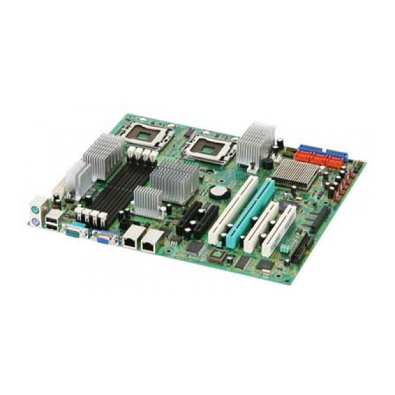
Page 14: Mainboard Layout
MS-9638 Server Board Mainboard Layout CPU1 T: M ouse B: Keybo ard JPWR1 JPWR2 SYSFAN1 Ports FBD12 FBD11 FBD02 FBD01 CPU2 COM2 Int el 5000V LAN1 LAN 2 PCIE1 BATT PCIE2 Winbo bd W836 27HG-AW PCIX1 CPUFA N1 JUSB1 JUSB2 CPUFAN2 PCIX2 BIOS... -
Page 15: Chapter 2 Hardware Setup
Hardware Setup Chapter 2 Hardware Setup This chapter provides you with the information about hardware setup procedures. While doing the installation, be careful in holding the components and follow the installation procedures. For some components, if you install in the wrong orientation, the components will not work properly. -
Page 16: Quick Components Guide
MS-9638 Server Board Quick Components Guide DDRII DIMMs, p.2-6 Back Panel JPWR2, p.2-8 SYSFAN1, I/O, p.2-9 JPWR1, p.2-8 p.2-12 CPU, p.2-3 COM2, p.2-14 P C I - C l a s s Slots, p.2-18 CPUFAN1/2, p.2-12 JBIOS1, p.2-17 JUSB1/2, p.2-14 IDE1, p.2-10 JLANDIS1/2,... -
Page 17: Cpu (Central Processing Unit)
CPU from overheating. If you do not have a CPU cooler, contact your dealer to purchase and install them before turning on the computer. For the latest information about CPU, please visit http://www.msi.com.tw/program/ products/server/svr/pro_svr_qvl.php. Important 1. -
Page 18: Installing The Lga771 Cpu
MS-9638 Server Board Installing the LGA771 CPU 1. Locate the CPU socket. 2. Raise the load lever up to its full extent. 3. Open the load plate. 4. After confirming the CPU direction (indicated below with red circles) for correct mating, put down the CPU in the socket housing frame. -
Page 19: Installing The Intel Cpu Cooler
Hardware Setup Installing the Intel CPU Cooler 1. Flip over the mainboard and locate the position of the CPU sockets. 2. Install the backplates to the back of the CPU sockets with holes aligned. CPU cooler backplate 3. Install the CPU(s) following the in- 5. -
Page 20: Memory
MS-9638 Server Board Memory The mainboard provides four 240-pin 533/667MHz ECC DDRII FB-DIMM slots to sup- port the maximum of 16GB memory capacity. For more information on compatible components, please visit http://www.msi.com. tw/program/products/server/svr/pro_svr_qvl.php. DDRII 240-pin, 1.8V 64x2=128 pin 56x2=112 pin... -
Page 21: Installing Ddrii Modules
Hardware Setup Installing DDRII Modules 1. The memory module has only one notch on the center and will only fit in the right orientation. 2. Insert the memory module vertically into the DIMM slot. Then push it in until the golden finger on the memory module is deeply inserted in the DIMM slot. -
Page 22: Power Supply
MS-9638 Server Board Power Supply SSI 24-Pin System Power Connector: JPWR2 This connector allows you to connect to an SSI power supply. To connect to the SSI power supply, make sure the plug of the power supply is inserted in the proper orientation and the pins are aligned. -
Page 23: Back Panel
Hardware Setup Back Panel M ou se USB Ports Keyboard Serial Port VGA Port M ouse/Keyboard Connector ® ® The standard PS/2 mouse/keyboard DIN connector is for a PS/2 mouse/keyboard. USB Ports The OHCI (Open Host Controller Interface) Universal Serial Bus root is for attaching USB devices such as keyboard, mouse, or other USB-compatible devices. -
Page 24: Connectors
MS-9638 Server Board Connectors Floppy Disk Drive Connector: FDD1 The mainboard provides a standard floppy disk drive connector. FDD1 ATA100 Hard Disk Connector: IDE1 The mainboard has a 32-bit Enhanced PCI IDE and Ultra DMA 66/100 controller that provides PIO mode 0~4, Bus Master, and Ultra DMA 66/100 function. You can connect hard disk drives, CD-ROM and other IDE devices. -
Page 25: Serial Ata Connectors: Sata0 ~ Sata5
Hardware Setup Serial ATA Connectors: SATA0 ~ SATA5 SATA0 ~ SATA5 are high-speed SATA II interface ports and support SATA II data rates of 300MB/s. Each SATA II connector can connect to 1 hard disk device and is fully compliant with Serial ATA 2.0 specifications. Serial ATA cable Take out the dust cover and connect to the hard... -
Page 26: Chassis Intrusion Switch Connector: Jci1
MS-9638 Server Board Chassis Intrusion Switch Connector: JCI1 This connector connects to a 2-pin chassis switch. If the chassis is opened, the switch will be short. The system will record this status and show a warning mes- sage on the screen. To clear the warning, you must enter the BIOS utility and clear the record. -
Page 27: Lan Led Connectors: Jact1, Jact2
Hardware Setup LAN LED Connectors: JACT1, JACT2 The LAN LED connectors are used to connect to LAN LEDs, which show the activity of the LAN. The JACT1 is for the LAN 1 jack and the JACT2 is for the LAN2 jack. Both LAN1 &... -
Page 28: Serial Port Connector: Com 2
MS-9638 Server Board Serial Port Connector: COM 2 The mainboard provides one 9-pin header as serial port COM 2. The port is a 16550A high speed communication port that sends/receives 16 bytes FIFOs. You can attach a serial mouse or other serial devices directly to it. Pin Definition SIGNAL DESCRIPTION... -
Page 29: Ultra320 Scsi Connector: Scsi1
Hardware Setup Ultra320 SCSI Connector: SCSI1 SCSI (Small Computer System Interface) is a parallel interface standard for attaching peripheral devices to computers. Ultra320 SCSI is the seventh generation of SCSI I/O technology, and has a maximum data rate speed of 320 MB/sec. SCSI’s commitment to backward compatibility and legacy support are the primary reasons for its durabil- ity as an I/O interface, making SCSI the industry standard for disk drive connection in virtually all high-performance servers. -
Page 30: Jumpers
MS-9638 Server Board Jumpers Clear CMOS Jumper: JBAT1 There is a CMOS RAM onboard that has a power supply from external battery to keep the data of system configuration. With the CMOS RAM, the system can automatically boot OS every time it is turned on. If you want to clear the system configuration, set the JBAT1 (Clear CMOS Jumper ) to clear data. -
Page 31: Bios Recovery Jumper: J9
Hardware Setup BIOS Recovery Jumper: J9 Users can short connect pin#2-3 to recover the system BIOS. W hen the system is done with the job, the buzzer will beep to remind users to set the jumper to its normal state (pin#1-2 short connected). Normal Recovery BIOS Write Protect Jumper: JBIOS1... -
Page 32: Slots
MS-9638 Server Board Slots PCI (Peripheral Component Interconnect) Slot The PCI-class slots support LAN cards, SCSI cards, USB cards, VGA cards, and other add-on cards that comply with PCI specifications. PCI Express architecture provides a high performance I/O infrastructure for Desktop Platforms with transfer rates starting at 2.5 Giga transfers per second over a PCI Express x1 lane for Gigabit Ethernet, TV Tuners, 1394 controllers, and general pur- pose I/O. -
Page 33: Chapter 3 Bios Setup
BIOS Setup Chapter 3 BIOS Setup This chapter provides information on the BIOS Setup program and allows you to configure the system for optimum use. You may need to run the Setup program when: ² An error message appears on the screen during the system booting up, and requests you to run SETUP. -
Page 34: Entering Setup
MS-9638 Server Board Entering Setup Power on the computer and the system will start POST (Power On Self Test) process. W hen the message below appears on the screen, press <F2> key to enter Setup. Press <F2> to enter SETUP If the message disappears before you respond and you still wish to enter Setup, restart the system by turning it OFF and On or pressing the RESET button. -
Page 35: Control Keys
BIOS Setup Control Keys Select Items Select Menus Select Sub-menus Enter Exit Change Values Help Setup Defaults <F9> Save and Exit <F10> Getting Help After entering the Setup menu, the first menu you will see is the Main Menu. M ain M enu The main menu lists the setup functions you can make changes to. -
Page 36: The Menu Bar
MS-9638 Server Board The Menu Bar Main Use this menu for basic system configurations, such as time, date etc. Advanced Use this menu to set up the items of special enhanced features available on your system’s chipset. Security Use this menu to set Supervisor and User Passwords. Power Use this menu to specify your settings for power management. -
Page 37: Main
BIOS Setup Main System Time (hh:mm:ss) The time format is <Hour> <Minute> <Second>. System Date (mm:dd:yy) The date format is <Month> <Date> <Year>. Legacy Diskette A This setting allows you to set the type of floppy drives installed. IDE Channel 0 Master/Slave, SATA Port 1/2/3/4 [Type] Press <+>... - Page 38 MS-9638 Server Board [Tranfer Mode] Selects the method for transferring the data between the hard disk and system memory [Ultra DMA Mode] Indicates the type of Ultra DMA Boot Features The sub-menu is used to configure system boot-up features. Floppy Check This setting causes the BIOS to search for floppy disk drives at boot time.
- Page 39 BIOS Setup System Information Press <Enter> to view the hardware specifications of your system. System M emory, Extended M emory These items show the memory status of the system. (Read-only)
-
Page 40: Advanced
MS-9638 Server Board Advanced Reset Configuration Data Select [Yes] if you want to clear the Extended System configuration Data (ESCD) area. Large Disk Access M ode Defaulting this setting to [DOS] will create a Translated FDPT. Compatible ill-behaved applications will operate correctly when [DOS] is selected. Setting to [Other] will create a Standard FDPT. - Page 41 BIOS Setup Advanced Chipset Control Press <Enter> to enter the sub-menu and the following screen appears: USB Host Controller This setting disables/enables the onboard USB host controller. IOAT Support This field enables Intel I/O Acceleration Technology which transfers data more efficiently.
- Page 42 MS-9638 Server Board [Enhanced] SATA and PATA drives are auto-detected and placed (non-AHCI) in Native IDE mode. SATA RAID Enable This feature allows users to enable or disable the RAID function for each SATA hard disk drive. SATA AHCI Enable This setting disables/enables Enhanced AHCI mode.
- Page 43 BIOS Setup Advanced Processor Options Press <Enter> to enter the sub-menu and the following screen appears: Hyperthreading (auto detect function for Intel Dempsey CPU) The processor uses Hyper-Threading technology to increase transaction rates and reduces end-user response times. The technology treats the two cores inside the processor as two logical processors that can execute instructions simultaneously.
- Page 44 MS-9638 Server Board Thermal M anagement 2 (auto detect function) ® This setting specifies the thermal technologies implemented in the Intel processor. C1 Enhanced Mode This item allows you to enable/disable the C1E power management feature which can drop clock speed and voltage on the processor. Execute Disable Bit Intel's Execute Disable Bit functionality can prevent certain classes of malicious "buffer overflow"...
- Page 45 BIOS Setup Floppy Disk Controller Select [Enabled] if your system has a floppy disk controller (FDD) installed on the system board and you wish to use it. If you install add-on FDC or the system has no floppy drive, select [Disabled] in this field. Onboard Device Control Press <Enter>...
- Page 46 MS-9638 Server Board Console Redirection Com Port Address This setting enables/disables the Com port address for console connection. Baud Rate This setting specifies the transfer rate (bits per second) of Console Redirection. Console Type This setting specifies the console type. Flow Control This feature allows you to enable flow control.
- Page 47 BIOS Setup DM I Event Logging Press <Enter> to enter the sub-menu and the following screen appears: Event log validity/capacity These items indicate the status of Event log validity and capacity. View DMI event log These item allows you to view the content of the DMI event log. Event Logging This function is used to log DMI events.
- Page 48 MS-9638 Server Board Security Supervisor Password Is, User Password Is These items indicate the status of password settings. Set Supervisor Password Supervisor Password controls access to the BIOS Setup utility. Set User Password User Password controls access to the system at boot. Password on Boot Choosing [Enabled] requires a password on boot.
-
Page 49: Power
BIOS Setup Power Important S3-related functions are available only when your BIOS supports S3 sleep mode. Power Button Function This feature allows users to configure the power button function. Settings are: [Instant-Off] The power button functions as a normal power-on/-off button. - Page 50 MS-9638 Server Board [Last State] Restores the system to the previous status before power failure or interrupt occurred. Resume On M odem Ring The item specifies how the system will be awakened from power saving mode when input signal of the Modem Ring is detected. Resume On Time Select [On] to wake up the system at predetermined time.
-
Page 51: Pc Health
BIOS Setup PC Health Fan & Temperature Menu These items display the current temperatures and fans’ speeds of the system. Auto FAN Speed Control This item enables/disables the Smart Fan feature (SFAN1 & SFAN4 excluded). Smart Fan is an excellent feature which will adjust the CPU and system fan speed automati- cally depending on the current CPU and system temperature, avoiding the overheat- ing to damage your system. - Page 52 MS-9638 Server Board CPU1 Target Temp, CPU2 Target Temp You can select a fan value here. If the current temperature reaches to the minimum threshold you set here, the fan will slow down to keep the temperature stable. CPU1 Therm Temp Limit, CPU2 Therm Temp Limit You can select a fan tolerance value here.
-
Page 53: Boot
BIOS Setup Boot These settings allow users to set the priority of the specified devices.You may use the arrow keys ( ) to select the desired device, <+>/<-> key to move it up/down in the priority list, <x> key to exclude or include the device to boot, (Shift + 1) to enable or disable a device, (1 - 4) keys to load default boot sequence. -
Page 54: Exit
MS-9638 Server Board Exit Exit Saving Changes Save changes to CMOS and exit setup. Exit Discarding Changes Abandon all changes and exit setup. Load Setup Defaults Use this menu to load the default values set by the BIOS vendor for stable system performance. -
Page 55: Appendix A Intel Sata Raid (Optional
Intel SATA RAID Appendix A Intel SATA RAID (Optional) The Southbridge provides a hybrid solution that com- bines six independent SATAII ports for support of up to six Serial ATAII (Serial ATAII RAID) drives. It offers RAID level 0 (Striping), RAID level 1 (Mirroring and Duplexing), RAID level 5 (Block Interleaved Distrib- uted Parity), RAID level 10 (A Stripe of Mirrors) and ®... -
Page 56: Introduction
2. All the information/volumes listed in your system might differ from the illustrations in this appendix. 3. RAID support on Linux OS will be changed by vendors. Please contact MSI Sales if you need SATA RAID support on Linux OS. -
Page 57: Bios Configuration
Intel SATA RAID BIOS Configuration The Intel Matrix Storage Manager Option ROM should be integrated with the system BIOS on all motherboards with a supported Intel chipset. The Intel Matrix Stroage Manager Option ROM is the Intel RAID implementation and provides BIOS and DOS disk services. - Page 58 MS-9638 Server Board After pressing the <Ctrl> and <I> keys simultaneously, the following window will appear: 6.2.1002 ESB2 (1) Create RAID Volume Select option 1 “Create RAID Volume” and press <Enter> key. The following screen appears. Then in the Name field, specify a RAID Volume name and then press the <TAB>...
- Page 59 Intel SATA RAID In the Disk field, press <Enter> key and the following screen appears. Use <Space> key to select the disks you want to create for the RAID volume, then click <Enter> key to finish selection. 6.2.1002 ESB2 Then select the strip value for the RAID array by using the “upper arrow” or “down arrow”...
- Page 60 MS-9638 Server Board Important Since you want to create two volumes (Intel Matrix RAID Technology), this default size (maximum) needs to be reduced. Type in a new size for the first volume. As an example: if you want the first volume to span the first half of the two disks, re-type the size to be half of what is shown by default.
- Page 61 Intel SATA RAID (2) Delete RAID Volume Here you can delete the RAID volume, but please be noted that all data on RAID drives will be lost. Important If your system currently boots to RAID and you delete the RAID volume in the Intel RAID Option ROM, your system will become unbootable.
- Page 62 MS-9638 Server Board (3) Reset Disks to Non-RAID Select option 3 Reset Disks to Non-RAID and press <Enter> to delete the RAID volume and remove any RAID structures from the drives. The following screen appears: 6.2.1002 ESB2 Press <Y> key to accept the selection. Important 1.
-
Page 63: Appendix B Adaptec Sata Raid (Optional
Adaptec SATA RAID Appendix B Adaptec SATA RAID (Optional) The Southbridge provides a hybrid solution that com- bines six independent SATAII ports for support of up to six Serial ATAII (Serial ATAII RAID) drives. It offers RAID level 0 (Striping), RAID level 1 (Mirroring and Duplexing) and RAID level 10 (A Stripe of Mirrors). -
Page 64: Introduction
Then toggle to “ Ins tallation ” and, at th e c omm and pr ompt, ty pe “broken_modules=ahci” 4. RAID support on Linux OS will be changed by vendors. Please contact MSI Sales if you need SATA RAID support on Linux OS. -
Page 65: Bios Configuration
Adaptec SATA RAID BIOS Configuration The Adaptec SATA Option ROM should be integrated with the system BIOS on all motherboards with a supported Intel chipset. The Adaptec Option ROM is the Adaptec RAID implementation and provides BIOS and DOS disk services. Please use <Ctrl> + <A>... - Page 66 MS-9638 Server Board After pressing the <Ctrl> and <A> keys simultaneously, the following window will appear: (1) Create RAID Volume Enter Array Configuration Utility. Select option “Create array” and press <Enter> key. The following screen appears.
- Page 67 Adaptec SATA RAID Then in the Select drivers to create Array field, specify the devices and then press the <Enter> key to go to the next field. Use the arrow keys to select the RAID level best suited to your usage model in RAID Level.
- Page 68 MS-9638 Server Board Then Enter the Array Label name, and pressing the <Enter> key to select and advance to the next field. The available values range from 16KB to 64 KB in power of 2 increments. The strip value should be chosen based on the planned drive usage.
- Page 69 Adaptec SATA RAID Enter Manager Arrays to confirm if the creation is finished.
- Page 70 MS-9638 Server Board (2) Delete RAID Volume Here you can delete the RAID volume, but please be noted that all data on RAID drives will be lost. Important If your system currently boots to RAID and you delete the RAID volume in the Adaptec RAID Option ROM, your system will become unbootable.
- Page 71 Adaptec SATA RAID Select [Delete], and press <Enter>. The following screen appears: Press <Y> key to accept the volume deletion.
-
Page 72: Appendix C Scsi Bios (Optional
SCSI BIOS Appendix C SCSI BIOS (Optional) This chapter provides information on the Small Com- puter System Interface (SCSI) BIOS setup utility and allows you to configure the SCSI subsystem for opti- mum use. You may need to run the SCSI BIOS setup utility when: ²... -
Page 73: Entering Scsi Bios
MS-9638 Server Board Entering SCSI BIOS Power on the computer and the system will start POST (Power On Self Test) process. W hen the message below appears on the screen, press <Ctrl> + <A> keys simulta- neously to enter SCSI BIOS utility. vvv Press <Ctrl><A>... -
Page 74: Selecting The Management Type
SCSI BIOS Selecting the Management Type The following screen will appear after you select the SCSI channel you intend to manage. The menu will list two categories for you to choose what to do with the SCSI channel. Move the cursor to the desired function and press <Enter>. AIC-7901 at slot 07, 03:07:00 Would you like to configure the SCSI controller, or run the SCSI Disk Utilities? Select the option and press <Enter>. -
Page 75: Scsi Bus Interface Definitions
MS-9638 Server Board Configure/View SCSI Settings There are 8 items in the “Configure/View SCSI Controller Settings” screen. These items display or allow you to change the SCSI controller’s settings. Use the arrow keys to highlight the item and then press <Enter> to select the value you want in each item or enter each item’s sub-menu screen. -
Page 76: Additional Options
SCSI BIOS Additional Options Boot Device Configuration Press <Enter> to enter the sub-menu screen. Boot Device Configuration Single Image Master SCSI Controller ....AIC-7901 at slot 07 03:07:00 Select SCSI peripheral from which to boot Boot SCSI Controller ......AIC-7901 at slot 07 03:07:00 Boot SCSI ID ........ - Page 77 MS-9638 Server Board SCSI Device Configuration SCSI Device ID Sync Transfer Rate (MB/Sec) ..32 0 32 0 32 0 32 0 32 0 32 0 32 0 32 0 Packetized........Yes Yes Yes Yes Yes Yes Yes Yes QAS..........Yes Yes Yes Yes Yes Yes Yes Yes Initiate Wide Negotiation ....
- Page 78 SCSI BIOS on-at-a-time during bootup, reducing the load on the computer’s power supply. Setting options: [Yes], [No]. BIOS Multiple LUN Support Select Yes when any SCSI device has multiple logical units. Setting options: [Yes], [No]. Include in BIOS Scan Selecting [Yes] allows the SCSI controller to control the SCSI device with its SCSI ID.
-
Page 79: Bios Information
MS-9638 Server Board POST Display Mode The field determines how much information about your SCSI controller and devices appear on the screen during bootup. For the most complete information, choose [Diagnostic]. For a faster boot, select [Silent]. Setting options: [Verbose], [Silent], [Diagnostic]. -
Page 80: Disk Utilities
SCSI BIOS Disk Utilities AIC-7901 at slot 07, 03:07:00 Select SCSI Disk and press <Enter> SCSI ID#0: No device SCSI ID#1: No device SCSI ID#2: No device SCSI ID#3: No device SCSI ID#4: No device SCSI ID#5: No device SCSI ID#6: No device SCSI ID#7: Adaptec AIC-7901... - Page 81 MS-9638 Server Board Important 1. It offers RAID level 0 (Striping), RAID level 1 (Mirroring and Duplexing), and RAID level 10 (A Stripe of Mirrors). 2. When installing SuSE OS under SCSI RAID, once the OS boots from the CD-ROM, select F3 or F5 as requested to add drivers. Then toggle to “Installation”...