Table of Contents
Advertisement
Quick Links
Advertisement
Table of Contents

Related Manuals for MSI K8D Master3-133 FA4R


Summary of Contents for MSI K8D Master3-133 FA4R
- Page 1 K8D Master3-133 Series MS-9161 (v2.X) SSI Server Board G52-S9161X2...
-
Page 2: Fcc-A Radio Frequency Interference Statement
Manual Rev: 2.0 Release Date: July 2004 FCC-A Radio Frequency Interference Statement This equipment has been tested and found to comply with the limits for a class A digital device, pursuant to part 15 of the FCC rules. These limits are designed to provide reasonable protection against harmful interference when the equipment is operated in a commercial environment. -
Page 3: Copyright Notice
If a problem arises with your system and no solution can be obtained from the user’s manual, please contact your place of purchase or local distributor. Alternatively, please try the following help resources for further guidance. Visit the MSI website for FAQ, technical guide, BIOS updates, driver updates, and other information: faq/esc_faq_list.php Contact our technical staff at: support@msi.com.tw... -
Page 4: Safety Instructions
Safety Instructions Always read the safety instructions carefully. Keep this User’s Manual for future reference. Keep this equipment away from humidity. Lay this equipment on a reliable flat surface before setting it up. The openings on the enclosure are for air convection hence protects the equip- ment from overheating. -
Page 5: Table Of Contents
Safety Instructions ... iv Chapter 1. Getting Started ... 1-1 Mainboard Specifications ... 1-2 Mainboard Layout ... 1-5 MSI Special Features ... 1-7 PC Alert™ III ... 1-7 Chapter 2. Hardware Setup ... 2-1 Quick Components Guide ... 2-2 Central Processing Unit: CPU ... 2-3 CPU Installation Procedures for Socket 940 ... - Page 6 I2C Bus Connector: I2CCON1 ... 2-15 Serial Port Connector: COM 2 ... 2-15 System ID Button: J5 ... 2-16 System ID LED: D38 ... 2-16 System ID LED Connector: J10 ... 2-16 System ID Button Connector: J9 ... 2-16 Jumpers ... 2-17 Clear CMOS Jumper: JBAT1 ...
-
Page 7: Chapter 1. Getting Started
Getting Started Thank you for purchasing the K8D Master3-133 Series (MS- 9161), an excellent Server System Infrastructure (SSI) mainboard from MSI. Based on the innovative AMD-8131 PCI-X Tunnel and AMD- 8111 I/O HUB chipsets for optimal system efficiency, K8D Master3-... -
Page 8: Mainboard Specifications
MS-9161 SSI Server Board Mainboard Specifications Target Market Segment Target in the entry-level and mid-range, front-end and general purpose server market segments Supports dual Socket 940 for AMD Opteron AMD x86-64 Technology - AMD’s 64-bit, x86 instruction set extensions - 64-bit integer registers, 48-bit virtual address, 40-bit physical address... -
Page 9: Getting Started
K8D Master3-133-FA4R: - Serial ATA RAID interface supported by Silicon Image SiI 3114 PCI to four-port Serial ATA host controller (with 4 SATA connectors onboard/can connect up to 4 Serial ATA drives) - Ultra ATA/100 Bus Master IDE interface supported by AMD-8111 HyperTransport I/O Hub (with 2 IDE connectors onboard/can connect up to 4 Ultra ATA drives) Onboard Peripherals One floppy port supports two FDDs with 360KB, 720KB, 1.2MB, 1.44MB, and 2. - Page 10 - Integrated TMDS transmitter with support for Digital Flat Panel (DFP) monitors - Onboard 8MB Video SDRAM MSI Reminds You... Please refer to Table 1 for 2D modes supporting both CRT and LCD. The table specifies the minimum memory requirements for various display resolutions, refresh rates and color depths.
-
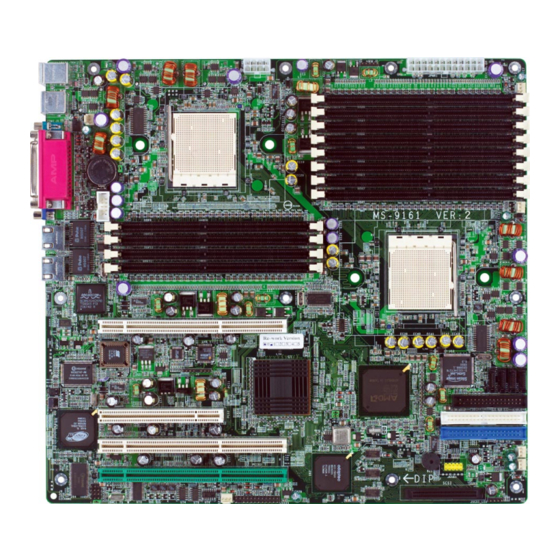
Page 11: Mainboard Layout
PCI 2 RAGE XL PCI X2 PCI X3 Winbond W98643 2DH-6 SFAN2 I2CCON1 JBMC 1 K8D Master3-133-FS (MS-9161 v2.X) SSI Server Board - SCSI interface supported by Adaptec AIC-7901 Ultra-320 SCSI controller Getting Started JPWR2 JPWR1 DDR8 DDR7 DDR6 DDR5... - Page 12 RAGE XL PCI X2 PCI X3 Winbond W98643 2DH-6 I2CCON1 JBMC 1 K8D Master3-133-FA4R (MS-9161 v2.X) SSI Server Board - Serial ATA RAID interface supported by Silicon Image SiI 3114 PCI to four-port Serial ATA host controller JPWR2 DDR8 DDR7 DDR6...
-
Page 13: Msi Special Features
MSI Special Features PC Alert™ III The PC Alert III is a utility you can find in the CD-ROM disk. The utility is just like your PC doctor that can detect the following PC hardware status during real time operation: monitor CPU &... -
Page 14: Chapter 2. Hardware Setup
Chapter 2. Hardware Setup Hardware Setup This chapter provides you with the information about hard- ware setup procedures. While doing the installation, be careful in holding the components and follow the installation procedures. For some components, if you install in the wrong orientation, the compo- nents will not work properly. -
Page 15: Quick Components Guide
MS-9161 SSI Server Board Quick Components Guide JBAT1, p.2-17 CPU2, p.2-3 PFAN1, p.2-12 I/O Ports, p.2-9 JLCD1, p.2-12 COM2, p.2-15 D38, p.2-16 J5, p.2-16 PCI Slots, p.2-19 J10, p.2-16 J11/ I2CCON1, p.2-15 JBMC1, p.2-18 JPWR2, p.2-8 DDR DIMMs, p.2-6 J2, p.2-8 JSSI1, p.2-14... -
Page 16: Central Processing Unit: Cpu
Central Processing Unit: CPU The mainboard supports Single/Dual AMD mainboard uses two CPU sockets called Socket 940 for easy CPU installation. You can install SINGLE or DUAL CPUs on the mainboard to meet your own needs. Keep the following points in mind before installing CPU(s): 1. -
Page 17: Cpu Installation Procedures For Socket 940
MS-9161 SSI Server Board CPU Installation Procedures for Socket 940 Open Lever 1. Make sure that the computer is turned off, and the power cord dis- connected before installing the CPU. 2. Pull the lever sideways away from the socket, and raise it up to a 90-degree angle. - Page 18 If you do not find the heat sink and cooling fan, contact your dealer to purchase and install them before turning on the computer. MSI Reminds You... Overheating Overheating will seriously damage the CPU and system, always make sure the cooling fan can work properly to protect the CPU from overheating.
-
Page 19: Memory
2. Insert the DIMM memory module vertically into the DIMM slot. Then push it in until the golden finger on the memory module is deeply inserted in the socket. MSI Reminds You... You can barely see the golden finger if the module is properly inserted in the socket. -
Page 20: Dimm Configurations
DIMM Configurations Supported DIMM 100MHz Configurations DDR200 64-bit plus ECC 128-bit plus ECC Memory Population Rules The mainboard supports DDR200/266/333/400 memory interface. Each DIMM slot supports up to a maximum size of 2GB. Users can install either single- or double-sided modules depending on their needs. Memory modules can be installed in any combination as follows: Slot Memory module population rules (Dual channel - 128 bits) -
Page 21: Power Supply
JPWR1 JPWR1 Pin Definition SIGNAL +3.3V +3.3V PWR OK 5VSB +12V +12V +3.3V MSI Reminds You... Power supply of 425watt (and up) is highly recommended for system stability. Power Supply J2 Pin Definition SIGNAL +3.3V -12V PS-ON# JPWR2 Pin Definition... -
Page 22: Back Panel
Mouse Keyboard COM1 Mouse/Keyboard Connector Pin5 Mouse/KBD Clock Pin6 NC Pin4 VCC Pin3 GND Pin1 Pin2 NC Mouse/KBD DATA Serial Port 1 2 3 4 5 6 7 8 9 VGA Port Back Panel Parallel USB Ports SIGNAL RJ-45 LAN Jack Activity Indicator SOUT Gigabit LAN Pin Definition... -
Page 23: Connectors
IDE2 (Secondary IDE Connector) IDE2 can also connect a Master and a Slave drive. MSI Reminds You... If you install two hard disks on cable, you must configure the second drive to Slave mode by setting its jumper. Refer to the hard disk docu- mentation supplied by hard disk vendors for jumper setting instructions. -
Page 24: Serial Ata Raid 0, 1, 10 Connectors: Sata1/2/3/4 (Optional)
For more information on Serial ATA RAID 0, 1, 10, please refer to (Silicon Image SiI 3114) Serial ATA RAID 0, 1, 10 Quick User’s Guide. Optional Serial ATA cable MSI Reminds You... Please do not fold the Serial ATA cable into 90-degree angle. Otherwise, the loss of data may occur during transmission. -
Page 25: Lcd Panel Connector: Jlcd1
GND. If the mainboard has a System Hardware Monitor chipset onboard, you must use a specially designed fan with speed sensor to take advantage of the CPU fan control. +12V Sensor CFAN1/2 MSI Reminds You... Always consult the vendors for proper CPU cooling fans. 2-12 SIGNAL GND1 GND0... -
Page 26: Ultra320 Scsi Connector: Scsi (Optional)
Pin Definition JSCSI_LED SIGNAL VCC5 SCSI LED HDD LED VCC5 MSI Reminds You... SCSI LED connects to JSSI1 HDD LED (storage LED) pins. The JSCSI_LED is used to con- nect SCSI card LED signal. Hardware Setup 68-Pin Ultra320 SCSI Connector... -
Page 27: Front Usb Connector: Jusb1
MS-9161 SSI Server Board Front USB Connector: JUSB1 The mainboard provides one USB 1.1 pin header JUSB1 that is compliant with ® Intel I/O Connectivity Design Guide. JUSB1 Front Panel Connector: JSSI1 The mainboard provides one front panel connector for electrical connection to the front panel switches and LEDs. -
Page 28: System Status Led Header: J11
System Status LED Header: J11 Connect an LED to this header and the LED will lighten when the CPU, system, or power fan shuts down. I2C Bus Connector: I2CCON1 The mainboard provides one I2C (also known as I to connect to System Management Bus (SMBus) interface. Serial Port Connector: COM 2 The mainboard provides one 9-pin header as serial port COM 2. -
Page 29: System Id Button: J5
MS-9161 SSI Server Board System ID Button: J5 System ID LED: D38 The J5 system ID button & D38 system ID LED are designed to facilitate the management of two or more MS-9161 systems. When one of the systems crashes,... -
Page 30: Jumpers
JBAT1 (Clear CMOS Jumper ) to clear data. JBAT1 MSI Reminds You... You can clear CMOS by shorting 2-3 pin while the system is off. Then return to 1-2 pin position. Avoid clearing the CMOS while the system is on;... -
Page 31: Pcix Channel A Frequency Jumper: J25
MS-9161 SSI Server Board PCIX Channel A Frequency Jumper: J25 The jumper is used to set the channel A of 64-bit PCI bus (PCIX) to run at PCI- X 66/100MHz or at PCI 66MHz. Channel A includes Giga-bit LAN, SCSI interface, and 64-bit PCIX2/3 slots. -
Page 32: Slots
The motherboard provides one 32-bit Master PCI slot and three 64-bit PCI-X slots. 64-bit PCI-X Slots PCI (Peripheral Component Interconnect) Slots The PCI slots allow you to insert the expansion cards to meet your needs. When adding or removing expansion cards, make sure that you unplug the power supply first. -
Page 33: Pci Interrupt Request Routing
MS-9161 SSI Server Board PCI Interrupt Request Routing The IRQ, acronym of interrupt request line and pronounced I-R-Q, are hard- ware lines over which devices can send interrupt signals to the microprocessor. The PCI IRQ pins are typically connected to the PCI bus pins as follows:... -
Page 34: Chapter 3. Bios Setup
SETUP. You want to change the default settings for customized features. MSI Reminds You... 1. The items under each BIOS category described in this chapter are under continuous update for better system performance. -
Page 35: Entering Setup
MS-9161 SSI Server Board Power on the computer and the system will start POST (Power On Self Test) process. When the message below appears on the screen, press <F2> key to enter Setup. Press F2 to enter SETUP If the message disappears before you respond and you still wish to enter Setup, restart the system by turning it OFF and On or pressing the RESET button. -
Page 36: Getting Help
Getting Help After entering the Setup menu, the first menu you will see is the Main Menu. Main Menu The main menu lists the setup functions you can make changes to. You can use the arrow keys ( to select the item. The on-line description of the highlighted setup function is displayed at the bottom of the screen. -
Page 37: The Menu Bar
MS-9161 SSI Server Board Once you enter PhoenixBIOS Setup Utility, the Main Menu will appear on the screen. On the Main Menu screen, you will see basic BIOS settings including system time & date, and the setup categories the BIOS supplies. Use Arrow keys to move among the items and menus, and make changes to the settings. -
Page 38: The Main Menu
The Main Menu The items inside the Main menu are for basic system information and configuration. Each item includes none, one or more setup items. Use the Up/Down arrow keys or <Tab> to highlight the item or field you want to modify and use the <+> or <->... - Page 39 MS-9161 SSI Server Board provided in the documentation from your hard disk vendor or the system manufacturer. [Type] [Multi-Sector Transfers] [LBA Mode Control] [32-Bit I/O] [Tranfer Mode] [Ultra DMA Mode] Large Disk Access Mode Select [DOS] if you have DOS. Select Other if you have another operating system such as UNIX.
-
Page 40: The Advanced Menu
The Advanced Menu Items in the menu are divided into 7 sub-menus. Each sub-menu provides more settings. To enter the sub-menu, highligh the sub-menu you want to configure and press <Enter>. PhoenixBIOS Setup Utility Main Advanced Installed O/S : Reset Configuration Data : USB Host Controller : USB BIOS Legacy Support : Multiprocessor Specification :... - Page 41 MS-9161 SSI Server Board Multiprocessor Specification This item allows you to configure the MP Specification revision level. Some operating systems will require 1.1 for compatibility reason. Options: [1.4], [1.1]. Quick Boot Mode This feature allows the system skip certain tests while booting. This will decrease the time needed to boot the system.
- Page 42 HPET Timer This item allows you to enable/disable HPET (high precision event timer). Setting to Disabled will turn off the device and remove it from the ACPI namespace. Options: [Enabled], [Disabled]. This is a global enable function for all blocks within CPU core and North Bridge. After loading setup defaults, restart and enter setup to access Dram ECC setup options.
- Page 43 MS-9161 SSI Server Board Advanced Keyboard Configuration NumLock : Keyboard auto-repeat rate : Keyboard auto-repeat dealy : F1 Help Select Item Esc Exit Select Menu NumLock [On] or [Off] turns NumLock on or off at boot up. Options: [On], [Off].
-
Page 44: Bios Setup
PhoenixBIOS Setup Utility Advanced I/O Device Configuration PS/2 Mouse : Floppy Disk Controller : Onboard PCI IDE : Serial port A : Base I/O address : Interrupt : Serial port B : Base I/O address : Interrupt : Parallel Port : Mode : Base I/O address : Interrupt :... - Page 45 MS-9161 SSI Server Board Interrupt It specifies the interrupt for Port A/Port B. Options: [IRQ 3], [IRQ 4]. Parallel Port Setting to [Enabled] allows users to configure the base I/O address and IRQ for the parallel port manually. Options: [Enabled], [Disabled].
- Page 46 PhoenixBIOS Setup Utility Advanced PCI Configuration 8PCIX Slot 1 8PCIX Slot 2 8PCIX Slot 3 8PCI Slot 1 8Onboard LAN Device 8Onboard SCSI Device 8Onboard SATA Device F1 Help Select Item Esc Exit Select Menu PCIX Slot 1, PCIX Slot 2, PCIX Slot 3, PCI Slot 1 The sub-menu is used to configure the specified PCI device.
- Page 47 MS-9161 SSI Server Board Latency Timer Use this feature to minimize guaranteed time slice allotted for bus master in units of PCI bus clocks. Onboard SCSI Device/Onboard SATA Device (Optional) The sub-menu is used to configure the onboard SCSI or SATA device and will show either as Onboard SCSI Device or as Onboard SATA Device depend- ing on the hardware interface integrated onboard.
- Page 48 Com Port Address This feature allows you to enable/disable the Com port on the motherboard. Options: [Disabled], [On-board COM A]. Console connection This feature indicates whether the console is connected directly to the system or a modem is used for connection. Options: [Direct], [Via modem]. Baud Rate It allows you to select delay befor key repeat.
- Page 49 MS-9161 SSI Server Board View DMI event log Press [Enter] to view the contents of the DMI event log. Clear all DMI event logs Setting this to [Yes] will clear the DMI event log after rebooting. Options: [Yes], [No]. Event Logging Select Enabled to allow logging of DMI events.
- Page 50 Clear System Event Log Enabling this selection will force the BIOS to clear the System Event Log on the next boot. Options: [Disabled], [Enabled]. Existing Event Log number It shows the number of existing event log. SYS Firmware Progress Enabling this selection will log POST Progress. Options: [Enabled], [Disabled]. BIOS POST Watchdog Enabling this selection will enable POST watchdog.
-
Page 51: The Security Menu
MS-9161 SSI Server Board The Security Menu This section lets you set security passwords to control access to the system at boot time and/or when entering the BIOS setup program. It also allows you to set virus protection at hard disk boot sector. - Page 52 BIOS Setup Password on boot Choosing [Enabled] requires a password on boot. It requires prior setting of the supervisor password. If the supervisor password is set and this option is disabled, BIOS assumes the user is booting. Options: [Enabled], [Disabled]. Fixed disk boot sector Write protects the boot sector on the hard disk for virus protection.
-
Page 53: The Power Menu
MS-9161 SSI Server Board Use this menu to specify your settings for Power Management. Remember that the options available depend upon the hardware installed in your system. Main Advanced Power Savings : Standby Timeout : Auto Suspend Timeout : Resume On Modem Ring :... - Page 54 Resume On Modem Ring Select [On] to wake up the system when an incoming call is detected on the modem. Options: [On], [Off]. Resume On LAN Select [On] to wake up the system by LAN devices. Options: [On], [Off]. Resume On Time Select [On] to wake up the system at predetermined time.
-
Page 55: The Boot Menu
MS-9161 SSI Server Board Use this menu to arrange and specify the priority of the devices from which the BIOS will attempt to boot the Operating System. Main Advanced CD-ROM Drive Removable Devices +Hard Drive MBA v6.2.11 Slot 0208 MBA v6.2.11 Slot 0209... -
Page 56: The Exit Menu
The following sections describe each of the options on this menu. Note that <Esc> does not exit this menu. You must select one of the items from the menu or menu bar to exit. PhoenixBIOS Setup Utility Main Advanced Exit Saving Changes Exit Discarding Changes Load Setup Defaults Discard Changes... -
Page 57: Appendix A: Scsi Bios Setup (Optional
Appendix A: SCSI BIOS Setup This chapter provides information on the Small Computer Sys- tem Interface (SCSI) BIOS setup utility and allows you to configure the SCSI subsystem for optimum use. You may need to run the SCSI BIOS setup utility when: You want to change the default SCSI controller settings for customized features. -
Page 58: Entering Scsi Bios
MS-9161 SSI Server Board Entering SCSI BIOS Power on the computer and the system will start POST (Power On Self Test) process. When the message below appears on the screen, press <Ctrl> + <A> keys simulta- neously to enter SCSI BIOS utility. -
Page 59: Configure/View Scsi Controller Settings
Would you like to configure the SCSI controller, or run the SCSI Disk Utilities? Select the option and press <Enter>. Configure/View SCSI Controller Settings Configure/View SCSI Controller Settings Use this option for SCSI controller configurations. SCSI Disk Utilities Use this option to manage the attached SCSI device. AIC-7901 at slot 07, 03:07:00 Options SCSI Disk Utilities... -
Page 60: Scsi Bus Interface Definitions
MS-9161 SSI Server Board Configure/View SCSI Controller Settings There are 8 items in the “Configure/View SCSI Controller Settings” screen. These items display or allow you to change the SCSI controller’s settings. Use the arrow keys to highlight the item and then press <Enter> to select the value you want in each item or enter each item’s sub-menu screen. -
Page 61: Additional Options
Additional Options Boot Device Configuration Press <Enter> to enter the sub-menu screen. Boot Device Configuration Single Image Master SCSI Controller ... AIC-7901 at slot 07 03:07:00 Select SCSI peripheral from which to boot Boot SCSI Controller ... AIC-7901 at slot 07 03:07:00 Boot SCSI ID ... - Page 62 MS-9161 SSI Server Board SCSI Device Configuration SCSI Device ID Sync Transfer Rate (MB/Sec) ... 320 320 320 320 320 320 320 320 Packetized... Yes Yes Yes Yes Yes Yes Yes Yes QAS... Yes Yes Yes Yes Yes Yes Yes Yes Initiate Wide Negotiation ...
- Page 63 Send Start Unit Command When set to Yes, the SCSI controller sends the Start Unit command to the specified SCSI device during bootup. The interface powers up the SCSI device on-at-a-time during bootup, reducing the load on the computer’s power supply. Setting options: [Yes], [No].
-
Page 64: Bios Information
MS-9161 SSI Server Board POST Display Mode The field determines how much information about your SCSI controller and devices appear on the screen during bootup. For the most complete information, choose [Diagnostic]. For a faster boot, select [Silent]. Setting options: [Verbose], [Silent], [Diagnostic]. -
Page 65: Disk Utilities
Select SCSI Disk and press <Enter> SCSI ID#0: SCSI ID#1: SCSI ID#2: SCSI ID#3: SCSI ID#4: SCSI ID#5: SCSI ID#6: SCSI ID#7: SCSI ID#8: SCSI ID#9: SCSI ID#10: SCSI ID#11: SCSI ID#12: SCSI ID#13: SCSI ID#14: SCSI ID#15: Select the SCSI device which you want to manage by highlighting the item and press <Enter>.