Cisco WS-C2960G-8TC-L Configuration
Swtich configuration
Hide thumbs
Also See for WS-C2960G-8TC-L:
- Specifications (2 pages) ,
- Configuration manual (360 pages) ,
- Installation manual (220 pages)

Related Manuals for Cisco WS-C2960G-8TC-L


Summary of Contents for Cisco WS-C2960G-8TC-L
- Page 1 Initial Switch Configuration CERTIFICATION OBJECTIVES 12.01 2960 Overview 12.05 Port Security Feature ✓ 12.02 Switch Startup Two-Minute Drill Q&A 12.03 Basic Switch Configuration Self Test 12.04 Basic Switch Operation and Verification...
- Page 2 Chapter 12: Initial Switch Configuration he 2940, 2955, and 2960 series of switches are Cisco’s current desktop and workgroup switching solution; they replace the 1900 and 2950 switches.The new switches support Fast Ethernet and Gigabit Ethernet interfaces.This book, and the CCNA exam, focus on the end-of-sale 2950 and the newer 2960 switches, but the topics and configuration commands discussed in this chapter apply to all of Cisco’s Catalyst switches running the Internetwork...
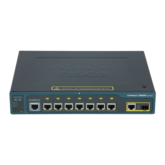
- Page 3 First, you should understand how to turn on your Cisco device, what interfaces it has, and the meanings of the various LEDs (light-emitting diodes) on the chassis. The next few sections cover this in more depth for the 2960.
- Page 4 Chapter 12: Initial Switch Configuration TABLE 12-2 Color Description 2960 SYSTEM SYSTEM Green The system is up and operational. and RPS LEDs Amber The system experienced a malfunction. The system is powered down. Green The RPS is attached and operational. Amber The RPS is installed but is not operational.
- Page 5 Switch Startup TABLE 12-3 LED Color LED Meaning Status Mode and Green A powered-up physical layer connection to the device is attached to the port. Port LEDs Flashing green Traffic is entering and/or leaving the port. Flashing green and amber An operational problem is occurring with the port—perhaps excessive errors or a connection problem.
- Page 6 Chapter 12: Initial Switch Configuration Switch Bootup Process For your initial access to the switch, make sure you plug the rollover cable into the switch’s console port and the other end into the COM port of your computer. Start up a terminal emulation program such as HyperTerminal, Tera Term, or PuTTY to view the command-line interface (CLI) output of the switch.
- Page 7 170 West Tasman Drive San Jose, California 95134-1706 Cisco IOS Software, C2960 Software (C2960-LANBASEK9-M), Version 12.2(40)SE, RELEASE SOFTWARE (fc3) Copyright (c) 1986-2007 by Cisco Systems, Inc. Compiled Fri 24-Aug-07 01:55 by myl Image text-base: 0x00003000, data-base: 0x00FC0000 Initializing flashfs... flashfs[1]: 602 files, 19 directories...
- Page 8 Chapter 12: Initial Switch Configuration This product contains cryptographic features and is subject to United States and local country laws governing import, export, transfer and use. Delivery of Cisco cryptographic cisco WS-C2950-24TT-L (PowerPC405) processor (revision D0) with 61440K/4088K bytes of memory.
- Page 9 The enable secret is a password used to protect access to privileged EXEC and configuration modes. This password, after entered, becomes encrypted in the configuration. Enter enable secret: cisco The enable password is used when you do not specify an enable secret password, with some older software versions, and some boot images.
- Page 10 Chapter 12: Initial Switch Configuration Interface IP-Address OK? Method Status Protocol Vlan1 unassigned YES unset down FastEthernet0/1 unassigned YES unset down down FastEthernet0/2 unassigned YES unset down down FastEthernet0/24 unassigned YES unset down down GigabitEthernet0/1 unassigned YES unset down down GigabitEthernet0/2 unassigned YES unset...
- Page 11 Basic Switch Configuration 12.01. The CD contains a multimedia demonstration of the bootup process of a 2950 switch. ON THE CD CertCam At the end of the script, type 2 to accept and activate your changes, as well as save the configuration to NVRAM. Entering 0 aborts the script and 1 starts the script over, remembering what you just entered, as the defaults, for the questions you were just asked.
- Page 12 Chapter 12: Initial Switch Configuration addressing information on the switch: an IP address associated with an interface and a default gateway address. Here’s the configuration you’ll use: Switch(config)# interface vlan VLAN_# Switch(config-vlan)# ip address IP_address subnet_mask Switch(config-vlan)# exit Switch(config)# ip default-gateway router’s_IP_address With layer 2 switches such as the 2960, you must go into the VLAN interface with which you want the IP address to be associated—this will be the management VLAN in which your administrative PC is located.
- Page 13 Basic Switch Configuration PC-A FIGURE 12-2 10.0.1.10/24 0000.1111.AAAA Simple switch configuration example PC-B 10.0.1.11/24 0000.1111.CCCC Switch-A 10.0.1.2/24 Router-A FA0/0: 10.0.1.1/24 0000.1111.BBBB Switch-A(config-line)# login Switch-A(config-line)# exit Switch-A(config)# enable secret secretpass123 Switch-A(config)# service password-encryption Switch-A(config)# banner motd $ This is a private system and only authorized individuals are allowed! All others will be prosecuted to the fullest extent of the law! Switch-A(config)# interface vlan 1...
- Page 14 Chapter 12: Initial Switch Configuration EXERCISE 12-1 ON THE CD ON THE CD Configuring the Switches In this exercise, you will create a basic configuration on the 2950 switches using Boson’s NetSim simulator on the CD-ROM switch. If you have closed the simulator since the last lab, the simulator will automatically load Chapter 11’s completed configuration.
- Page 15 Basic Switch Configuration Now configure the 2950-2 switch. The commands are the same, except use the appropriate configuration information: the IP address is 192.168.1.3/24. Test connectivity to the Host-1 PC and 2950-1 switch. 1. Click the eSwitches icon in the toolbar and choose 2950-2. 2.
-
Page 16: Mac Address Table
Chapter 12: Initial Switch Configuration CERTIFICATION OBJECTIVE 12.04 Basic Switch Operation and Verification This section focuses on the basic operations of a switch, such as learning MAC addresses and basic verification commands. MAC Address Table You’ll recall that one of the three main functions of a switch is to learn which devices—that is, MAC addresses—are associated with which interfaces or ports. - Page 17 Basic Switch Operation and Verification Be familiar with the output not in the table (unknown), the switch will of the show mac-address-table flood it. command. If a destination MAC address is Static MAC Addresses In addition to having the switches learn MAC addresses dynamically, you can manually create static entries.
- Page 18 Chapter 12: Initial Switch Configuration EXERCISE 12-2 ON THE CD ON THE CD CAM Tables The following sections deal with the CAM table and port security. This exercise will help you become more familiar with the CAM table on a 2950 switch. You’ll perform this lab using Boson’s NetSim simulator.
- Page 19 Host-2. Enter ipconfig /all and compare the MAC address of the PC to that learned by the 2950-1 switch on fastethernet0/4. You should be more comfortable with the CAM table on Cisco switches. CERTIFICATION OBJECTIVE 12.05 Port Security Feature...
- Page 20 Chapter 12: Initial Switch Configuration switch(config-if)# switchport port-security switch(config-if)# switchport port-security maximum value switch(config-if)# switchport port-security violation protect|restrict|shutdown switch(config-if)# switchport port-security mac-address MAC_address switch(config-if)# switchport port-security mac-address sticky Be familiar with configuring limiting the MAC addresses, violation mode, port security with the switchport and sticky learning).
- Page 21 Port Security Feature When an interface is disabled because of a violation with port security, you can reset the interface with this Configuration mode command: errdisable recovery cause psecure-violation. The last two commands in the preceding code listing affect how the switch learns the secure MAC addresses on the interface.
- Page 22 Chapter 12: Initial Switch Configuration Configured MAC Addresses : 1 Aging time : 0 mins Aging type : Absolute SecureStatic address aging : Disabled Security Violation count : 0 In this example, you can see that port security is enabled, the violation mode is restrict, the maximum number of MAC addresses that can be connected to the port is 1, and one MAC address has to be statically configured for the port.
- Page 23 Port Security Feature In this example, three MAC addresses are off of FA0/1, where the first two were learned dynamically and the last one was statically configured. 12.03. The CD contains a multimedia demonstration of configuring and ON THE CD CertCam verifying port security on a switch.
- Page 24 Chapter 12: Initial Switch Configuration CERTIFICATION SUMMARY This chapter focused on basic configuration tasks specific to Cisco Catalyst switches. The 2960 switches were introduced, including the meaning of their LEDs and the use of the MODE button. When a switch boots up, it runs POST, loads the IOS, and then loads its configuration.
- Page 25 Two-Minute Drill ✓ TWO-MINUTE DRILL 2960 Overview ❑ The 2960 switches support Fast Ethernet and/or Gigabit Ethernet interfaces. ❑ The SYSTEM LED will be amber if the switch experiences a malfunction. ❑ The MODE button is used to change the meanings of the port LEDs. ❑...
- Page 26 Chapter 12: Initial Switch Configuration ❑ The defaults for port security are learning one MAC address on the interface with a violation mode of shutdown. ❑ Sticky learning allows a switch to dynamically learn which MAC addresses are associated with an interface, as well as saving these in the running configuration of the switch.
-
Page 27: Self Test
Self Test SELF TEST The following Self Test questions will help you measure your understanding of the material presented in this chapter. Read all the choices carefully, as there may be more than one correct answer. Choose all correct answers for each question. 2960 Overview 1. - Page 28 Chapter 12: Initial Switch Configuration Basic Switch Operation and Verification 6. Enter the switch command that allows you to see the contents of the port address table: __________. 7. Examine the following MAC address table on a switch. What will happen if a switch sees a frame with a destination MAC address of 0000.1111.DDDD? Switch>...
- Page 29 A. Enabling the interfaces is not asked for during the System Configuration Dialog script: 3. ® ✓ interfaces are enabled by default on Cisco switches. ® ˚ B, C, and D are asked for and are thus incorrect answers. Basic Switch Configuration 4.
- Page 30 Chapter 12: Initial Switch Configuration Port Security Feature 8. ® A. Port security is used to prevent unauthorized access to a LAN. ✓ ® ˚ B is incorrect because 802.1Q is a VLAN trunking protocol. C and D are used to restrict access to the switch, not to the LAN for which the switch provides connectivity.