Table of Contents
Advertisement
Advertisement
Table of Contents

Related Manuals for Cisco WS-C1924-A - Catalyst 1900 24 Ports 10MB Switch


Summary of Contents for Cisco WS-C1924-A - Catalyst 1900 24 Ports 10MB Switch
- Page 1 Cisco 1900 Series Integrated Services Router Hardware Installation Americas Headquarters Cisco Systems, Inc. 170 West Tasman Drive San Jose, CA 95134-1706 http://www.cisco.com Tel: 408 526-4000 800 553-NETS (6387) Fax: 408 527-0883 Text Part Number: OL-19084-03...
- Page 2 Modifications to this product not authorized by Cisco could void the FCC approval and negate your authority to operate the product. The Cisco implementation of TCP header compression is an adaptation of a program developed by the University of California, Berkeley (UCB) as part of UCB’s public domain version of the UNIX operating system.
-
Page 3: Table Of Contents
Real-Time Clock 1-12 Chassis Security 1-12 Wireless LAN Connectivity 1-12 Baud Reset Button 1-13 Interface Numbering 1-13 Specifications 1-14 Regulatory Compliance 1-18 Preparing for Router Installation C H A P T E R Safety Recommendations Cisco 1900 Series Hardware Installation... - Page 4 Inspecting the Router Installation Checklist Site Log Required Tools and Equipment for Installation and Maintenance Cable Information and Specifications for Cisco 1900 Series Routers C H A P T E R Console and Auxiliary Port Considerations About Console and Auxiliary Ports...
- Page 5 Installing the Cisco Microsoft Windows 2000 USB Driver 4-17 Installing the Cisco Microsoft Windows Vista USB Driver 4-18 Uninstalling the Cisco USB Driver 4-18 Uninstalling the Cisco Microsoft Windows XP and 2000 USB Driver 4-18 Using the Add Remove Programs Utility 4-18 Using the Setup.exe Program 4-19...
- Page 6 Contents Using the Cisco CLI—Manual Configuration Initial CLI Configuration Configuring the Router Hostname Configuring the Enable and Enable Secret Passwords Configuring the Console Idle Privileged EXEC Timeout 5-10 Configuring Gigabit Ethernet Interfaces 5-12 Specifying a Default Route or Gateway of Last Resort...
- Page 7 Objectives This guide provides an overview and explains how to install, connect, and perform initial configuration for the Cisco 1900 series Integrated Services Routers (ISRs). Some information may not apply to your particular router model. For warranty, service, and support information, see the “Cisco Warranty Terms” section in the Readme First for the Cisco 1900 Series Integrated Services Routers document that was shipped with your router.
- Page 8 Preface Organization This guide includes the following sections: Section Title Description Overview of Cisco 1900 Series Routers Describes the features and specifications of the router. Preparing for Router Installation Describes the site requirements and equipment needed to install the router.
- Page 9 Tämä varoitusmerkki merkitsee vaaraa. Tilanne voi aiheuttaa ruumiillisia vammoja. Ennen kuin käsittelet laitteistoa, huomioi sähköpiirien käsittelemiseen liittyvät riskit ja tutustu onnettomuuksien yleisiin ehkäisytapoihin. Turvallisuusvaroitusten käännökset löytyvät laitteen mukana toimitettujen käännettyjen turvallisuusvaroitusten joukosta varoitusten lopussa näkyvien lausuntonumeroiden avulla. SÄILYTÄ NÄMÄ OHJEET Cisco 1900 Series Hardware Installation OL-19084-02...
- Page 10 Utilize o número da instrução fornecido ao final de cada aviso para localizar sua tradução nos avisos de segurança traduzidos que acompanham este dispositivo. GUARDE ESTAS INSTRUÇÕES Cisco 1900 Series Hardware Installation OL-19084-02...
- Page 11 Använd det nummer som finns i slutet av varje varning för att hitta dess översättning i de översatta säkerhetsvarningar som medföljer denna anordning. SPARA DESSA ANVISNINGAR Cisco 1900 Series Hardware Installation OL-19084-02...
- Page 12 Brug erklæringsnummeret efter hver advarsel for at finde oversættelsen i de oversatte advarsler, der fulgte med denne enhed. GEM DISSE ANVISNINGER Cisco 1900 Series Hardware Installation OL-19084-02...
- Page 13 Preface Cisco 1900 Series Hardware Installation xiii OL-19084-02...
- Page 14 Appliance and Material Safety Law prohibits the use of UL-certified cables (that have the “UL” shown on the code) for any other electrical devices than products designated by CISCO. The use of cables that are certified by Electrical Appliance and Material Safety Law (that have “PSE” shown on the code) is not limited to CISCO-designated products.
-
Page 15: Related Documentation
Statement 1038 Related Documentation The Cisco IOS software that runs your Cisco 1940 series router includes extensive features and functionality. For information that is beyond the scope of this document, or for additional information, use the following resources. -
Page 16: Obtaining Documentation And Submitting A Service Request
Obtaining Documentation and Submitting a Service Request For information on obtaining documentation, submitting a service request, and gathering additional information, see the monthly What’s New in Cisco Product Documentation, which also lists all new and revised Cisco technical documentation, at: http://www.cisco.com/en/US/docs/general/whatsnew/whatsnew.html... -
Page 17: Safety Warnings
Universal serial bus (USB) ports are available for USB devices, and a USB mini Type-B serial console port is available in addition to the RJ-45 console connector. This chapter provides an overview of the Cisco 1900 series routers and includes the following sections: Safety Warnings, page 1-1 •... -
Page 18: Chapter 1 Overview Of The Router
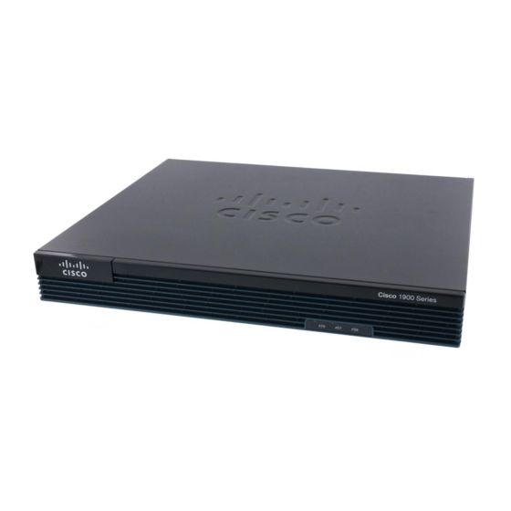
LEDs of the Cisco 1941 router. Figure 1-5 shows the back panel connectors on the Cisco 1941 router. Power off the router and the power over Ethernet (PoE) before installing an EHWIC in the Cisco 1905 Caution and Cisco 1921 ISRs. Figure 1-1shows the front panel of the Cisco 1905 and Cisco 1921 router and LED names. - Page 19 Module Support on Cisco’s Integrated Services Routers Generation 2 http://cisco.com/en/US/prod/collateral/routers/ps10538/aag_c07_563807.pdf for supported modules. 6. Power off the PoE before installing an EHWIC in the Cisco 1905 and Cisco 1921 ISRs. Figure 1-3 shows the front panel of a Cisco 1941 wireless router with antennas mounted.
- Page 20 1. The antenna mounts are not available on the non-wireless models. 2. Some LEDs are not available on the non-wireless models. Figure 1-4 shows the front panel of the Cisco 1941W (without antennas) with the LED names. Figure 1-4 Cisco 1941 and Cisco 1941W Router LEDs...
-
Page 21: Hardware Features
Chapter 1 Overview of the Router Hardware Features Figure 1-5 Back Panel of the Cisco 1941 and Cisco 1941W Router Cisco 1900 Series EHWIC 1 EHWIC 0 GE 0/1 DO NOT REMOVE DURING CF 1 DO NOT REMOVE DURING CF 0... -
Page 22: Product Serial Number Location
Cisco 1905 and Cisco 1921 series routers is located on the bottom of the chassis. (See Figure 1-8.) The serial number label for the Cisco 1940 series routers is located on the rear of the chassis on a pull-out tab. (See Figure 1-8.) -
Page 23: Cisco Product Identification Tool
Cisco Product Identification Tool The Cisco Product Identification (CPI) tool provides detailed illustrations and descriptions showing where to locate serial number labels on Cisco products. It includes the following features: A search option that allows browsing for models using a tree-structured product hierarchy •... -
Page 24: Removable, Interchangeable, And Optional Modules
Cisco 1940 series ISRs feature an optional upgrade to the internal power supply providing in-line power (802.3af-compliant Power-over-Ethernet (PoE) and Cisco standard inline power) to optional integrated switch modules. The Cisco 1905, and Cisco 1921 have an external feed for PoE. (See Figure 1-2.) -
Page 25: Memory
RAM represent the minimum usable memory. You can install additional RAM in multiples of the default amount, up to the maximum amount on the Cisco 1940 series ISRs. The Cisco 1905 and Cisco 1921 have factory installed, fixed memory modules and no expansion slots. -
Page 26: Led Indicators
Table 1-4 summarizes the LED indicators that are located in the router bezel or chassis, but not on the interface cards. Not all models have every LED. Table 1-4 Summary of Cisco 1900 Series LED Indicators Color Description Location Solid Solid green indicates normal operation. - Page 27 Chapter 1 Overview of the Router Hardware Features Table 1-4 Summary of Cisco 1900 Series LED Indicators (continued) Color Description Location WLAN Green Autonomous Mode Front panel On—Wireless link is up. Blinking—Ethernet link is up and data is either being received or being transmitted.
-
Page 28: Chassis Ventilation
Cisco 1900 series router has a lithium battery. This battery lasts the life of the router under the operating environmental conditions specified for the router, and is not field-replaceable. If the lithium battery in a Cisco 1900 ISR should fail, the router must be returned to Cisco for repair. Note Although the battery is not intended to be field-replaceable, the following warning must be heeded: Dispose of used batteries according to the manufacturer’s instructions. -
Page 29: Baud Reset Button
Baud Reset Button The Cisco 1905 and Cisco 1921 ISRs have a baud reset button on the back panel. When the button is pressed during power on, ROMMON resets the router to the default console port configuration. If the baud reset button is pressed for longer than 30 seconds, the router defaults to the read-only ROMMON image. -
Page 30: Specifications
EHWIC/WIC/VWIC 0/1/0 to 0/1/0 (single or double-wide) On the Cisco 1900 series router, the numbering format for configuring an async interface is 0/slot/port. To Note configure the line associated with an async interface, simply use the interface number to specify the async line. - Page 31 Chapter 1 Overview of the Router Specifications Table 1-7 Cisco 1905 and 1921 Series Router Specifications Description Specification Surge current <50 A • Ports Console One RJ-45 connector and one USB mini Type B, USB 2.0 compliant. Baud rates: 1200, 2400, 4800, 9600, 19200, 38400, 57600, and 115200.
- Page 32 Regulatory Compliance and Safety Information for Cisco 1900 Series Routers. 1. Refer to the Cisco 1900 Series Integrated Services Routers Data Sheet for additional information. 2. Rack unit (RU 3. 480 Mb/s individually, bandwidth is shared when both are used.
- Page 33 AS/NZS 3548 Class A VCCI V-3 CNS 13438 EN 300-386 EN 61000 (Immunity) EN 55024, CISPR 24 EN50082-1 For detailed compliance information, see Regulatory Compliance and Safety Information for Cisco 1900 Series Routers. Cisco 1900 Series Hardware Installation 1-17 OL-19084-02...
-
Page 34: Regulatory Compliance
Regulatory Compliance and Safety Information for Cisco 1900 Series Routers. 1. Refer to the Cisco 1900 Series Integrated Services Routers Data Sheet for additional information. 2. Rack unit (RU 3. 480 Mb/s individually, bandwidth is shared when both are used. -
Page 35: General Guidelines
C H A P T E R Preparing for Router Installation This chapter describes the site requirements and equipment needed to install your Cisco 1900 series integrated services router. Safety Recommendations, page 2-1 • General Site Requirements, page 2-3 •... -
Page 36: C H A P T E R 2 Preparing For Router Installation
Do not work alone if hazardous conditions exist. • • Never assume that power is disconnected from a circuit. Always check. • Never open the enclosure of the router’s internal power supply. Cisco 1900 Series Hardware Installation OL-19084-02... -
Page 37: Preventing Electrostatic Discharge Damage
Power Supply Considerations, page 2-4 • Site Environment, page 2-4 • Site Configuration, page 2-4 • Wireless LAN Considerations, page 2-5 • Cisco 1900 Series Hardware Installation OL-19084-02... -
Page 38: Power Supply Considerations
Site Environment The Cisco 1900 series router is designed for placement on a desktop, rack-mounted or wall mounted. The location of your router is an extremely important consideration for proper operation. Equipment placed too close together, inadequate ventilation, and inaccessible panels can cause malfunctions and shutdowns, and can also make maintenance difficult. -
Page 39: Wireless Lan Considerations
The type of antenna used with your wireless router and its location greatly impact the quality of wireless connections to the router. Cisco 1900 series wireless routers are compatible with three different antenna types—swivel-mount dipole antennas that mounts on the back panel of the router, a wall-mount antenna, and a ceiling-mount antenna. -
Page 40: Site Log
Installation Checklist for Site_____________________________________________ Router Name_______________________________________________________ Task Verified by Date Router quick start guide received Cisco Regulatory Compliance and Safety Information Roadmap document received Product registration card received Chassis components verified Initial electrical connections established ASCII terminal (for local configuration) or... -
Page 41: Required Tools And Equipment For Installation And Maintenance
Cables for connection to WAN and LAN ports (dependent on configuration) • For more information on cable specifications, refer to Cisco Modular Access Router Cable Note Specifications. Ethernet hub or PC with a network interface card for connection to Ethernet (LAN) ports •... - Page 42 Chapter 2 Preparing for Router Installation Required Tools and Equipment for Installation and Maintenance Cisco 1900 Series Hardware Installation OL-19084-02...
-
Page 43: Console And Auxiliary Port Considerations
Cable Information and Specifications for Cisco 1900 Series Routers This document gives cable information and specifications for the console port, auxiliary port, and network ports on your Cisco 1900 series integrated services router. • Console and Auxiliary Port Considerations, page 3-1 Preparing to Connect to a Network, page 3-3 •... -
Page 44: C H A P T E R 3 Cable Information And Specifications For Cisco 1900 Series Routers
“Connecting to the Console Port with Microsoft Windows” section on page 4-14. For operation with Microsoft Windows, the Cisco Windows USB Console Driver must be installed on any PC connected to the Console port. If it is not installed, prompts guide you through a simple installation process. -
Page 45: Auxiliary Port Connections
Cisco Modular Access Router Cable Specifications for more information about network connections and interfaces. Ethernet Connections The IEEE has established Ethernet as standard IEEE 802.3. The Cisco 1941 Ethernet implementations are as follows: 1000BASE-T—1000 Mb/s full-duplex transmission over a Category 5 or better unshielded •... -
Page 46: About Serial Connections
The synchronous serial ports available for the router support the following signaling standards: EIA/TIA-232, EIA/TIA-449, V.35, X.21, and EIA-530. You can order a Cisco DB-60 shielded serial transition cable that has the appropriate connector for the standard you specify. The documentation for the device that you want to connect should indicate the standard used for that device. -
Page 47: Transmission Speeds And Distance Limitations
Chapter 3 Cable Information and Specifications for Cisco 1900 Series Routers Preparing to Connect to a Network the shielded serial transition cable has a DB-60 connector, which connects to the DB-60 port on a serial WIC. The other end of the serial transition cable is available with a connector appropriate for the standard that you specify. -
Page 48: Isdn Bri Connections
Chapter 3 Cable Information and Specifications for Cisco 1900 Series Routers Preparing to Connect to a Network Synchronous interface—Maximum baud rate is 128 kbps, full-duplex. • ISDN BRI Connections The BRI WICs provide Integrated Services Digital Network (ISDN) Basic Rate Interface (BRI) connections. -
Page 49: About Modules
C H A P T E R Installing and Connecting the Router Cisco 1900 series routers are normally shipped with a complement of components that can be upgraded or replaced to expand and enhance the router’s functionality. These components either are inserted internally into the router or are plugged into slots in the router chassis. -
Page 50: Plug-In Modules
Safety Warnings If you need to remove or upgrade either of these items, follow the procedures given in Installing and Upgrading Internal Modules and FRUs in Cisco 1900 Series ISRs. Plug-In Modules The following components plug into the router chassis: •... -
Page 51: C H A P T E R 4 Installing And Connecting The Router
Setting Up the Chassis The Cisco 1900 series router can be installed on a desktop, and can also be mounted on a wall. Select the setup that best meets the needs of your network. These setups are described in the following sections: Chassis Airflow Diagram, page 4-3 •... -
Page 52: Setting The Chassis On A Desktop
NE TW OR Setting the Chassis on a Desktop You can place Cisco 1900 series routers on a desktop or shelf. The Cisco 1900 series router is shipped with the rubber feet attached to the chassis to protect the desktop. - Page 53 Installing and Connecting the Router Setting Up the Chassis The Cisco 1900 series router can be wall-mounted by using two number six, 3/4-inch screws and the mounting features on the bottom of the router. You must provide the screws. We recommend using pan-head or round-head screws.
- Page 54 Chapter 4 Installing and Connecting the Router Setting Up the Chassis Figure 4-4 shows the wall-mounting features on the Cisco 1941 series routers. Figure 4-4 Wall-Mounting Features on the Cisco 1941 Router Wall screws 5 inches (12.7 cm) Chassis mounting holes (on bottom)
-
Page 55: Rack-Mounting The Chassis
Failure to stabilize the rack can cause the rack to tip over. Statement 1048 The Cisco 1900 series router can be installed in a 19-inch EIA rack. Mounting brackets allow installing in either a front and rear facing position. - Page 56 Chapter 4 Installing and Connecting the Router Setting Up the Chassis Figure 4-5 Bracket Installation for Front Mounting the Cisco 1905 and Cisco 1921 ISRs Ci sc o 29 00 Se rie SY S AC T PO E Figure 4-6 shows how to attach the brackets to the sides of the router with the back panel forward.
-
Page 57: Installing The Chassis Ground Connection
Figure 4-8 shows how to attach the brackets to the sides of the router with the back panel forward. Figure 4-8 Bracket Installation for Back Mounting the Cisco 1940 Series ISR DO NO T RE MO VE NE TW OR... - Page 58 Chapter 4 Installing and Connecting the Router Installing the Chassis Ground Connection To install the ground connection for a Cisco 1900 series router, follow these steps. Procedure Step 1 Strip one end of the ground wire to expose approximately 0.75 in. (20 mm) of conductor.
-
Page 59: Connecting Wan And Lan Cables
Ports and Cabling, page 4-13 • Connection Procedures and Precautions, page 4-14 • You can order additional network connection cables and transceivers from Cisco. For ordering Note information, contact Cisco customer service. For cable pinouts, refer to Cisco Modular Access Router Cable Specifications. - Page 60 RJ-11 (phone) port wires (conductors), the conductors of a cable connected to the RJ-11 port, or the associated circuit-board when the ringer is active. The ringer is activated by an incoming call. Statement 1042 Cisco 1900 Series Hardware Installation 4-12 OL-19084-02...
-
Page 61: Ports And Cabling
Installing and Connecting the Router Connecting WAN and LAN Cables Ports and Cabling Table 4-1 summarizes some typical WAN and LAN connections for Cisco 1900 series routers. These connections are also described in detail in Cisco Modular Access Router Cable Specifications. -
Page 62: Connection Procedures And Precautions
The software should be configured with the following parameters: 9600 baud, 8 data bits, no parity, 1 stop bit, and no flow control. Refer to the Cisco 3900 Series, 2900 Series, and 1900 Series Software Configuration Guide for detailed information about using Cisco IOS software for configuring the router. - Page 63 Windows based PC, you must install the Windows USB driver. See the “Installing the Cisco Microsoft Windows USB Device Driver” section on page 4-17. You must use either the USB port or the RJ-45 port, but not both simultaneously. See the “USB...
-
Page 64: Connecting To The Console Port With Mac Os X
1 root root 188, 0 Jan 14 18:02 ttyACM0 root@usb-suse /dev# Connect to the USB port with the following command followed by the router USB port speed: Step 4 root@usb-suse /dev# screen /dev/ttyACM0 9600 Cisco 1900 Series Hardware Installation 4-16 OL-19084-02... -
Page 65: Installing The Cisco Microsoft Windows Usb Device Driver
The USB console is ready for use. Installing the Cisco Microsoft Windows 2000 USB Driver Procedure Step 1 Obtain the file cisco_usbconsole.zip from the Cisco.com web site and unzip it. Double-click the file setup.exe. Step 2 The Cisco Virtual Com InstallShield Wizard begins. Click Next. -
Page 66: Installing The Cisco Microsoft Windows Vista Usb Driver
Wizard windows appear. The USB console is ready for use. Installing the Cisco Microsoft Windows Vista USB Driver Procedure Obtain the file cisco_usbconsole.zip from the Cisco.com web site and unzip it. Step 1 Double-click the file setup.exe. Step 2 The Cisco Virtual Com InstallShield Wizard begins. Click Next. -
Page 67: Using The Setup.exe Program
Disconnect the router console terminal before uninstalling the driver. Procedure Run the setup.exe program. Click Next. Step 1 The InstallShield Wizard for Cisco Virtual Com appears. Click Next. Step 2 When the Program Maintenance window appears, select the Remove radio button. Click Next. Step 3 When the Remove the Program window appears, click Remove. -
Page 68: Connecting To The Auxiliary Port
Make sure that your modem and the router auxiliary port are configured for the same transmission speed Step 4 (up to 115200 bps is supported) and for mode control with data carrier detect (DCD) and data terminal ready (DTR) operations. Cisco 1900 Series Hardware Installation 4-20 OL-19084-02... -
Page 69: Connecting Power
Chapter 4 Installing and Connecting the Router Connecting Power Connecting Power This section explains how to connect AC or DC power to Cisco 1900 series routers. It covers the following topics: Connecting to AC Power, page 4-21 • Connecting to DC Power, page 4-22 •... -
Page 70: Connecting To Dc Power
Warning Use copper conductors only. Statement 1025 DC Wiring Requirements for Cisco 1900 Series Routers A Cisco 1921 router with a DC-input power supply requires copper wire and crimp-type terminals for the power connections. Table 4-2 summarizes the wiring requirements. -
Page 71: Cisco 1900 Series Router Wiring Procedure For Dc Input
Chapter 4 Installing and Connecting the Router Connecting Power Cisco 1900 Series Router Wiring Procedure for DC Input To connect a router to a DC power source, perform the following steps. Procedure Remove power from the DC circuit. To ensure that power is removed from the DC circuit, locate the... - Page 72 DC-input power source wire extends from the terminal block plug. Statement 122 Caution Dual sources with opposite-polarity grounding damage equipment. Step 5 Reinstall the plastic safety cover over the terminal. See Figure 4-15 Figure 4-16. Cisco 1900 Series Hardware Installation 4-24 OL-19084-02...
- Page 73 Statement 117 Step 6 Turn on power to the DC circuit. Be sure to remove the tape that was used to secure the circuit-breaker switch in the OFF position. Cisco 1900 Series Hardware Installation 4-25 OL-19084-02...
- Page 74 Chapter 4 Installing and Connecting the Router Connecting Power Cisco 1900 Series Hardware Installation 4-26 OL-19084-02...
-
Page 75: Powering Up The Router
You have connected the power and interface cables. • You have properly seated the external Compact Flash memory card into its slot. For installation • instructions, see Installing and Upgrading Internal Modules and FRUs in Cisco 1900 Series ISRs. Cisco 1900 Series Hardware Installation OL-19084-02... -
Page 76: Powering Up The Cisco Router
You have determined the IP addresses for the Ethernet and serial interfaces. Powering Up the Cisco Router To power up your Cisco router, follow this procedure to verify the router has performed the initialization and self-test. When the procedure is finished, the router is ready to configure. -
Page 77: Chapter 5 Configuring The Router
(GUI). Using the Cisco Setup Command Facility Cisco Setup Command Facility lets you configure the initial router settings through a configuration dialog. If you see the following messages, the router has booted and is ready for initial configuration using the setup command facility. - Page 78 Configuring the Router Performing the Initial Configuration on the Router Procedure Step 1 Enter the setup command facility. From the Cisco IOS CLI, enter the setup command in privileged EXEC mode, enter the following: Router> enable Password: <password> Router# setup...
- Page 79 Class A network is 10.0.0.0, 24 subnet bits; mask is /24 The system creates the following configuration command script: hostname myrouter enable secret 5 $1$t/Dj$yAeGKviLLZNOBX0b9eifO0 enable password cisco123 line vty 0 4 password cisco snmp-server community public ! no ip routing interface GigabitEthernet0/0 shutdown...
-
Page 80: Using Cisco Configuration Professional Express
Password: password Router# configure terminal Router(config)# Using Cisco Configuration Professional Express Use the Cisco Configuration Professional Express web-based application to configure the initial router settings. See Cisco Configuration Professional Express User Guide for detailed instructions. For help with interface and port numbering, see the “Interface Numbering”... -
Page 81: Initial Cli Configuration
Performing the Initial Configuration on the Router If the system configuration dialog message does not appear, a default configuration file was installed on the router prior to shipping. See the “Using Cisco Configuration Professional Express” section on page 5-6 to configure the router. -
Page 82: Configuring The Router Hostname
Enter your password if prompted. • Example: Router> enable Step 2 Enters global configuration mode. configure terminal Example: Router# configure terminal Step 3 Specifies or modifies the hostname for the network server. hostname name Example: Router(config)# hostname myrouter Cisco 1900 Series Hardware Installation OL-19084-02... -
Page 83: Configuring The Enable And Enable Secret Passwords
We recommend that you use the enable secret command because it uses an improved encryption algorithm. Use the enable password command only if you boot an older image of the Cisco IOS software or if you boot older boot ROMs that do not recognize the enable secret command. -
Page 84: Configuring The Console Idle Privileged Exec Timeout
When you configure the console line, you can also set communication parameters, specify autobaud connections, and configure terminal operating parameters for the terminal that you are using. For more information on configuring the console line, see the Cisco IOS Configuration Fundamentals and Network Management Configuration Guide. In particular, see the “Configuring Operating Characteristics for Terminals”... - Page 85 Verify that you properly configured the idle privileged • EXEC timeout. Example: Router(config)# show running-config Examples The following example shows how to set the console idle privileged EXEC timeout to 2 minutes 30 seconds: Cisco 1900 Series Hardware Installation 5-11 OL-19084-02...
-
Page 86: Configuring Gigabit Ethernet Interfaces
For comprehensive configuration information on Gigabit Ethernet interfaces, see the “Configuring LAN Interfaces” chapter of the Cisco IOS Interface and Hardware Component Configuration Guide. For information on interface numbering, see the software configuration guide for your router. SUMMARY STEPS... - Page 87 Sample Output for the show ip interface brief Command Router# show ip interface brief Interface IP-Address OK? Method Status Protocol GigabitEthernet0/0 172.16.3.3 YES NVRAM GigabitEthernet0/1 unassigned YES NVRAM administratively down down Router# Cisco 1900 Series Hardware Installation 5-13 OL-19084-02...
-
Page 88: Specifying A Default Route Or Gateway Of Last Resort
The Cisco IOS software uses the gateway (router) of last resort if it does not have a better route for a packet and if the destination is not a connected network. This section describes how to select a network as a default route (a candidate route for computing the gateway of last resort). -
Page 89: Gateway Of Last Resort
In the case of RIP, there is only one choice, network 0.0.0.0. In the case of IGRP, there might be several networks that can be candidates for the system default. The Cisco IOS software uses both administrative distance and metric information to determine the default route (gateway of last resort). - Page 90 Gateway of last resort is 172.28.99.2 to network 192.168.24.0 172.24.0.0 255.255.255.0 is subnetted, 1 subnets 172.24.192.0 is directly connected, FastEthernet0 172.24.0.0 255.255.0.0 [1/0] via 172.28.99.0 192.168.24.0 [1/0] via 172.28.99.2 172.16.0.0 255.255.255.0 is subnetted, 1 subnets 172.16.99.0 is directly connected, FastEthernet1 Router# Cisco 1900 Series Hardware Installation 5-16 OL-19084-02...
-
Page 91: Configuring Virtual Terminal Lines For Remote Console Access
The router has five virtual terminal lines by default. However, you can create additional virtual terminal lines as described in the Cisco IOS Terminal Services Configuration Guide, Release 12.4. See the Configuring Terminal Operating Characteristics for Dial-In Sessions section. -
Page 92: Configuring The Auxiliary Line
After you configure the vty lines, follow these steps: (Optional) To encrypt the virtual terminal line password, see the “Configuring Passwords and • Privileges” chapter in the Cisco IOS Security Configuration Guide. Also see the Cisco IOS Password Encryption Facts tech note. -
Page 93: Verifying Network Connectivity
Prerequisites Complete all previous configuration tasks in this chapter. • The router must be connected to a properly configured network host. • SUMMARY STEPS enable ping [ip-address | hostname] telnet {ip-address | hostname} Cisco 1900 Series Hardware Installation 5-19 OL-19084-02... - Page 94 Extended commands [n]: Sweep range of sizes [n]: Type escape sequence to abort. Sending 5, 100-byte ICMP Echos to 192.168.7.27, timeout is 2 seconds: !!!!! Success rate is 100 percent, round-trip min/avg/max = 1/2/4 ms Cisco 1900 Series Hardware Installation 5-20 OL-19084-02...
-
Page 95: Saving Your Router Configuration
Saving Backup Copies of Configuration and System Image To aid file recovery and minimize downtime in case of file corruption, we recommend that you save backup copies of the startup configuration file and the Cisco IOS software system image file on a server. SUMMARY STEPS... - Page 96 {flash0|flash1}: tftp: privileged EXEC command to copy the system image (c3900-2is-mz) to a TFTP server. The router uses the default username and password. Cisco 1900 Series Hardware Installation 5-22 OL-19084-02...
-
Page 97: Verifying The Initial Configuration
Use the copy running-config startup-config command to save the configuration to NVRAM. Verifying the Initial Configuration To verify the initial configuration on the router, enter the following commands in the Cisco IOS: • show version—Displays the system hardware version; the installed software version; the names and sources of configuration files;... - Page 98 Chapter 5 Configuring the Router Verifying the Initial Configuration Cisco 1900 Series Hardware Installation 5-24 OL-19084-02...
-
Page 99: Getting Software Licenses For The Router
• Additional Information, page 6-3 • Activating a New Software Package or Feature Before You Begin If you do not have a Cisco.com username and password, register for an account at the following URL • https://tools.cisco.com/RPF/register/register.do. Procedure Step 1 Purchase the software package or feature you want to install. You will receive a product activation key (PAK) with your purchase. -
Page 100: Rma License Transfer
Receive License File Option 3 Cisco Call Home Install License RMA License Transfer To transfer a software license from a failed device to a new device, go to the Cisco licensing portal at http://www.cisco.com/go/license. Cisco 1900 Series Hardware Installation OL-19084-02... -
Page 101: C H A P T E R 6 Getting Software Licenses For The Router
You will need the SN and PID of the defective device, as well as the RMA router to initiate an RMA Note replacement license. Additional Information Software Activation on Cisco Integrated Services Routers and Cisco Integrated Service Routers Generation 2 for detailed information about software activation on Cisco ISR G2 platforms. Cisco 1900 Series Hardware Installation... - Page 102 Chapter 6 Getting Software Licenses for the Router Additional Information Cisco 1900 Series Hardware Installation OL-19084-02...