Table of Contents
Advertisement
Advertisement
Table of Contents

Related Manuals for D-Link DWS-3024


Summary of Contents for D-Link DWS-3024
- Page 2 D-Link Unified Access System User Manual FCC Warning This equipment has been tested and found to comply with the limits for a Class A digital device, pursuant to Part 15 of the FCC Rules. These limits are designed to provide reasonable protection against harmful interference when the equipment is operated in a commercial environment.
-
Page 3: Table Of Contents
D-Link Unified Switch ........ - Page 4 Connecting to the Core Network ........4 Installing the D-Link Unified Access System ....53 System Deployment Overview.
- Page 5 Resetting the Access Points ........Managing Radio Frequency Settings ......Configuring Channel Plan and Power Settings .
- Page 6 Default D-Link Unified Switch Settings ......Default D-Link Access Point Settings ......
- Page 7 802.11e and WMM Standards Support ......Coordinating Traffic Flow ........QoS Queues and DSCP on Packets .
- Page 8 D-Link Unified Access System User Manual © 2001- 2008 D-Link Corporation. All Rights Reserved.
-
Page 9: List Of Figures
Figure 10. Inter-Subnet Roaming ................. 38 Figure 11. Front Panel View of the DWS-3024L as Shipped ......40 Figure 12. Front Panel View of the DWS-3024 as Shipped ......... 40 Figure 13. Front Panel View of the DWS-3026 as Shipped ......... 40 Figure 14. - Page 10 Figure 84. CP Activation and Activity Status............. 179 Figure 85. Interface Activation Status ..............181 Figure 86. Interface Capability Status ..............182 Figure 87. Client Summary................. 183 Figure 88. Client Detail ..................184 Figure 89. Client Statistics.................. 185 © 2001- 2008 D-Link Corporation. All Rights Reserved.
- Page 11 List of Figures Figure 90. Interface - Client Status ..............185 Figure 91. CP - Client Status ................186 Figure 92. SNMP Trap Configuration ..............187 Figure 93. Sample WLAN Visualization............190 Figure 94. Multiple Graphs................. 194 Figure 95. List View and Tabbed View.............. 194 Figure 96.
- Page 12 D-Link Unified Access System User Manual © 2001- 2008 D-Link Corporation. All Rights Reserved.
-
Page 13: List Of Tables
List of Tables List of Tables Table 1. Typographical Conventions ........16 Table 2. - Page 14 Table 84. VLAN Priority Tags ........234 © 2001- 2008 D-Link Corporation. All Rights Reserved.
-
Page 15: About This Document
D-Link Unified Access System. Audience The information in this guide is intended for the person responsible for installing, configuring, monitoring, and maintaining the D-Link Unified Access System as part of a network infrastructure. Organization The D-Link Unified Access System User Manual contains the following chapters: •... -
Page 16: Safety Instructions
An object has fallen into the product. The product has been exposed to water. The product has been dropped or damaged. The product does not operate correctly when you follow the operating instructions. © 2001- 2008 D-Link Corporation. All Rights Reserved. - Page 17 About This Document • Keep your system away from radiators and heat sources. Also, do not block the cooling vents. • Do not spill food or liquids on your system components, and never operate the product in a wet environment. If the system gets wet, see the appropriate section in your troubleshooting guide or contact your trained service provider.
-
Page 18: General Precautions For Rack-Mountable Products
Do not attempt to connect power to the system until grounding cables are connected. Completed power and safety ground wiring must be inspected by a qualified electrical inspector. An energy hazard will exist if the safety ground cable is omitted or disconnected. © 2001- 2008 D-Link Corporation. All Rights Reserved. -
Page 19: Protecting Against Electrostatic Discharge
About This Document Protecting Against Electrostatic Discharge Static electricity can harm delicate components inside your system. To prevent static damage, discharge static electricity from your body before you touch any of the electronic components, such as the microprocessor. You can do so by periodically touching an unpainted metal surface on the chassis. - Page 20 D-Link Unified Access System User Manual © 2001- 2008 D-Link Corporation. All Rights Reserved.
-
Page 21: Overview Of The D-Link Unified Access System
Wireless clients can roam among the access points managed by peer Unified Switches without losing network connections. Whether or not you have a peer group, the D-Link Unified Access System can support a total of 8000 wireless clients. D-Link Unified Access System Components... -
Page 22: D-Link Unified Switch
Interface (UI) or command-line interface (CLI). In Managed Mode, the D-Link Access Point is part of the D-Link Unified Access System, and you manage it by using the D-Link Unified Switch. If an AP is in Managed Mode, the Administrator Web UI services on the AP are disabled. -
Page 23: Wlan Visualization
Web browser. WLAN Visualization detects and displays the D-Link Unified Switch, D-Link Access Points, other access points, and all wireless clients associated with the D-Link Access Point. You can import information about your building layout to customize the network view. -
Page 24: Single Unified Switch Deployment
D-Link Unified Access System User Manual Single Unified Switch Deployment When you deploy a D-Link Access Point, the D-Link Unified Switch can automatically detect the AP and assign a default profile, which includes automatic RF channel selection and automatic power adjustment. -
Page 25: Understanding The User Interfaces
1 Overview of the D-Link Unified Access System up to 48 access points (DWS-3024 and DWS-3026) or 24 access points (DWS-3024L). The Unified Switch and the APs it manages do not need to be on the same subnet. Figure 3. Peer Unified Switch with Layer 3 Roaming Support... -
Page 26: Using The Web Interface
Configuration Status and Options Interface Configuration Graphic The interface configuration graphic is a Java™ applet that displays the ports on the D-Link Unified Switch. This graphic appears at the top of each page to provide an alternate way to navigate to configuration and monitoring options. -
Page 27: Figure 5. Cascading Navigation Menu
1 Overview of the D-Link Unified Access System Click the port you want to view or configure to see a menu that displays statistics and configuration options. Click the menu option to access the page that contains the configuration or monitoring options. Click Logout to log out of the Web Interface. From the Logout prompt, click Ok to save your changes and make the changes permanent. -
Page 28: Using The Command-Line Interface
To display the commands available in the current mode, enter a question mark (?) at the command prompt. To display the available command keywords or parameters, enter a question mark (?) after each word you type at the command prompt. If there are no additional command © 2001- 2008 D-Link Corporation. All Rights Reserved. -
Page 29: Using Snmp
Press Enter to execute the command For more information about the CLI, see the D-Link CLI Command Reference. The D-Link CLI Command Reference lists each command available from the CLI by the command name and provides a brief description of the command. Each command reference also contains the following information: •... -
Page 30: Wireless System Features And Standards Support
To access configuration information for SNMPv1 or SNMPv2, click LAN > Administration > SNMP Manager and click the page that contains the information to configure. Wireless System Features and Standards Support In addition to core switching features, the D-Link Unified Switch supports the following features and standards: •... - Page 31 Configuration & Firmware Upload/Download Each AP supports 8 virtual access points (VAPs) per radio. You can configure a unique SSID and security policy on each VAP. The following list shows some of the D-Link Access Point features and standards support: •...
- Page 32 Inhibit / Ignore SSID broadcast Weak IV avoidance MAC Authentication Port/IP blocking RADIUS support PEAP TLS and TTLS WPA (Personal, Enterprise) WPA2 (Personal, Enterprise) 802.11i 802.1X Supplicant Client Authentication Firewall/IP filtering support © 2001- 2008 D-Link Corporation. All Rights Reserved.
-
Page 33: Planning The D-Link Unified Access System Network
Ethernet devices. It is an advanced, scalable, standards-based solution for wireless networking. The D-Link Unified Access System enables wireless local area network (WLAN) deployment while providing state-of-the-art wireless networking features. This chapter contains the following sections to help you plan your D-Link Unified Access System: •... -
Page 34: Wlan Topology Considerations
LAN infrastructure. Since the D-Link Unified Switch has Layer 2/3 switching functions as well as WLAN data and management functions, you can connect D-Link Access Points, wired PCs, or other network... -
Page 35: Figure 8. Wiring Closet Topology
8, the D-Link Unified Switches are both LAN and WLAN switches that handle traffic from end users connected to the wired LAN as well as traffic from the D-Link Access Points. In the diagram, Building 1 and Building 2 have a D-Link Unified Switch on each floor. -
Page 36: Access Point-To-Switch Discovery
61. Access Point Placement D-Link Access Points can be on the same subnet as the switch or on a different subnet. You can connect the AP directly to the Unified Switch or to another networking device. The range... -
Page 37: Network Planning To Support Layer 3 Roaming
2 Planning the D-Link Unified Access System Network of the D-Link Access Point is about 100 meters, but the range is affected by various environmental factors. To maximize the range, use the following guidelines for the placement of the AP: •... -
Page 38: Figure 10. Inter-Subnet Roaming
D-Link Unified Access System User Manual The D-Link Unified Access System provides two ways to prevent the IP address of a roaming client from changing: 1. You can associate the SSID for roaming with a VLAN and configure the network devices on your network to allow VLAN trunking across different subnets. -
Page 39: Installing The Hardware
Installing the Hardware This chapter provides instructions for installing the D-Link DWS-3024, DWS-3024L, and DWS-3026 switch hardware. The following sections describe this installation process: • Hardware Overview Front Panel Components LED Indicators Rear Panel Description Side Panels • Installation Package Contents... -
Page 40: Front Panel Components
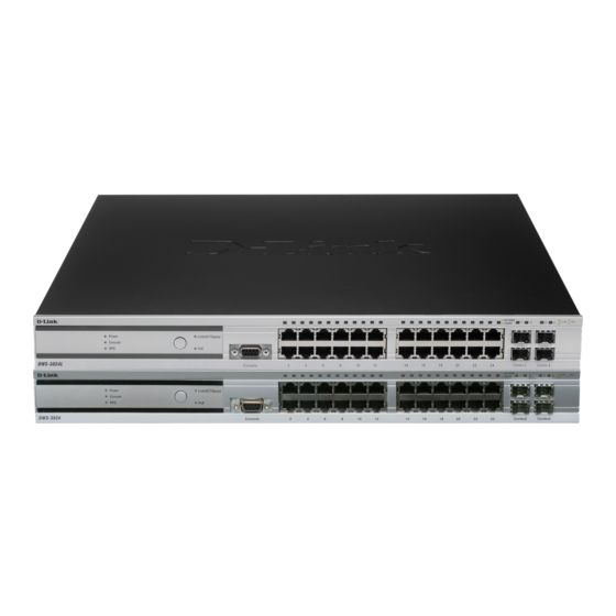
LED indicators in more detail. Figure 11. Front Panel View of the DWS-3024L as Shipped Figure 12. Front Panel View of the DWS-3024 as Shipped Figure 13. Front Panel View of the DWS-3026 as Shipped © 2001- 2008 D-Link Corporation. All Rights Reserved. -
Page 41: Led Indicators
The Switch supports LED indicators for Power, Console, RPS, PoE, and Port LEDs including 10GE port LEDs for optional module inserts on the DWS-3026. Figure 14. LED Indicators on DWS-3024L Figure 15. LED Indicators on DWS-3024 Figure 16. LED Indicators on DWS-3026 Hardware Overview... -
Page 42: Table 2. Led Description
Underload and Overload states caused port shutdown (may be caused by a PD's DC/DC fault)...etc.) • Off—No power feeding (no PD detected, or no connection) © 2001- 2008 D-Link Corporation. All Rights Reserved. -
Page 43: Rear Panel Description
RPS will immediately and automatically assume the power supply for the Switch. The rear panel of the DWS-3024/DWS-3024L contains an AC power connector, a system fan vent, and a redundant power supply connector. Figure 17. Rear panel view of DWS-3024/DWS-3024L The rear panel of the DWS-3026 contains an AC power connector, a system fan vent, a redundant power supply connector and two empty slots for optional 10GE module inserts. -
Page 44: Installation
6. One CD Kit for DWS-3000 Series Administrator’s Guide and CLI Reference Guide 7. Registration card & China Warranty Card (for China only) If any item is missing or damaged, please contact your local D-Link Reseller for replacement. Installation Guidelines Please follow these guidelines for setting up the Switch: •... -
Page 45: Installing The Switch Without The Rack
3 Installing the Hardware Installing the Switch without the Rack First, attach the rubber feet included with the Switch if installing on a desktop or shelf. Attach these cushioning feet on the bottom at each corner of the device. Allow enough ventilation space between the Switch and any other objects in the vicinity. -
Page 46: Powering On The Switch
These SFP ports support full-duplex transmissions, have auto-negotiation and can be used with DEM-310GT (1000BASE-LX), DEM-311GT (1000BASE-SX), DEM-314GT (1000BASE-LH) and DEM- © 2001- 2008 D-Link Corporation. All Rights Reserved. -
Page 47: Installing The Optional Modules
3 Installing the Hardware 315GT (1000BASE-ZX) transceivers. See the figure below for installing the SFP ports in the Switch. Figure 22. Inserting the Fiber-Optic Transceivers into the Switch Installing the Optional Modules The rear panel of the DWS-3026 includes two open slots that may be equipped with the DEM- 410X 1-port 10GE XFP uplink module, or a DEM-410CX 1-port 10GBASE-CX4 uplink module, both sold separately. -
Page 48: Figure 23. Front Panel Of The Dem-410X
Gently, but firmly push in on the module to secure it to the Switch. The module should fit snugly into the corresponding receptors. Figure 25. Inserting the optional module into the Switch (DWS-3026) © 2001- 2008 D-Link Corporation. All Rights Reserved. -
Page 49: Connecting To The External Redundant Power System
3 Installing the Hardware Now tighten the two screws at adjacent ends of the module into the available screw holes on the Switch. The upgraded Switch is now ready for use. Figure 26. DWS-3026 with optional DEM-410X module installed Connecting to the External Redundant Power System The Switch supports an external redundant power system (RPS). -
Page 50: Connecting The Switch To The Network
Change the Switch to PoE mode using the Mode Select button. When in PoE Mode, the Switch works with all D-Link 802.3af capable devices. The Link/Act LEDs for each UTP port will light green or amber when the link is valid. A blinking LED indicates packet activity on that port. -
Page 51: Connecting The Switch And Ap Through The L2/L3 Network
3 Installing the Hardware Connecting the Switch and AP through the L2/L3 Network The Switch can discover and manage APs whether they are directly connected, connected through a device in the same subnet, or connected to different subnets. Figure 29. Switch and APs Connected Through Network L2/L3 Network Access Point Access Point... - Page 52 D-Link Unified Access System User Manual © 2001- 2008 D-Link Corporation. All Rights Reserved.
-
Page 53: Installing The D-Link Unified Access System
Installing the D-Link Unified Access System This chapter contains the following sections to help you install your D-Link Unified Access System network: • System Deployment Overview • Connecting the Switch to the Network • Enabling the WLAN Features on the Switch •... - Page 54 D-Link Unified Access System User Manual enabled in order for the switch to discover and validate D-Link Access Points. If the routing mode is disabled, the Unified Switch function uses the IP address of the network interface. If routing is enabled, the switch uses a loopback or routing interface for the wireless functions.
-
Page 55: Connecting The Switch To The Network
4 Installing the D-Link Unified Access System Connecting the Switch to the Network After you perform the physical hardware installation, you need to connect the D-Link Unified Switch to the network. The default IP address of the switch is 10.90.90.90/8, and DHCP is disabled by default. -
Page 56: Enabling The Wlan Features On The Switch
Once the D-Link Unified Switch is connected to the network, you can use the IP address for remote access to the switch by using a Web browser or through Telnet or SSH. Enabling the WLAN Features on the Switch In order for the Unified Switch to be able to discover and manage access points, the WLAN switch and its operational status must both be enabled. - Page 57 No IP Address—The WLAN interface does not have an IP address. • No SSL Files—The D-Link Unified Switch communicates with the APs it manages by using Secure Sockets Layer (SSL) connections. The first time you power on the Unified Switch, it automatically generates a server certificate that will be used to set up the SSL connections.
-
Page 58: Preparing The Access Points
You can access the AP CLI only through Telnet. The default IP address is 10.90.90.91/8, and DHCP is enabled by default on the D-Link Access Point. When you connect the AP to a network with a DHCP server, the AP automatically acquires an IP address. If there is no DHCP server on the network, the AP retains its default IP address of 10.90.90.91/8 until you... -
Page 59: Changing The Ap Password
4 Installing the D-Link Unified Access System If you use this method, you will need to reconfigure the cabling for subsequent startup and deployment of the access point so that the access point is no longer connected directly to the PC but instead is connected to the LAN. -
Page 60: Configuring Ap-To-Switch Authentication Information
If you want to limit access to the management interface on the access point or if you already have a management VLAN configured on your network with a different VLAN ID, you can change the VLAN ID of the management VLAN on the access point from the AP CLI. © 2001- 2008 D-Link Corporation. All Rights Reserved. -
Page 61: Discovering Access Points And Peer Switches
Rogue APs • Rogue wireless clients. This section describes the procedures you use to discover D-Link Access Points and other D-Link Unified Switches. For information about the discovery of wireless clients, see “Monitoring Associated Client Information” on page 145. For more information about discovering rogue devices, see “Monitoring Rogue and RF Scan Access Points”... -
Page 62: Figure 32. L2 Discovery Example
Example 2: IP Address of AP Configured in the Switch Figure 33 shows two access points. One AP is directly connected to the D-Link Unified Switch, and the other AP is connected via a L3 switch. Figure 33. L3 Discovery Example 1... -
Page 63: Figure 34. L3 Discovery Example 2
Example 3: IP Address of Switch Configured in the AP In this example, the administrator connects to the access point CLI and statically configures the IP addresses of two D-Link Unified Switches that are allowed to manage the AP. Figure 34. L3 Discovery Example 2... -
Page 64: Discovery And Peer Switches
TCP connection with the current switch and starts a new discovery process. You can configure the D-Link Unified Access System so that each AP is allowed to be managed by any of the four switches in a peer group. If the Unified Switch that manages an AP goes down, one of the backup switches takes over the management responsibilities. - Page 65 D-Link Unified Switch with Routing Enabled If the routing mode is enabled on the D-Link Unified Switch, you must create a loopback or routing interface on the switch. Peer switches and APs use the IP Address of the lowest loopback interface index to identify and communicate with the switch.
- Page 66 Configuration, and select the interface to configure from the Slot/Port drop-down menu. 7. Enter an IP address and subnet mask in the appropriate fields, choose Enable from the Routing Mode drop-down menu, and click Submit. © 2001- 2008 D-Link Corporation. All Rights Reserved.
-
Page 67: Enabling The Ap And Peer Switch Discovery
4 Installing the D-Link Unified Access System D-Link Access Point On the D-Link Access Points, the default IP address is 10.90.90.91/8, and DHCP is enabled by default. If you do not have a DHCP server on the network, the AP retains its default IP address until you assign a static IP address. - Page 68 The Wireless Device Discovery Protocol is part of the D-Link Wireless AP Protocol (DWAPP). It is a good discovery method to use if D-Link Unified Switches and D-Link Access Points are located in the same Layer 2 multicast domain. The D-Link Unified Switch periodically sends a multicast packet containing the discovery message on each VLAN enabled for discovery.
- Page 69 74. The following example shows how to add a VLAN to the list by using the CLI. 1. From a Telnet, SSH, or serial connection, log on to the D-Link Unified Switch and enter the Wireless Configuration mode. (switch-prompt) >enable...
-
Page 70: Table 6. L3/Ip Discovery
4. Make sure the check box for L3/IP Discovery is selected and add the range of peer switch or D-Link Access Point IP addresses in the From and To fields next to IP Address Range. If the IP addresses are non-contiguous or if you only want to add one IP address, enter the the address in the From field, and leave the To field blank. - Page 71 The following example shows how to add an address to the L3 Discovery list by using the CLI. 1. From a Telnet, SSH, or serial connection, log on to the D-Link Unified Switch and enter the Wireless Configuration mode. (switch-prompt) >enable...
- Page 72 AP. You can connect directly to the AP CLI and configure the IP address of the switch that will manage the AP. If you know the IP address of the D-Link Access Point, you can Telnet to the CLI. The default IP address of the AP is 10.90.90.91 with a default subnet mask of 255.0.0.0.
- Page 73 DHCP server on your network to pass the IP addresses of up to four D-Link Unified Switches to the access point in DHCP option 43. If you configured a static IP address in the D-Link Access Point, the AP ignores DHCP option 43.
-
Page 74: Authenticating And Validating Access Points
Authenticating and Validating Access Points For a D-Link Unified Switch to manage an AP, you must add the MAC address of the AP to the local or external RADIUS database. When the switch discovers an AP that is not managed... -
Page 75: Configuring Ap Authentication
4 Installing the D-Link Unified Access System by another Unified Switch, it looks up the MAC address of the AP in the local or RADIUS Valid AP database. If it finds the MAC address in the database, the switch validates the AP and assumes management. -
Page 76: Using The Local Database For Ap Validation
1. From the Administration > Basic Setup > Global page, make sure AP MAC Validation is set to Local, which is the default. 2. Click Submit if you made any changes. 3. Click the Valid AP tab. © 2001- 2008 D-Link Corporation. All Rights Reserved. - Page 77 4 Installing the D-Link Unified Access System 4. In the MAC Address field, enter the MAC address of the AP to validate, and enter the physical location of the AP in the second field, then click Add. NOTE: If the switch has already discovered the AP, the MAC address of the AP appears on the Monitoring >...
-
Page 78: Using The Radius Database For Ap Validation
If you require a RADIUS server to authenticate wireless clients before they can associate with an AP, you configure the settings in the AAA/RADIUS tab as described in “Configuring AAA and RADIUS Settings” on page 85. © 2001- 2008 D-Link Corporation. All Rights Reserved. - Page 79 4 Installing the D-Link Unified Access System 4. Enter the IP address of the RADIUS server to use for the valid AP database and click Submit. Additional fields appear. 5. Configure information that the Unified Switch must use to contact the RADIUS server on your network, such as the shared secret.
-
Page 80: Managing Failed Or Rogue Aps
Configure the appropriate fields, such as Location and Profile, and then click Submit. The AP is added to the Valid AP database, and its MAC address appears in the list on the Administration > Basic Setup > Valid AP page. © 2001- 2008 D-Link Corporation. All Rights Reserved. - Page 81 4 Installing the D-Link Unified Access System NOTE: If you select multiple APs to manage, the Web interface displays the selected APs in the MAC Address field one by one after you submit a configured AP entry. To view the list of failed APs by using the CLI, use the show wireless ap failure status command in Privileged EXEC mode.
- Page 82 D-Link Unified Access System User Manual © 2001- 2008 D-Link Corporation. All Rights Reserved.
-
Page 83: Configuring Access Point Settings
AP. You can configure all of the AP settings directly from the switch before or after you validate the AP. The D-Link Unified Access System utilizes the D- Link Wireless AP Protocol (DWAPP) for the switch to discover, configure, manage, and monitor the APs. -
Page 84: Networks
In general, a wireless client connects to an access point by choosing a network (identified by the SSID) from a list of available wireless networks. You configure these wireless networks, including their associated SSID, on the D-Link Unified Switch. You manage the networks available on the WLAN by modifying or adding network configurations, which include settings for the SSID, VLAN ID, security, and tunneling parameters. -
Page 85: Configuring Aaa And Radius Settings
You can also manually set the channel and RF signal transmit power level for an individual AP, which overrides the channel and power settings in the AP profile. Configuring AAA and RADIUS Settings In the D-Link Unified Access System, you can use a RADIUS server for the following functions: •... -
Page 86: Figure 37. Mac Access Control
To add a wireless client to the MAC Authentication list, enter the MAC address of the client in the MAC Address field and click Add. You must click Submit to apply the changes. © 2001- 2008 D-Link Corporation. All Rights Reserved. -
Page 87: Configuring Wireless Radio Settings
5 Configuring Access Point Settings The following table describes the MAC Authentication fields in more detail. Table 8. MAC Authentication Field Description Default Action The default action is the action that is taken for unknown MAC addresses of wireless clients that attempt to associate with an access point. •... -
Page 88: Figure 38. Radio Settings
To enable Super A or Super G, select Enabled. • To disable Super A or Super G, select Disabled. • To enable Super A or Super G with Dynamic Turbo, select Enable with Dynamic Turbo. © 2001- 2008 D-Link Corporation. All Rights Reserved. - Page 89 5 Configuring Access Point Settings Table 9. Radio Settings Field Description RTS Threshold The RTS threshold specifies the packet size of a request to send (RTS) transmission. This helps control traffic flow through the access point, especially one with a lot of clients. If you specify a low threshold value, RTS packets will be sent more frequently.
- Page 90 If the radio state is disabled, the mode displays as Off. Maximum Clients Specify the maximum number of stations allowed to access this access point at any one time. You can enter a value between 0 and 256. © 2001- 2008 D-Link Corporation. All Rights Reserved.
- Page 91 5 Configuring Access Point Settings Table 9. Radio Settings Field Description DTIM Period The Delivery Traffic Information Map (DTIM) message is an element included in some beacon frames. It indicates which client stations, currently sleeping in low-power mode, have data buffered on the access point awaiting pick-up.
-
Page 92: Table 10. Advanced Radio Configuration
RTS Threshold. The range is 1-255. Long Retries The value in this field indicates the maximum number of transmission attempts on frame sizes greater than the RTS Threshold. The range is 1-255. © 2001- 2008 D-Link Corporation. All Rights Reserved. -
Page 93: Configuring Ssid Settings
5 Configuring Access Point Settings Configuring SSID Settings The SSID tab displays the virtual access point (V1AP) settings associated with the default AP profile. Each VAP has an associated network, which is identified by its network number and Service Set Identifier (SSID). You can configure and enable up to 8 VAPs per radio on each physical access point. -
Page 94: Configuring The Default Network
Each network is identified by its Service Set Identifier (SSID), which is an alphanumeric key that identifies a wireless local area network. You can configure up to 64 different networks on the D-Link Unified Switch. Each network can have a unique SSID, or you can configure multiple networks with the same SSID. -
Page 95: Figure 40. Configuring Network Settings
5 Configuring Access Point Settings When you click Edit on the VAP page, the Wireless Network Configuration page appears, as Figure 40 shows. Figure 40. Configuring Network Settings Table 12 describes the fields on the Wireless Network Configuration page. After you change the wireless network settings, click Submit to save the changes. - Page 96 The nodes in a VLAN share resources and bandwidth, and are isolated on that network. The D-Link Unified Access System supports the configuration of a wireless VLAN. You can configure each VAP to be on a unique VLAN or on the same VLAN as other VAPs.
- Page 97 WEP or WPA/WPA2. D-Link's Adaptable Wireless technology provides you with the choice to associate a wireless network (SSID) with a VLAN or a tunneled subnet. To associate an SSID with a VLAN, enter a VLAN ID in the VLAN field.
-
Page 98: Enabling And Configuring Additional Vaps
Figure 42. Networks Available to the Wireless Client Although the wireless client finds five different wireless networks, these networks are all on the same access point. The D-Link Access Point looks like five separate access points to the wireless client. -
Page 99: Configuring A Vap For L3 Tunnels
5 Configuring Access Point Settings In this example, the administrator configured multiple VAPs based on different functional groups within the company. Each VAP has a different SSID, security settings, and VLAN ID to separate traffic. You can associate the same network (SSID) with multiple VAPs. When you do this, the VAPs look like the same network to wireless clients. -
Page 100: Figure 43. L3 Roaming Example
Figure 43 shows a network with two APs that are controlled by a D-Link Unified Switch. The APs and switch are all on different subnets. Figure 43. L3 Roaming Example Associated With: SSID: VoIP Network IP: 192.168.100.51... -
Page 101: Configuring Ap Security
If you select None as your security mode, no further options are configurable on the AP. This mode means that any data transferred between the D-Link Access Point and the associated wireless clients is not encrypted, and any wireless client can associate with the AP. -
Page 102: Figure 45. Static Wep Configuration
ASCII—Includes upper and lower case alphabetic letters, the numeric digits, and special symbols such as @ and #. Spaces are not permitted. • Hex—Includes digits 0 to 9 and the letters A to F. © 2001- 2008 D-Link Corporation. All Rights Reserved. - Page 103 5 Configuring Access Point Settings Table 13. Static WEP Field Description WEP Key Length Specify the length of the key by clicking one of the radio buttons: • 64 bits • 128 bits • 152 bits The Transfer Key Index indicates which WEP key the access point uses to encrypt the data it transmits.
-
Page 104: Figure 46. Wpa Personal Configuration
This lets both WPA and WPA2 client stations associate and authenticate, but uses the more robust WPA2 for clients who support it. This WPA configuration allows more interoperability, at the expense of some security. © 2001- 2008 D-Link Corporation. All Rights Reserved. - Page 105 5 Configuring Access Point Settings Table 14. Static WPA Field Description WPA Ciphers Select the cipher suite you want to use: • TKIP • CCMP (AES) • TKIP and CCMP (AES) Both TKIP and AES clients can associate with the access point. WPA clients must have one of the following to be able to associate with the AP: •...
-
Page 106: Configuring Valid Access Point Settings
When you add the MAC address of an AP to the database, you can specify whether the AP is a Managed AP, Standalone AP, or Acknowledged Rogue and assign © 2001- 2008 D-Link Corporation. All Rights Reserved. -
Page 107: Figure 48. Configuring A Valid Ap
Interface (UI) or CLI. • WS Managed—The AP is part of the D-Link Unified Access System, and you manage it by using the D-Link Unified Switch. If an AP is in Managed Mode, the Administrator Web UI on the AP are disabled. •... - Page 108 NOTE: The power level you set for an AP in the valid AP database is fixed and takes precedence over any automatic power adjustments done by the AP or the switch. © 2001- 2008 D-Link Corporation. All Rights Reserved.
-
Page 109: Managing And Maintaining D-Link Access Points
CLI, see the D-Link CLI Command Reference. Resetting the Access Points You can manually reset one or all APs from the D-Link Unified Switch. When you issue the command to reset an AP, the AP closes the SSL connection to the switch before resetting the hardware. -
Page 110: Managing Radio Frequency Settings
Configuring Channel Plan and Power Settings The D-Link Unified Switch software contains a channel plan algorithm that automatically determines which RF channels each D-Link Access Point should use to minimize RF interference. When you enable the channel plan algorithm, the switch periodically evaluates the operational channel on every AP it manages and changes the channel if the current channel is noisy. -
Page 111: Figure 50. Rf Channel Plan And Power Configuration
6 Managing and Maintaining D-Link Access Points Additionally, radios configured to use Super A or Super G cannot use the channel plan algorithm. NOTE: If the AP is not assigned a fixed channel or is not assigned a specific channel by the automatic channel selection algorithm, the AP channel selection mode is set to “best.”... -
Page 112: Table 17. Rf Channel Plan And Power Adjustment
If you select the Fixed Time channel plan mode, you can specify the time at Fixed Time which the channel plan calculation and assignment occurs. The channel plan calculation will occur once every 24 hours at the time you specify. © 2001- 2008 D-Link Corporation. All Rights Reserved. -
Page 113: Viewing The Channel Plan History
Interval. Viewing the Channel Plan History The D-Link Unified Switch stores channel assignment information for the APs it manages. To access the Channel Plan History information, click the AP Management > RF Management > Channel Plan History tab. -
Page 114: Initiating Manual Channel Plan Assignments
Operational Status This field shows whether the switch is using the automatic channel adjustment algorithm on the D-Link Access Point radios. Last Iteration The number in this field indicates the last iteration of channel plan adjustments. -
Page 115: Initiating Manual Power Adjustments
6 Managing and Maintaining D-Link Access Points The Current Status of the plan shows one of the following states: • None—The channel plan algorithm has not been manually run since the last switch reboot. • Algorithm In Progress—The channel plan algorithm is running. -
Page 116: Upgrading The Access Point Software
Apply Complete—The algorithm and power adjustment are complete. Upgrading the Access Point Software The D-Link Unified Switch can upgrade software on the APs that it manages. To upgrade one or more D-Link Access Point from the switch that manages it, click the WLAN > AP Management >... -
Page 117: Figure 55. Ap Upgrade Status
6 Managing and Maintaining D-Link Access Points Table 19. AP Upgrade Field Description File Name Enter the name of the upgrade file. You may enter up to 32 characters, and the file extension “.tar” must be included. Group Size When you upgrade multiple APs, each AP contacts the TFTP server to download the upgrade file. -
Page 118: Table 20. Ap Upgrade Status
Waiting for APs to Download—The code transfer is complete, but the AP is waiting for the remaining APs to finish downloading and then it will start updating its NVRAM. • Aborted—The upgrade of the AP was aborted. © 2001- 2008 D-Link Corporation. All Rights Reserved. -
Page 119: Performing Advanced Access Point Management
6 Managing and Maintaining D-Link Access Points Performing Advanced Access Point Management When the D-Link Access Point is in Managed mode, remote access to the AP is disabled. However, you can enable Telnet access by enabling the Debug feature on the AP Management >... -
Page 120: Enabling Ap Debugging
Table 23. Managed AP Channel/Power Adjust Field Description AP MAC Address Shows the MAC address of the access point. Radio Displays the radio and its mode. The changes apply only to this radio. © 2001- 2008 D-Link Corporation. All Rights Reserved. - Page 121 6 Managing and Maintaining D-Link Access Points Table 23. Managed AP Channel/Power Adjust Field Description Channel Status The status is one of the following: • None • Set Requested • Set Complete Channel Channel defines the portion of the radio spectrum that the radio uses for transmitting and receiving.
- Page 122 D-Link Unified Access System User Manual © 2001- 2008 D-Link Corporation. All Rights Reserved.
-
Page 123: Monitoring Status And Statistics
CLI, see the D-Link CLI Command Reference. Monitoring Wireless Global Information The D-Link Unified Switch periodically collects information from the D-Link Access Points it manages and from peer switches that are associated with it. The information on the Global page shows status and statistics about the switch and all of the objects associated with it. -
Page 124: Figure 57. Global Wlan Status
IP address of the switch. For information about the switch IP address, see “Assigning the IP Address to Switches and Managed APs” on page 64. Peer Switches Number of peer Unified Switches detected on the network. © 2001- 2008 D-Link Corporation. All Rights Reserved. - Page 125 “Managed Access Points,” “Connection Failed Access Points,” and “Discovered Access Points.” Standalone Access Total number of detected D-Link Access Points that are in Standalone Mode. Points APs in Standalone Mode are not currently managed by a D-Link Unified Switch.
-
Page 126: Viewing Ip Discovery Status
69. Monitoring Peer Switch Status The Peer Switch page provides information about other D-Link Unified Switches in the network. To access the peer switch information, click Monitoring > Peer Switch. Peer Unified Switches within the same peer group exchange data about themselves, their managed APs, and clients. -
Page 127: Monitoring All Access Points
7 Monitoring Status and Statistics Peer switches do not exchange configuration profiles or additional data about their managed APs. This means that you cannot view any other status or statistics for a managed AP from a peer switch. However, switches do use shared information for rogue AP detection. Figure 59. -
Page 128: Table 26. Monitoring All Access Points
The network address of the access point. Software Version Shows the version of D-Link Access Point software that the AP is running. Shows how much time has passed since the AP was last detected and the information was last updated. - Page 129 AP is automatically reset when a new profile is assigned. Radio Shows the wireless radio mode that each radio on the AP is using. The D-Link DWL-3500AP access point has one radio, and the D-Link DWL-8500AP access point has two radios. Channel Shows the operating channel for the radio.
-
Page 130: Monitoring Managed Access Point Status
The Ethernet address of the Unified Switch managed AP. Location A location description for the AP. This is the value configured in the valid AP database (either locally or on the RADIUS server). © 2001- 2008 D-Link Corporation. All Rights Reserved. - Page 131 AP must be reset to configure with the new profile. Radio Shows the wireless radio mode that each radio on the AP is using. The D-Link DWL-3500AP access point has one radio, and the D-Link DWL-8500AP access point has two radios. Channel Shows the operating channel for the radio.
-
Page 132: Table 28. Detailed Managed Access Point Status
Switch IP DHCP - The managed AP learned the current Unified Switch IP address through DHCP option 43. • L2 Poll Received - The AP was discovered through the D-Link Wireless Device Discovery protocol. © 2001- 2008 D-Link Corporation. All Rights Reserved. -
Page 133: Viewing Managed Access Point Radio Summary Information
7 Monitoring Status and Statistics Table 28. Detailed Managed Access Point Status Field Description Configuration This status indicates if the AP is configured successfully with the assigned Status profile. The status is one of the following: • Not Configured - The profile has not been sent to the AP yet, the AP may be discovered but not yet authenticated. -
Page 134: Table 29. Managed Ap Radio Summary
If radio is operational, the current transmit power for the radio. Authenticated Total count of clients authenticated clients on the physical radio, this is a sum Clients of all the clients authenticated to each VAP enabled on the radio. © 2001- 2008 D-Link Corporation. All Rights Reserved. -
Page 135: Viewing Managed Access Point Neighbor Aps
7 Monitoring Status and Statistics Table 30. Managed AP Radio Detail Field Description Fixed Channel This flag indicates if a fixed channel is configured and assigned to the radio, Indicator a fixed channel can be configured in the valid AP database (locally or on a RADIUS server). -
Page 136: Table 31. Managed Ap Neighbor Status
The Neighbor Clients page shows information about wireless clients that have been discovered by the selected AP. D-Link Access Points can store information for up to 1024 wireless clients. If the information exceeds the capacity, the oldest data in the neighbor client list is overwritten. -
Page 137: Table 32. Neighbor Ap Clients
7 Monitoring Status and Statistics Table 32 describes the fields you see on the Neighbor Clients page for the managed access point status. Table 32. Neighbor AP Clients Field Description MAC Address - Shows the MAC address and location of the AP to which the values on the Location page apply. -
Page 138: Monitoring Managed Ap Statistics
The following tabs are available from the Managed AP Statistics page: • WLAN Summary—Shows summary information about the wireless interfaces on each AP the switch manages. • Ethernet Summary—Shows summary information about the Ethernet (wired) interfaces on each AP the switch manages. © 2001- 2008 D-Link Corporation. All Rights Reserved. -
Page 139: Table 34. Managed Access Point Wlan Summary Statistics
7 Monitoring Status and Statistics • Detail—Shows the number and type of packets transmitted and received on a specific AP. • Radio—Shows per-radio information about the number and type of packets transmitted and received for a specific AP. • VAP—Shows per-VAP information about the number of packets transmitted and received and the number of wireless client failures for a specific AP On the WLAN Summary and Ethernet Summary pages, click the MAC address of the AP to view detailed statistics about the AP. -
Page 140: Table 36. Detailed Managed Access Point Statistics
Number of transmitted MPDU with an individual address or an MPDU with a multicast address of type Data or Management. Multicast Frames Received Count of MSDU frames received with the multicast bit set in the destination MAC address. © 2001- 2008 D-Link Corporation. All Rights Reserved. -
Page 141: Table 38. Managed Access Point Vap Statistics
7 Monitoring Status and Statistics Table 37. Managed Access Point Radio Statistics Field Description Multicast Frames Transmitted Count of successfully transmitted MSDU frames where the multicast bit is set in the destination MAC address. Duplicate Frame Count Number of times a frame is received and the Sequence Control field indicates is a duplicate. -
Page 142: Viewing Access Point Authentication Failure Status
Administration > Advanced Configuration > Global page. You can also manually delete status entries. To view a list of APs that failed to associate with the D-Link Unified Switch, click Monitoring > Access Points > Authentication Failed Access Points. -
Page 143: Monitoring Rogue And Rf Scan Access Points
“Configuring Wireless Radio Settings” on page 87. The D-Link Unified Switch considers an access point to be a Rogue if is detected during the RF scan process and the MAC address of the detected AP is not in the local or RADIUS Valid AP database or if the AP is not managed by a peer switch. -
Page 144: Figure 64. Rf Scan
The following table shows the information the Access Point RF Scan Status page shows for an individual access point. © 2001- 2008 D-Link Corporation. All Rights Reserved. -
Page 145: Monitoring Associated Client Information
Description MAC Address The Ethernet MAC address of the detected AP, this could be a physical radio interface or VAP MAC. For D-Link Access Points this is always a VAP MAC address. SSID Service Set ID of the network, this is broadcast in detected beacon frame. -
Page 146: Viewing Associated Client Status
SSID Status—Shows the SSID and client MAC address of all clients connected to specific networks. • VAP Status—Shows the clients associated with a specific VAP on a D-Link Access Point • Statistics—Shows statistics about wireless clients that are associated with APs managed by the switch and contains the following information: Association Summary—Shows the statistics for a wireless client while it is associated... -
Page 147: Table 42. Detailed Associated Client Status
7 Monitoring Status and Statistics Table 41. Associated Client Status Summary Field Description Encryption The security that the wireless client is using to connect to the WLAN. Protocol Status Indicates whether or not the client has associated and/or authenticated. The valid values are: •... -
Page 148: Table 43. Associated Client Neighbor Ap Status
Associated to Peer AP - The client is associated to an AP managed by a peer switch. • Ad Hoc Rogue - The client was detected as part of an ad hoc network with this AP. © 2001- 2008 D-Link Corporation. All Rights Reserved. -
Page 149: Viewing Associated Client Ssid Status
Shows the IP address of the client associated with the VAP. Viewing Associated Client Statistics A wireless client can roam among APs without interruption in WLAN service. The D-Link Unified Switch tracks the traffic the client sends and receives during the entire wireless session while the client roams among APs that the switch manages. -
Page 150: Table 46. Associated Client Association Summary Statistics
Total fragmented packets received from the client station. Fragments Transmitted Total fragmented packets transmitted to the client station. Transmit Retries Number of times transmits to client station succeeded after one or more retries. © 2001- 2008 D-Link Corporation. All Rights Reserved. -
Page 151: Viewing Client Authentication Failure Status
7 Monitoring Status and Statistics Table 48. Associated Client Association Detail Statistics Field Description Transmit Retries Failed Number of times transmits to client station failed after one or more retries. Duplicates Received Total duplicate packets received from the client station. The statistics on the Session Detail page show information about the traffic a wireless client receives and transmits while it is connected to the same WLAN network shared by APs that the switch manages. -
Page 152: Figure 66. Client Authentication Failure Status
D-Link Unified Access System User Manual To view a list of clients that fail to associate or authenticate with the a D-Link Access Point, click the Failed Clients page. Figure 66. Client Authentication Failure Status To delete all clients from the list, click Delete All. -
Page 153: Monitoring And Managing Ad Hoc Clients
7 Monitoring Status and Statistics applies to WEP (which is not recommended due to security issues) that uses Shared Key authentication when the key is incorrect. The client authentication failure status for an individual client shows information about the client that failed to authenticate or associate with an AP and list the number of authentication or association failures. -
Page 154: Table 52. Ad Hoc Client Status
The radio interface and its configured mode that detected the ad hoc device. Detection Mode The mechanism of detecting this Ad Hoc device. The possible values are Beacon Frame or Data Frame. Time in seconds since last detection of the ad hoc network. © 2001- 2008 D-Link Corporation. All Rights Reserved. -
Page 155: Configuring Advanced Settings
Access point configuration profiles are a useful feature for large wireless networks with APs that serve a variety of different users. You can create multiple AP profiles on the D-Link Unified Switch to customize APs based on location, function, or other criteria. Profiles are like templates., and once you create an AP profile, you can apply that profile to any AP that the... -
Page 156: Figure 68. Multiple Ap Profiles
“Marketing.” The Marketing AP Profile has three VAPs. The SSIDs for the VAPs are: Sales, Marketing, and Program Management. If the network administrator adds another AP to Building 2, she assigns the Engineering profile to the AP during the AP validation process. © 2001- 2008 D-Link Corporation. All Rights Reserved. -
Page 157: Creating, Copying, And Deleting Ap Profiles
From the Access Point Profile Summary page, you can create, copy, or delete AP profiles. You can create up to 16 AP Profiles on the D-Link Unified Switch. To create a new profile, enter the name of the profile in the Profile Name field, and then click Add. -
Page 158: Applying An Ap Profile
To apply the profile changes to all access points that use a profile, select the profile and click Apply, as Figure 71 shows. Figure 71. Applying the AP Profile Selected Profile to Apply © 2001- 2008 D-Link Corporation. All Rights Reserved. -
Page 159: Configuring Global Settings
NOTE: You associate a profile with an AP in the Valid AP database. Configuring Global Settings The fields on the Administration > Advanced Configuration > Global > General tab are settings that apply to the D-Link Unified Switch. Figure 72. Global Configuration Configuring Global Settings... -
Page 160: Table 53. General Global Configurations
1500: Maps the tunneled IP frame size to 1518 bytes (untagged) and 1522 bytes (tagged). Use this setting if your network does not support jumbo frames. Using 1500 as the Tunnel IP MTU size forces the D-Link Unified Access System to limit its maximum message size to 1518/1522 bytes. -
Page 161: Enabling Snmp Traps
8 Configuring Advanced Settings Enabling SNMP Traps If you use Simple Network Management Protocol (SNMP) to manage the D-Link Unified Switch, you can configure the SNMP agent on the switch to send traps to the SNMP manager on your network from the Administration > Advanced Configuration > Global > SNMP Traps tab. - Page 162 Wireless Status If you enable this field, the SNMP agent sends a trap if the operational status Traps of the D-Link Unified Switch changes or of any of the following databases or lists has reached the maximum number of entries: •...
-
Page 163: Configuring Qos
Voice-over-IP (VoIP), other types of audio, video, and streaming media as well as traditional IP data over the D-Link Unified Access System. For detailed information about QoS and how it is used in the D-Link Unified Access System, see Appendix D, “Understanding Quality of Service”... -
Page 164: Table 55. Qos Settings
Valid values for the “cwmax” are 1, 3, 7, 15, 31, 63, 127, 255, 511, or 1023. The value for “cwmax” must be higher than the value for “cwmin”. © 2001- 2008 D-Link Corporation. All Rights Reserved. - Page 165 Wi-Fi MultiMedia (WMM) is enabled by default. With WMM enabled, QoS prioritization and coordination of wireless medium access is on. With WMM enabled, QoS settings on the D-Link Unified Access System control downstream traffic flowing from the access point to client station (AP EDCA parameters) and the upstream traffic flowing from the station to the access point (station EDCA parameters).
- Page 166 (TXOP) for client stations; that is, the interval of time when a WMM client station has the right to initiate transmissions on the wireless network. The TXOP Limit range is 0 to 65535. The value is in units of 32- microsecond periods. © 2001- 2008 D-Link Corporation. All Rights Reserved.
-
Page 167: Configuring The Captive Portal
SNMP Trap Configuration For information about the commands you use to manage and maintain the APs by using the CLI, see the D-Link CLI Command Reference. NOTE: The captive portal configuration pages are available from the Security folder under both the LAN and WLAN tabs. -
Page 168: Configuring Global Captive Portal Settings
Web page. Enter the number of seconds to keep the authentication session open with the client. When the timeout expires, the switch disconnects any active TCP or SSL connection with the client. © 2001- 2008 D-Link Corporation. All Rights Reserved. -
Page 169: Configuring The Captive Portal
9 Configuring the Captive Portal Configuring the Captive Portal Use the CP Summary page to create or delete captive portal configurations. The switch supports 10 CP configurations. CP configuration 1 is created by default and can not be deleted. Each captive portal configuration can have unique guest or group access modes and a customized acceptance use policy that displays when the client connects. -
Page 170: Changing The Captive Portal Settings
174. Changing the Captive Portal Settings By default, the D-Link Unified Switch has one captive portal. You can change the settings for that captive portal, and you can also create and configure up to nine additional portals. After you create a captive portal from the CP Summary page, you can change its settings. - Page 171 9 Configuring the Captive Portal Table 58. CP Configuration Field Description Protocol Mode Choose whether to use HTTP or HTTPs as the protocol for the portal to use during the verification process. • HTTP: Does not use encryption during verification •...
-
Page 172: Customizing The Captive Portal Web Page
To customize the page that wired and wireless clients see when they access the captive portal, click the tab that corresponds to the language of the page to customize. Figure 79. CP Web Page Customization © 2001- 2008 D-Link Corporation. All Rights Reserved. -
Page 173: Table 59. Cp Web Page Customization
9 Configuring the Captive Portal The following table describes the fields on the CP Web Page Customization page. Table 59. CP Web Page Customization Field Description Available Images The menu shows the images that are available to use for the page branding and the account image. -
Page 174: Monitoring And Configuring Captive Portal Users
RADIUS server. Authorized users can gain network access once the D-Link Unified Switch confirms the user’s credentials. The Local User Summary page allows you to add authorized users to the local database, which can contain up to 1024 user entries. -
Page 175: Configuring Users In The Local Database
9 Configuring the Captive Portal Table 60. Local User Summary Field Description User Identifies the name of the user. Session Timeout Shows the number of seconds a user is permitted to remain connected to the network. Once the Session Timeout value is reached, the user is logged out automatically. -
Page 176: Configuring Users In A Remote Radius Server
Configuring Users in a Remote RADIUS Server You can use a remote RADIUS server client authorization. You must add all users to the RADIUS server. The local database in the D-Link Unified Switch does not share any information with the remote RADIUS database. -
Page 177: Associating Interfaces With The Captive Portal
9 Configuring the Captive Portal Associating Interfaces with the Captive Portal From the Interface Association page, you can associate a configured captive portal with a specific physical interface or wireless network (SSID). The CP feature only runs on the wired or wireless interfaces that you specify. -
Page 178: Viewing The Captive Portal Global Status
To view captive portal status information, click Security > Captive Portal > Global Status. Figure 83. Global Captive Portal Status Table 64 describes the fields displayed on the CP Global Status page. © 2001- 2008 D-Link Corporation. All Rights Reserved. -
Page 179: Viewing Cp Activation And Activity Status
9 Configuring the Captive Portal Table 64. Global Captive Portal Status Field Description CP Global Shows whether the CP feature is enabled. Operational Status CP Global Disable If CP is disabled, this field indicates the reason for the CP to be disabled, Reason which can be one of the following: •... -
Page 180: Table 65. Cp Activation And Activity Status
Unblock—If the Blocked Status of the selected captive portal is Blocked, click Unblock to allow access to the network through the captive portal. • Refresh—Click Refresh to update the screen with the most current information. © 2001- 2008 D-Link Corporation. All Rights Reserved. -
Page 181: Viewing Interface Activation Status
9 Configuring the Captive Portal Viewing Interface Activation Status The Interface Activation Status page shows information for every interface assigned to a captive portal instance. Use the drop-down menus to select the portal or interface with the information you want to view. Figure 85. -
Page 182: Figure 86. Interface Capability Status
Shows whether the interface supports displaying the number of packets Counter received from each client. Packets Shows whether the interface supports displaying the number of packets Transmitted transmitted to each client. Counter © 2001- 2008 D-Link Corporation. All Rights Reserved. -
Page 183: Viewing The Client Summary
The list of clients is sorted by client MAC address. To view information about the clients connected to the D-Link Unified Access System through the captive portal, click Security > Captive Portal > Client Connection Status. -
Page 184: Viewing Client Detail
Shows the amount of time that has passed since the client was authorized. Verification Shows the current account type, which is Guest, Local, or RADIUS. Interface Identifies the interface the client is using. © 2001- 2008 D-Link Corporation. All Rights Reserved. -
Page 185: Viewing The Client Statistics
9 Configuring the Captive Portal Viewing the Client Statistics Use the Client Statistics page to view information about the traffic a client has sent or received. Figure 89. Client Statistics The drop-down menu lists each associated client by MAC address. To view statistical information for a client, select it from the list. -
Page 186: Viewing The Client Cp Association Status
Identifies the interface the client used to access the network Protocol Shows the current connection protocol, which is either HTTP or HTTPS Verification Shows the current account type, which is Guest, Local, or RADIUS. © 2001- 2008 D-Link Corporation. All Rights Reserved. -
Page 187: Snmp Trap Configuration
9 Configuring the Captive Portal SNMP Trap Configuration Use the SNMP Trap Configuration page to configure whether or not SNMP traps are sent from the Captive Portal and to specify captive portal events that will generate a trap. All CP SNMP traps are disabled by default. To configure SNMP trap settings for various captive portal features, click Security >... - Page 188 D-Link Unified Access System User Manual © 2001- 2008 D-Link Corporation. All Rights Reserved.
-
Page 189: Visualizing The Wireless Network
Visualizing the Wireless Network The WLAN Visualization component is an optional feature that graphically shows information about the wireless network. WLAN Visualization uses a Java applet to display D-Link Unified Switches, D-Link Access Points, other access points, and associated wireless clients. The WLAN Visualization tool can help you visualize where the APs are in relationship to the building. -
Page 190: Importing And Configuring A Background Image
D-Link Unified Access System User Manual Figure 93 shows an example of a floor plan with a D-Link Unified Switch that manages two APs. The figure also shows two switches and a rogue AP. Figure 93. Sample WLAN Visualization Importing and Configuring a Background Image By default, the WLAN Visualization graph does not have a background image. -
Page 191: Setting Up The Graph Components
10 Visualizing the Wireless Network 3. Select the file to upload and click Start File Transfer. Once you upload an image file and save the running configuration, the image remains on the switch and you can assign it to an existing graph using the WLAN Visualization application. Setting Up the Graph Components To start the WLAN Visualization tool, click WLAN Visualization >... - Page 192 The only difference between the images is that one image was set up with a graph definition length of 200 feet, and the other image was set up © 2001- 2008 D-Link Corporation. All Rights Reserved.
- Page 193 10 Visualizing the Wireless Network with a graph definition length of 800 feet. Graph Definition Length = 200’ Graph Definition Length = 800’ 4. Click Save to complete the graph setup. The background you uploaded to the switch appears in the background of the graph. Setting Up the Graph Components...
-
Page 194: Graphing The Wlan Components
Access points are listed by location or MAC address, and switches are listed by IP address. Figure 95. List View and Tabbed View List View Tab View © 2001- 2008 D-Link Corporation. All Rights Reserved. -
Page 195: Figure 96. Component Tool Tip
Wireless clients do not appear in the panel. Instead, they are automatically graphed based on their association with (or disassociation from) a D-Link Access Point that is graphed. If you mouse-over an ungraphed component, a tool tip appears to provide additional... -
Page 196: Understanding The Menu Bar Options
Exits the WLAN Visualization application. Edit New Graph Opens a window that allows you to create and configure a new graph, including the name, background image, and scale factor for the graph. © 2001- 2008 D-Link Corporation. All Rights Reserved. - Page 197 10 Visualizing the Wireless Network Table 74. WLAN Visualization Menu Bar Options Menu Item Description Edit Graph Opens the window for an existing graph. You can change the back- ground image or graph scale. To change the name of the graph, you must create a new graph.
-
Page 198: Legend Menu
Description Options Show Managed APs Controls whether to display D-Link Access Point on the graph. Clearing the check box hides but does not un-graph the objects. Show RF Scan APs Controls whether to display the APs detected through the RF scan. -
Page 199: Figure 99. Sentry Mode - Detailed View
10 Visualizing the Wireless Network As the legend shows, the Managed AP icon can be blue, green, or red, depending on the status of the AP: • Blue—The AP has been discovered and by the switch, but it is in a transitional state. The AP could be waiting to be authenticated, or it has been validated and authenticated but not configured. -
Page 200: Figure 101. Tool Tip For Radio Managed Ap Information
The tool tip displays general information about the AP, including the channel that each radio uses. Figure 101. Tool Tip for Radio Managed AP Information You can also right-click the object to access a variety of information, which the next section describes. © 2001- 2008 D-Link Corporation. All Rights Reserved. -
Page 201: Managing The Graph
10 Visualizing the Wireless Network Managing the Graph After you place a component on the graph, you can right-click the component to learn more information about it, un-graph it, or link to a page on the Web UI to manage or monitor the component. - Page 202 Status—Rogue, Standalone, Peer Managed, Commands: or Acknowledged AP • Manage RF Channel • Acknowledge Wireless Client MAC Address Associated Client Status Detail Radio—1 or 2 Command: Disassociate RF Channel—Depends on channel plan © 2001- 2008 D-Link Corporation. All Rights Reserved.
-
Page 203: A D-Link Unified Access System Default Settings
D-Link Unified Access System Default Settings This chapter identifies the default values for the D-Link Unified Switch, the default D-Link Access Point settings, and the default AP Profile setting that the switch assigns to the AP after it is discovered and authenticated (when the AP uses the default profile). -
Page 204: Default D-Link Access Point Settings
System Information User Name admin Password admin Network Information DHCP Client Enabled Management IP Address 10.90.90.91 (If not assigned by DHCP) Subnet Mask 255.0.0.0 (If not assigned by DHCP) Management VLAN Untagged VLAN © 2001- 2008 D-Link Corporation. All Rights Reserved. -
Page 205: Default D-Link Access Point Profile Settings
Default D-Link Access Point Profile Settings Table 78 shows the AP settings for the default profile. By default, when a D-Link Access Point associates with the switch, the settings in this table are assigned to the AP upon successful AP validation. -
Page 206: Default Captive Portal Settings
600 seconds CP Configuration Status Enabled Configuration Name None Protocol Mode HTTP Verification Mode Guest User Group None URL Redirect Mode Disabled Session Timeout 0 (unlimited) Idle Timeout 0 (unlimited) Languages English © 2001- 2008 D-Link Corporation. All Rights Reserved. -
Page 207: B Configuring The External Radius Server
Configuring the External RADIUS Server You can store the Valid AP configuration on a local database on the D-Link Unified Switch or on an external RADIUS server. This appendix describes the attributes you must define for each feature to setup their configuration on the RADIUS server. - Page 208 When you do require AP authentication, the password for AP authentication to the Unified Switch (separate from and in addition to AP authentication to the network) will be in this field. © 2001- 2008 D-Link Corporation. All Rights Reserved.
-
Page 209: Freeradius Server Configuration Example
The example in this section describes the files you need to configure in order to authenticate the D-Link Unified Switch and the D-Link Access Point with the RADIUS server and to configure the Valid AP settings in the RADIUS database. -
Page 210: Adding Access Points To The Valid Ap Database
• 1—name-to-number mapping for the attribute The following code is an example of the D-Link attribute dictionary. The code shows the complete file. You can create your own dictionary and configure the attributes and values that your WLAN requires. The VENDOR field has the vendor-specific attribute name-to-number mapping. -
Page 211: Configuring Radius Settings For Wireless Clients
D-Link-Wireless-AP-Radio-2-Power = Auto Configuring RADIUS Settings for Wireless Clients You can configure D-Link Access Points to use 802.1X authentication on the RADIUS server to allow or deny specific users on client stations access to the wireless network. If you enable 802.1X authentication, the client entry on a RADIUS server can support user-based VLANs... -
Page 212: Freeradius Example For Wireless Client Configuration
VLAN. If the RADIUS server attempts to assign a dynamic VLAN to a client that associates with an AP with that VLAN as the management VLAN, the AP ignores the dynamic VLAN © 2001- 2008 D-Link Corporation. All Rights Reserved. -
Page 213: Configuring Mac Authentication
Configuring the External RADIUS Server assignment and a newly associated client is assigned to the default VLAN for that VAP. A re- authenticating client retains its previous VLAN ID. The default management VLAN ID for all APs is 1. The only way to change an AP’s management VLAN ID is by using the command from the CLI. - Page 214 D-Link Unified Access System User Manual © 2001- 2008 D-Link Corporation. All Rights Reserved.
-
Page 215: C L3 Roaming Example
L3 Roaming can be achieved by using VLAN trunking (associate the SSID with a VLAN) or by using an L3 Tunnel (associate the SSID with a tunnel subnet). The example in this appendix describes how to configure a D-Link Unified Switch by using an L3 Tunnel for a network that needs L3 roaming capabilities. -
Page 216: Configuring The Wlan And Tunnel Interfaces
The wireless client receives an IP address in the L3 tunnel subnet and keeps that IP address throughout the roaming session. APs, peer Unified Switches, and other routers must not be connected to CAUTION: the tunneled routing interface. © 2001- 2008 D-Link Corporation. All Rights Reserved. -
Page 217: Using A Loopback Interface For The Wireless Functions
L3 Roaming Example Some phone system require placement of a call server on the same subnet as the phones. The D-Link tunneling feature supports this configuration. There are a few things to consider when planning a network with L3 roaming capabilities: •... -
Page 218: Creating The Vlan Routing Interface
5. Enter an IPv4 address and subnet mask in the appropriate fields, and then click Submit. Creating the VLAN Routing Interface The D-Link Unified Switch and the D-Link Access Point support Virtual LANs (VLANs) to provide the logical separation of a physical network. You can use VLANs to segment the wireless network on a per-VAP basis. - Page 219 L3 Roaming Example 3. Exit to Privileged EXEC mode and view the VLAN routing interface configuration. (switch-prompt) (Vlan)#exit (switch-prompt) #show ip vlan MAC Address used by Routing VLANs: 00:00:00:01:00:02 Logical VLAN ID Interface IP Address Subnet Mask ------- -------------- --------------- --------------- 0/4/1 0.0.0.0...
-
Page 220: Configuring The L3 Tunnel Network
Configure L3 tunneling by modifying or adding a Network. Then, make sure the network is associated with a VAP on the AP Profile assigned to the APs that wireless clients might use for © 2001- 2008 D-Link Corporation. All Rights Reserved. -
Page 221: Example Of Configuring L3 Roaming By Using The Cli
“L3 Tunnel,” and the security mechanism is WPA Enterprise. Example of Configuring L3 Roaming by Using the CLI The following procedures show how to configure the D-Link Unified Switch by using the CLI. The Web interface configuration procedures follow this example. - Page 222 WEP Transfer Key Index......1 WEP Key 1........WEP Key 2........WEP Key 3........WEP Key 4........An important value to note is the L3 Tunnel Status value. The following table lists the © 2001- 2008 D-Link Corporation. All Rights Reserved.
-
Page 223: Table 83. L3 Tunnel Status Values
L3 Roaming Example possible values and explains what they mean. Table 83. L3 Tunnel Status Values L3 Tunnel Status Description None The status might be None for one of the following reasons: • The WLAN Operational Status is disabled • L3 Tunnel is Disabled •... -
Page 224: Example Of Configuring L3 Roaming By Using The Web Interface
The L3 Tunnel Subnet is the network IP address of the VLAN routing interface configured in the procedures for Creating the VLAN Routing Interface. 3. Click Submit to save the changes to the L3 Tunnel network configuration. © 2001- 2008 D-Link Corporation. All Rights Reserved. -
Page 225: Configuring Dhcp Relay And The Dhcp Server
L3 Roaming Example 4. Check the L3 Tunnel Status to make sure the L3 Tunnel Status is Configured. 5. To apply the profile changes to the APs, click Administration > Advanced Configuration > AP Profiles. 6. Select the Default profile check box and click Apply. When you update the profile, the Unified Switch adds the L3 Tunnel network to the Managed APs that use the default profile. -
Page 226: Configuring The Dhcp Server
Admin Mode, then click Submit. Configuring the DHCP Server To configure DHCP on the D-Link Unified Switch, you configure the global DHCP settings and the address pool for the clients. The following example shows how to create an address pool for the wireless clients on the L3 Tunnel network. - Page 227 L3 Roaming Example Use the following procedures to perform the same configuration by using the Web interface. 1. From the Administration > DHCP Server > Global Configuration page, enable the Admin Mode and enter the range of IP addresses that you do not want to assign to wireless clients, then click Submit.
- Page 228 D-Link Unified Access System User Manual © 2001- 2008 D-Link Corporation. All Rights Reserved.
-
Page 229: D Understanding Quality Of Service
Voice-over-IP (VoIP), other types of audio, video, and streaming media as well as traditional IP data over the D-Link Unified Access System. A primary factor that affects QoS is network congestion due to an increased number of clients attempting to access the air waves and higher traffic volume competing for bandwidth during a busy time of day. -
Page 230: Coordinating Traffic Flow
WMM-enabled by the Wi-Fi Alliance. Coordinating Traffic Flow Configuring QoS options on the D-Link Unified Access System consists of setting parameters on existing queues for different types of wireless traffic. You can configure different minimum and maximum wait times for the transmission of packets in each queue based on the requirements of the media being sent. -
Page 231: Edcf Control Of Data Frames And Aifs
• Downstream from network to access point With WMM enabled, QoS settings on the D-Link Unified Access System affect the first two of these; downstream traffic flowing from the access point to client station (AP EDCA parameters) and the upstream traffic flowing from the station to the access point (station EDCA parameters). -
Page 232: Random Backoff And Contention Windows
Maximum Contention Window size is reached. Packet Bursting for Better Performance The D-Link Unified Access System includes 802.11e based packet bursting technology that increases data throughput and speed of transmission over the wireless network. Packet bursting enables the transmission of multiple packets without the extra overhead of header information. -
Page 233: Txop Interval For Client Stations
Understanding Quality of Service TXOP Interval for Client Stations The Transmission Opportunity (TXOP) is an interval of time when a Wi-Fi Multimedia (WMM) client station has the right to initiate transmissions onto the wireless medium (WM). 802.1p and DSCP tags IEEE 802.1p is an extension of the IEEE 802 standard and is responsible for QoS provision. -
Page 234: Figure 104. Traffic Prioritization
Take priority from tag DSCP Table 84 outlines the VLAN priority and DSCP values. Table 84. VLAN Priority Tags VLAN Priority Priority DSCP Value Best Effort Background Background Best Effort Video Video Voice Voice © 2001- 2008 D-Link Corporation. All Rights Reserved. -
Page 235: E Limited Warranty (Usa Only)
If a material defect is incapable of correction, or if D-Link determines that it is not practical to repair or replace the defective Hardware, the actual price paid by the original purchaser for the defective Hardware will be refunded by D-Link upon return to D-Link of the defective Hardware. - Page 236 If a material non-conformance is incapable of correction, or if D-Link determines in its sole discretion that it is not practical to replace the non- conforming Software, the price paid by the original licensee for the non-conforming Software will be refunded by D-Link;...
- Page 237 D-Link Systems, Inc., 17595 Mt. Herrmann, Fountain Valley, CA 92708. D-Link will not be held responsible for any packages that are lost in transit to D-Link. The repaired or replaced packages will be shipped to the customer via UPS Ground or any common carrier selected by D-Link.
- Page 238 This Limited Warranty provides specific legal rights and you may also have other rights which vary from state to state. Trademarks: D-Link is a registered trademark of D-Link Systems, Inc. Other trademarks or registered trademarks are the property of their respective owners.
-
Page 239: Product Registration
Limited Warranty (USA Only) Product Registration Register your D-Link product online at http://support.dlink.com/register. Product registration is entirely voluntary and failure to complete or return this form will not diminish your warranty rights. Product Registration... -
Page 240: Limited Warranty
Period shall extend for an additional ninety (90) days after any repaired or replaced Hardware is delivered. If a material defect is incapable of correction, or if D-Link determines in its sole discretion that it is not practical to repair or replace the defective Hardware, the price paid by the original purchaser for the defective Hardware will be refunded by D-Link upon return to D-Link of the defective Hardware. -
Page 241: What You Must Do For Warranty Service
Submitting A Claim. Any claim under this limited warranty must be submitted in writing before the end of the Warranty Period to an Authorized D-Link Service Office. The claim must include a written description of the Hardware defect or Software nonconformance in sufficient detail to allow D-Link to confirm the same. -
Page 242: Trademarks
No part of this publication may be reproduced in any form or by any means or used to make any derivative such as translation, transformation, or adaptation without permission from D- Link Corporation/D-Link Systems Inc., as stipulated by the United States Copyright Act of 1976. -
Page 243: Technical Support
Technical Support Technical Support You can find software updates and user documentation on the D-Link website. D-Link provides free technical support for customers within the United States and within Canada for the duration of the service period, and warranty confirmation service, during the warranty period on this product. - Page 244 D-Link Unified Access System User Manual Technical Support You can find software updates and user documentation on the D-Link websites. If you require product support, we encourage you to browse our FAQ section on the website before contacting the support line. We have many FAQ’s that we...
- Page 245 0,12€/Min aus dem Festnetz der Deutschen Telekom. Telefonische technische Unterstützung erhalten Sie Montags bis Freitags von 09.00 bis 17.30 Uhr. Unterstützung erhalten Sie auch bei der Premiumhotline für D-Link Produkte unter der Rufnummer 09001-475767 Montag bis Freitag von 6-22 Uhr und am Wochenende von 11-18 Uhr.
-
Page 246: Assistance Technique
Vous trouverez la documentation et les logiciels les plus récents sur le site web D-Link. Vous pouvez contacter le service technique de D-Link par notre site internet ou par téléphone. Support technique destiné aux clients établis en France: Assistance technique D-Link par téléphone : 0820 0803 03 N°... - Page 247 Technical Support Asistencia Técnica Puede encontrar las últimas versiones de software así como documentación técnica en el sitio web de D-Link. D-Link ofrece asistencia técnica gratuita para clientes residentes en España durante el periodo de garantía del producto. Asistencia Técnica de D-Link por teléfono:...
- Page 248 Supporto tecnico per i clienti residenti in Italia D-Link Mediterraneo S.r.L. Via N. Bonnet 6/B 20154 Milano Supporto Tecnico dal lunedì al venerdì dalle ore 9.00 alle ore 19.00 con orario continuato Telefono: 02-39607160 URL : http://www.dlink.it/supporto.html Email: tech@dlink.it © 2001- 2008 D-Link Corporation. All Rights Reserved.
- Page 249 Technical Support Technical Support You can find software updates and user documentation on the D-Link website. D-Link provides free technical support for customers within Benelux for the duration of the warranty period on this product. Benelux customers can contact D-Link technical support through our website, or by phone.
-
Page 250: Pomoc Techniczna
Pomoc techniczna Najnowsze wersje oprogramowania i dokumentacji użytkownika można znaleźć w serwisie internetowym firmy D-Link. D-Link zapewnia bezpłatną pomoc techniczną klientom w Polsce w okresie gwarancyjnym produktu. Klienci z Polski mogą się kontaktować z działem pomocy technicznej firmy D-Link za pośrednictwem Internetu lub telefonicznie. - Page 251 Technical Support Technická podpora Aktualizované verze software a uživatelských příruček najdete na webové stránce firmy D-Link. D-Link poskytuje svým zákazníkům bezplatnou technickou podporu Zákazníci mohou kontaktovat oddělení technické podpory přes webové stránky, mailem nebo telefonicky Web: http://www.dlink.cz/suppport/ E-mail: support@dlink.cz Telefon: 224 247 503 Telefonická...
- Page 252 Magyarországi technikai támogatás : D-Link Magyarország 1074 Budapest, Alsóerdősor u. 6. – R70 Irodaház 1 em. Tel. : 06 1 461-3001 Fax : 06 1 461-3004 email : support@dlink.hu URL : http://www.dlink.hu © 2001- 2008 D-Link Corporation. All Rights Reserved.
- Page 253 Technical Support Teknisk Support Du kan finne programvare oppdateringer og bruker dokumentasjon på D-Links web sider. D-Link tilbyr sine kunder gratis teknisk support under produktets garantitid. Kunder kan kontakte D-Links teknisk support via våre hjemmesider, eller på tlf. Teknisk Support:...
- Page 254 Danmark i hele produktets garantiperiode. Danske kunder kan kontakte D-Link’s tekniske support via vores hjemmeside eller telefonisk. D-Link teknisk support over telefonen: Tlf. 7026 9040 Hverdager: kl. 08:00 – 20:00 D-Link teknisk support på Internettet: http://www.dlink.dk © 2001- 2008 D-Link Corporation. All Rights Reserved.
- Page 255 Technical Support Teknistä tukea asiakkaille Suomessa: D-Link tarjoaa teknistä tukea asiakkailleen. Tuotteen takuun voimassaoloajan. Tekninen tuki palvelee seuraavasti: Arkisin klo. 9 - 21 numerosta 0800-114 677 Internetin kautta Ajurit ja lisätietoja tuotteista. http://www.dlink.fi Sähköpostin kautta voit myös tehdä kyselyitä.
- Page 256 Teknisk Support På vår hemsida kan du hitta mer information om mjukvaru uppdateringar och annan användarinformation. D-Link tillhandahåller teknisk support till kunder i Sverige under hela garantitiden för denna produkt. Teknisk Support för kunder i Sverige: D-Link Teknisk Support via telefon: 0770-33 00 35 Vardagar 08.00-20.00...
- Page 257 Você pode encontrar atualizações de software e documentação de utilizador no site de D-Link Portugal http://www.dlink.pt. A D-Link fornece suporte técnico gratuito para clientes no Portugal durante o período de vigência de garantia deste produto. Suporte Técnico para clientes no Portugal: Assistência Técnica:...
- Page 258 Τεχνική Υποστήριξη Μπορείτε να βρείτε software updates και πληροφορίες για τη χρήση των προϊόντων στις ιστοσελίδες της D-Link Η D-Link προσφέρει στους πελάτες της δωρεάν υποστήριξη στον Ελλαδικό χώρο Μπορείτε να επικοινωνείτε με το τμήμα τεχνικής υποστήριξης μέσω της ιστοσελίδας...
- Page 259 Technical Support Technical Support You can find software updates and user documentation on the D-Link website. Tech Support for customers in Australia: Tel: 1300-766-868 Monday to Friday 8:00am to 8:00pm EST Saturday 9:00am to 1:00pm EST http://www.dlink.com.au e-mail: support@dlink.com.au India:...
- Page 260 D-Link Unified Access System User Manual Technical Support You can find software updates and user documentation on the D-Link website. Tech Support for customers in Egypt: Tel: +202-2919035 or +202-2919047 Sunday to Thursday 9:00am to 5:00pm http://support.dlink-me.com e-mail: amostafa@dlink-me.com Iran:...
- Page 261 Technical Support Техническая поддержка Обновления программного обеспечения и документация доступны на Интернет-сайте D-Link. D-Link предоставляет бесплатную поддержку для клиентов в течение гарантийного срока. Клиенты могут обратиться в группу технической поддержки D-Link по телефону или через Интернет. Техническая поддержка D-Link: +495-744-00-99 Техническая...
- Page 262 El servicio de soporte técnico tiene presencia en numerosos países de la Región Latino América, y presta asistencia gratuita a todos los clientes de D-Link, en forma telefónica e internet, a través de la casilla soporte@dlinkla.com Soporte Técnico Help Desk Argentina: Teléfono: 0800-12235465 Lunes a Viernes 09:00 am a 22:00 pm...
- Page 263 Você pode encontrar atualizações de software e documentação de usuário no site da D-Link Brasil www.dlinkbrasil.com.br. A D-Link fornece suporte técnico gratuito para clientes no Brasil durante o período de vigência da garantia deste produto. Suporte Técnico para clientes no Brasil: Telefone São Paulo +11-2185-9301...
- Page 264 D-Link Unified Access System User Manual © 2001- 2008 D-Link Corporation. All Rights Reserved.
- Page 265 Technical Support Dukungan Teknis Update perangkat lunak dan dokumentasi pengguna dapat diperoleh pada situs web D-Link. Dukungan Teknis untuk pelanggan: Dukungan Teknis D-Link melalui telepon: Tel: +62-21-3851275 Senin sampai Jumat 9:00 - 12:30, 14:00 - 18:00 Waktu Singapura Dukungan Teknis D-Link melalui Internet:...
- Page 266 D-Link Unified Access System User Manual © 2001- 2008 D-Link Corporation. All Rights Reserved.
-
Page 267: International Offices
FAX: +46 (0)8 564 619 01 Israel Europe (U. K.) URL: www.dlink.gr URL: www.dlink.se TEL: +972-9-9715700 D-Link (Europe) Ltd FAX: +972-9-9715601 D-Link House, Abbey Road Hungary Switzerland URL: www.dlink.co.il Park Royal, London NW10 7BX Rákóczi út 70-72 Glatt Tower, 2.OG United Kingdom... -
Page 268: Registration Card All Countries And Regions Excluding Usa
❏ DECnet Others_____________________________ 4. What network operating system(s) does your organization use? ❏ D-Link LANsmart ❏ Novell NetWare ❏ NetWare Lite ❏SCO Unix/Xenix ❏PC NFS ❏3Com 3+Open ❏ Cisco Network ❏Banyan Vines ❏DECnet Pathwork ❏ Windows NT ❏Windows 2000 ❏Windows XP Others__________________________________________ 5. - Page 269 Registration Card All Countries and Regions Excluding USA...