ASROCK K10N78M PRO User Manual
Hide thumbs
Also See for K10N78M PRO:
- Installation manual (190 pages) ,
- User manual (61 pages) ,
- Brochure (3 pages)

Related Manuals for ASROCK K10N78M PRO


Summary of Contents for ASROCK K10N78M PRO
-
Page 1: User Manual
K10N78M Pro User Manual Version 1.0 Published July 2009 Copyright©2009 ASRock INC. All rights reserved. 1 1 1 1 1... - Page 2 (including damages for loss of profits, loss of business, loss of data, interruption of business and the like), even if ASRock has been advised of the possibility of such damages arising from any defect or error in the manual or product.
-
Page 3: Table Of Contents
Specifications ................6 Minimum Hardware Requirement for 1080p Blu-ray (BD) / HD-DVD Playback Support ............10 Passed 1080p Blu-ray (BD) / HD-DVD Films in Our Lab Test ..11 Motherboard Layout ..............12 I/O Panel ..................13 2 . 2 . - Page 4 Hardware Health Event Monitoring Screen ......59 Boot Screen ................60 3.6.1 Boot Settings Configuration ........... 60 Security Screen ................ 61 Exit Screen ................62 4 . 4 . 4 . 4 . 4 . Software Support Software Support Software Support Software Support Software Support ...........
-
Page 5: Introduction Introduction
ASRock’s commitment to quality and endurance. In this manual, chapter 1 and 2 contain introduction of the motherboard and step-by-step guide to the hardware installation. Chapter 3 and 4 contain the configuration guide to BIOS setup and information of the Support CD. -
Page 6: Specifications
- Micro ATX Form Factor: 9.6-in x 7.5-in, 24.4 cm x 19.1 cm - Support for Socket AM2+ / AM2 processors: AMD Phenom FX / Phenom / Athlon 64 FX / Athlon 64 X2 Dual-Core / Athlon X2 Dual-Core / Athlon 64 / Sempron processor... - Page 7 - 1 x VGA/DVI-D Port (see CAUTION 7) - 6 x Ready-to-Use USB 2.0 Ports - 1 x RJ-45 LAN Port with LED (ACT/LINK LED and SPEED LED) - HD Audio Jack: Line in / Front Speaker / Microphone Connector - 4 x SATAII 3.0Gb/s connectors, support RAID (RAID 0,...
- Page 8 Overclocking may affect your system stability, or even cause damage to the components and devices of your system. It should be done at your own risk and expense. We are not responsible for possible damage caused by overclocking.
- Page 9 MS-DOS or Windows . With this utility, you can press <F6> key during the POST or press <F2> key to BIOS setup menu to access ASRock Instant Flash. Just launch this tool and save the new BIOS file to your USB flash drive, floppy disk or hard drive, then you can update your BIOS only in a few clicks without prepar- ing an additional floppy diskette or other complicated flash utility.
-
Page 10: Minimum Hardware Requirement For 1080P Blu-Ray (Bd) / Hd-Dvd Playback Support
Vista or Windows Vista * If you need to use CyberLink PowerDVD Ultra version 7.3, we suggest to disable Hardware Acceleration function for better playback performance and compatibility. After executing CyberLink PowerDVD Ultra program, please follow below steps to disable Hardware Acceleration function. -
Page 11: Passed 1080P Blu-Ray (Bd) / Hd-Dvd Films In Our Lab Test
NEW ORLEANS CONCERT MPEG-2 ONE SIX RIGHT MPEG-2 TERWILLIGER * MPEG-4-AVC mentioned above refers to the same format of H.264. * Above passed films are tested under below configuration. Items Configurations AMD Athlon X2 4000+ Onboard VGA with DVI-D port... -
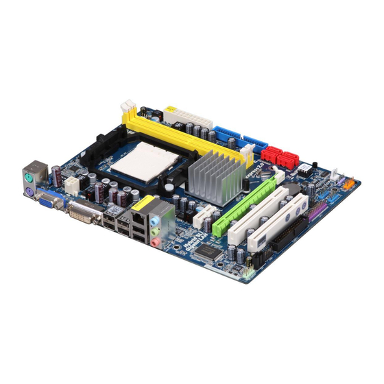
Page 12: Motherboard Layout
AM2 940-Pin CPU Socket System Panel Header (PANEL1, Orange) CPU Heatsink Retention Module USB 2.0 Header (USB8_9, Blue) 2 x 240-pin DDR2 DIMM Slots USB 2.0 Header (USB6_7, Blue) (Dual Channel: DDRII_1, DDRII_2; Yellow) Infrared Module Header (IR1) CPU Fan Connector (CPU_FAN1) -
Page 13: I/O Panel
VGA/D-Sub Port Microphone (Pink) PS/2 Keyboard Port (Purple) USB 2.0 Ports (USB01) * There are two LED next to the LAN port. Please refer to the table below for the LAN port LED indications. LAN Port LED Indications ACT/LINK SPEED... -
Page 14: Installation Installation
Installation Installation Installation This is a Micro ATX form factor (9.6-in x 7.5-in, 24.4 cm x 19.1 cm) motherboard. Before you install the motherboard, study the configuration of your chassis to en- sure that the motherboard fits into it. Pre-installation Precautions... -
Page 15: Cpu Installation
Step 4. When the CPU is in place, press it firmly on the socket while you push down the socket lever to secure the CPU. The lever clicks on the side tab to indicate that it is locked. -
Page 16: Installation Of Memory Modules (Dimm)
DIMMs or the system components. Step 1. Unlock a DIMM slot by pressing the retaining clips outward. Step 2. Align a DIMM on the slot such that the notch on the DIMM matches the break on the slot. notch break... -
Page 17: Expansion Slots (Pci And Pci Express Slots)
PCI slots: PCI slots are used to install expansion cards that have the 32-bit PCI interface. PCIE slots: PCIE1 (PCIE x1 slot; White) is used for PCI Express cards with x1 lane width cards, such as Gigabit LAN card, SATA2 card, etc. -
Page 18: Hybrid Sli Tm Operation Guide
HybridPower enables users to switch off the discrete GPU when the higher processing power of the discrete GPU is not required and use the motherboard GPU for non intensive graphics applications. Switching off the discrete GPU not only lowers the total system power consumption for everyday computing tasks like browsing the Web, word processing, or watching HD videos but also lowers total system noise. - Page 19 Supported PCI Express Card for Hybrid SLI ® GeForce Boost and HybridPower features are supported only with certain set of discrete GPUs. Please refer to our website for the graphics cards update in the future. For GeForce ® Boost Vendor Chipset...
- Page 20 ..\Drivers\Hybrid SLI driver\Vista * Currently, Hybrid SLI driver only has Vista 32 version, please visit our website for future update. Step 5. Restart your computer. Then you will find the Hybrid icon on your Win- ® dows taskbar. ® Step 6.
- Page 21 Vista 32 version, please visit our website for future update. Step 5. Restart your computer. Then you will find the Hybrid icon on your Win- dows ® taskbar. Please click the icon and select the item “Additional Displays”.
-
Page 22: Dual Monitor And Surround Display Features
To enable dual monitor feature, please follow the below steps: 1. Connect the DVI-D monitor cable to the VGA/DVI-D port on the I/O panel of this motherboard. Connect the D-Sub monitor cable to the VGA/D-Sub port on the I/O panel of this motherboard. - Page 23 PCI Express VGA card to PCI Express slot. Please refer to page 17 for proper expansion card installation procedures for details. 2. Connect the DVI-D monitor cable to the VGA/DVI-D port on the I/O panel of this motherboard. Connect the D-Sub monitor cable to the VGA/D-Sub port on the I/O panel of this motherboard.
- Page 24 A. Click the number ”2” icon. B. Click the items “This is my main monitor” and “Extend the desktop onto this monitor”. C. Click “OK” to save your change. D. Repeat steps A through C for the display icon identified by the number three and four.
-
Page 25: Hdmi Audio Function Operation Guide
The DVI-D port for the chipset adopted on this motherboard can support DVI/HDCP and HDMI format signal. You may use the DVI to HDMI adapter to convert the DVI-D port to HDMI interface. Please follow below steps to enable HDMI audio function according to the OS you install. -
Page 26: Jumpers Setup
CLRCMOS1 for 5 seconds. However, please do not clear the CMOS right after you update the BIOS. If you need to clear the CMOS when you just finish updating the BIOS, you must boot up the system first, and then shut it down... -
Page 27: Onboard Headers And Connectors
(33-pin FLOPPY1) FLOPPY1 Pin1 (see p.12, No. 22) the red-striped side to Pin1 Note: Make sure the red-striped side of the cable is plugged into Pin1 side of the connector. Primary IDE connector (Blue) (39-pin IDE1, see p.12, No. 8) IDE1... - Page 28 HDA to function correctly. Please follow the instruction in our manual and chassis manual to install your system. 2. If you use AC’97 audio panel, please install it to the front panel audio header as below: A.
- Page 29 ® For Windows XP / XP 64-bit OS: Please select “Front Mic” as default record device. If you want to hear your voice through front mic, please deselect "Mute" icon in “Front Mic” of “Playback” portion. For Windows ® Vista...
- Page 30 Though this motherboard provides 4-Pin CPU fan (Quiet Fan) support, the 3-Pin CPU fan still can work successfully even without the fan speed control function. If you plan to connect the 3-Pin CPU fan to the CPU fan connector on this motherboard, please connect it to Pin 1-3.
-
Page 31: Sataii Hard Disk Setup Guide
Before installing SATAII hard disk to your computer, please carefully read below SATAII hard disk setup guide. Some default setting of SATAII hard disks may not be at SATAII mode, which operate with the best performance. In order to enable SATAII function, please follow the below instruction with different vendors to correctly adjust your SATAII hard disk to SATAII mode in advance;... -
Page 32: Installation
STEP 3: Connect one end of the SATA data cable to the motherboard’s SATAII connector. STEP 4: Connect the other end of the SATA data cable to the SATA / SATAII hard disk. If you plan to use RAID 0, RAID 1 or JBOD function, you need to install at least 2 SATA / SATAII hard disks. -
Page 33: Sata / Sataii Hdd Hot Plug Feature And Operation Guide
SATA / SATAII driver is available on our support website: www.asrock.com 4. Make sure to use the SATA power cable & data cable, which are from our motherboard package. 5. Please follow below instructions step by step to reduce the risk of HDD crash... - Page 34 Please do follow below instruction sequence to process the Hot Unplug, improper procedure will cause the SATA / SATAII HDD damage and data loss. Step 1 Unplug SATA data cable from SATA / SATAII HDD side. Unplug SATA 15-pin power cable connector (Black) from SATA / SATAII HDD side. Step 2...
-
Page 35: Driver Installation Guide
2 . 1 4 Driver Installation Guide To install the drivers to your system, please insert the support CD to your optical drive first. Then, the drivers compatible to your system can be auto-detected and listed on the support CD driver page. Please follow the order from up to bottom side to install those required drivers. -
Page 36: Tm Tm
SATA / SATAII driver diskette containing the NVIDIA ® AHCI driver. After reading the floppy disk, the drivers will be presented. Select the driver to install according to the OS you install. The drivers are as below: A. NVIDIA nForce Storage Controller (required) Windows XP B. -
Page 37: Tm / Vista Tm 64-Bit
IDE Configuration. Set the “SATA Operation Mode” option to [IDE]. STEP 2: Make a SATA / SATAII driver diskette. Please make a SATA / SATAII driver diskette by following section 2.15.1 step 2 on page 35. STEP 3: Set Up BIOS. -
Page 38: Installing Windows
SATA / SATAII driver diskette containing the NVIDIA ® RAID driver. After reading the floppy disk, the drivers will be presented. Select the drivers to install. The drivers are as below: A. NVIDIA RAID Driver (required) B. NVIDIA nForce Storage Controller (required) ®... -
Page 39: Untied Overclocking Technology
Untied Overclocking function, please enter “Overclock Mode” option of BIOS setup to set the selection from [Auto] to [CPU, PCIE, Async.]. Therefore, CPU FSB is untied during overclocking, but PCI / PCIE buses are in the fixed mode so that FSB can operate under a more stable overclocking environment. -
Page 40: Bios S
Power-On-Self-Test (POST) to enter the BIOS SETUP UTILITY, otherwise, POST will continue with its test routines. If you wish to enter the BIOS SETUP UTILITY after POST, restart the system by press- ing <Ctl> + <Alt> + <Delete>, or by pressing the reset button on the system chassis. -
Page 41: Navigation Keys
To jump to the Exit Screen or exit the current screen Main Screen Main Screen Main Screen Main Screen Main Screen When you enter the BIOS SETUP UTILITY, the Main screen will appear and display the system overview. BIOS SETUP UTILITY Smart Advanced H/W Monitor... -
Page 42: Smart Screen
3.3 Smart Screen Smart Screen Smart Screen Smart Screen Smart Screen In the Smart screen, you can load the BIOS setup according to your requirements. BIOS SETUP UTILITY Main Smart Advanced H/W Monitor Boot Security Exit Exit system setup Smart Settings after saving the changes. -
Page 43: Advanced Screen
MS-DOS or Windows . Just launch this tool and save the new BIOS file to your USB flash drive, floppy disk or hard drive, then you can update your BIOS only in a few clicks without preparing an additional floppy diskette or other complicated flash utility. -
Page 44: Cpu Configuration
(C) Copyright 1985-2003, American Megatrends, Inc. AM2 Boost This option appears only when you adopt AM2 CPU. If you set this option to [Enabled], you will enable ASRock AM2 Boost function, which will improve the memory performance. The default value is [Disabled]. Please refer to caution 15 on page 9 for details. - Page 45 It will display Processor Maximum Voltage for reference. Multiplier/Voltage Change This item is set to [Auto] by default. If it is set to [Manual], you may adjust the value of Processor Frequency and Processor Voltage. However, it is recom- mended to keep the default value for system stability.
- Page 46 Processor Voltage This option appears only when you adopt AM2 CPU. This item will show when “Multiplier/Voltage Change” is set to [Manual]; otherwise, it will be hidden. The range of the value depends on the CPU you adopt on this motherboard. However, for safety and system stability, it is not recommended to adjust the value of this item.
-
Page 47: Memory Configuration
(C) Copyright 1985-2003, American Megatrends, Inc. Memory Clock This item can be set by the code using [Auto]. You can set one of the standard values as listed: [200 MHz (DDR2 400)], [266 MHz (DDR2 533)], [333 MHz (DDR2 667)] and [400MHz (DDR2 800)]. If you adopt Phenom CPU, there is one more option: [533MHz (DDR2 1066)]. - Page 48 Use this to adjust TRAS values. Configuration options: [Auto], [5CLK] to [18CLK]. The default value is [Auto]. TRTP Use this to adjust TRTP values. Configuration options: [Auto], [2-4 CLK] and [3-5 CLK]. The default value is [Auto]. TRRD Use this to adjust TRRD values. Configuration options: [Auto], [2CLK] to [5CLK].
- Page 49 MA Timing Use this to adjust values for MA timing. Configuration options: [Auto], [2T], [1T]. The default value is [Auto]. CHA Addr/Cmd Fine Delay Use this to adjust values for CHA Addr/Cmd Fine Delay feature. Configura- tion options: [Auto], [No Delay], [1/64CLK] to [31/64CLK]. The default value is [Auto].
- Page 50 CHA Processor ODT Use this to adjust values for CHA Processor ODT. Configuration options: [Auto], [300 ohms], [150 ohms] and [75 ohms]. The default value is [Auto]. CHB CKE Drive Strength Use this to adjust values for CHB CKE Drive Strength. Configuration options: [Auto], [1.00x], [1.25x], [1.50x] and [2.00x].
-
Page 51: Chipset Configuration
This item will switch the PCI Bus scanning order while searching for video card. It allows you to select the type of Primary VGA in case of multiple video controllers. The default value of this feature is [PCI]. Configuration options:... - Page 52 [1.15V], [1.20V] and [1.25V]. The default value is [Auto]. IGPU Boost This allows you to enable or disable the IGPU Boost feature. If you select [Enabled], iGPU will be in overclocking mode, which will increase the system performance but may affect the system stability. If you select [Disabled], iGPU...
-
Page 53: Acpi Configuration
Use this item to enable or disable Ring-In signals to turn on the system from the power-soft-off mode. PCI Devices Power On Use this item to enable or disable PCI devices to turn on the system from the power-soft-off mode. PS/2 Keyboard Power On Use this item to enable or disable PS/2 keyboard to turn on the system from the power-soft-off mode. -
Page 54: Storage Configuration
* If you select [RAID] mode, SATA / SATAII HDDs can not be accessed until you finish configuring RAID functions in NVIDIA BIOS / Windows RAID Utility. * If you install OS on SATA / SATAII HDDs, please do not change the setting of this item after OS installation. - Page 55 [ARMD]: This is used for IDE ARMD (ATAPI Removable Media Device), such as MO. LBA/Large Mode Use this item to select the LBA/Large mode for a hard disk > 512 MB under DOS and Windows; for Netware and UNIX user, select [Disabled] to disable the LBA/Large mode.
-
Page 56: Pcipnp Configuration
Use this item to enable or disable the S.M.A.R.T. (Self-Monitoring, Analysis, and Reporting Technology) feature. Configuration options: [Disabled], [Auto], [Enabled]. 32Bit Data Transfer Use this item to enable 32-bit access to maximize the IDE hard disk data transfer rate. 3.4.6 3.4.6 3.4.6 PCIPnP Configuration... -
Page 57: Floppy Configuration
Use this item to enable or disable floppy drive controller. Serial Port Address Use this item to set the address for the onboard serial port or disable it. Configuration options: [Disabled], [3F8 / IRQ4], [2F8 / IRQ3], [3E8 / IRQ4], [2E8 / IRQ3]. -
Page 58: Usb Configuration
Parallel Port Address Use this item to set the address for the onboard parallel port or disable it. Configuration options: [Disabled], [378], and [278]. Parallel Port Mode Use this item to set the operation mode of the parallel port. The default value is [ECP+EPP]. -
Page 59: Hardware Health Event Monitoring Screen
(C) Copyright 1985-2003, American Megatrends, Inc. CPU Quiet Fan This item allows you to control the CPU fan speed and fan noise. If you set this option as [Disabled], the CPU fan will operate in full speed. If you set this option as [Enabled], you will find the items “Target CPU Temperature”... -
Page 60: Boot Screen
Boot Screen Boot Screen Boot Screen Boot Screen Boot Screen In this section, it will display the available devices on your system for you to config- ure the boot settings and the boot priority. BIOS SETUP UTILITY Main Smart Advanced... -
Page 61: Security Screen
Boot From Onboard LAN Use this item to enable or disable the Boot From Onboard LAN feature. Boot Up Num-Lock If this item is set to [On], it will automatically activate the Numeric Lock function after boot-up. Security Screen Security Screen... -
Page 62: Exit Screen
BIOS SETUP UTILITY. Discard Changes and Exit When you select this option, it will pop-out the following message, “Dis- card changes and exit setup?” Select [OK] to exit the BIOS SETUP UTILITY without saving any changes. Discard Changes When you select this option, it will pop-out the following message, “Dis-... -
Page 63: Software Support Software Support
4.2.1 Running The Support CD 4.2.1 Running The Support CD To begin using the support CD, insert the CD into your CD-ROM drive. The CD automatically displays the Main Menu if “AUTORUN” is enabled in your computer. If the Main Menu did not appear automatically, locate and double click on the file “ASSETUP.EXE”...