ASROCK ALIVENF6P-VSTA User Manual
Hide thumbs
Also See for ALIVENF6P-VSTA:
- Installation manual (23 pages) ,
- Installation manual (185 pages)

Related Manuals for ASROCK ALIVENF6P-VSTA


Summary of Contents for ASROCK ALIVENF6P-VSTA
-
Page 1: User Manual
ALiveNF6P-VSTA User Manual Version 1.1 Published November 2007 Copyright©2007 ASRock INC. All rights reserved. 1 1 1 1 1... - Page 2 (including damages for loss of profits, loss of business, loss of data, interruption of business and the like), even if ASRock has been advised of the possibility of such damages arising from any defect or error in the manual or product.
-
Page 3: Table Of Contents
2.10 Serial ATA (SATA) / Serial ATAII (SATAII) Hard Disks Installation ................. 24 2.11 Hot Plug and Hot Swap Functions for SATA / SATAII HDDs ..24 2.12 SATA / SATAII HDD Hot Plug Feature and Operation Guide ..25 2.13 Driver Installation Guide ............. - Page 4 3.3.5 PCIPnP Configuration ............41 3.3.6 Floppy Configuration ............42 3.3.7 Super IO Configuration ............ 42 3.3.8 USB Configuration ............43 Hardware Health Event Monitoring Screen ......... 44 Boot Screen ................45 3.5.1 Boot Settings Configuration ..........45 Security Screen ................. 46 Exit Screen ................
-
Page 5: Introduction Introduction
ASRock’s commitment to quality and endurance. In this manual, chapter 1 and 2 contain introduction of the motherboard and step-by- step guide to the hardware installation. Chapter 3 and 4 contain the configuration guide to BIOS setup and information of the Support CD. -
Page 6: Specifications
Specifications Specifications Specifications Specifications Specifications - Micro ATX Form Factor: 9.6-in x 7.7-in, 24.4 cm x 19.6 cm Platform - Socket AM2 for AMD Phenom X4 / X2, Athlon 64FX / 64X2 / X2 / 64 and Sempron Processors - AMD LIVE! Ready - Supports AMD’s Cool ‘n’... - Page 7 Overclocking may affect your system stability, or even cause damage to the components and devices of your system. It should be done at your own risk and expense. We are not responsible for possible damage caused by overclocking.
- Page 8 This motherboard supports ASRock AM2 Boost overclocking technology. If you enable this function in the BIOS setup, the memory performance will improve up to 12.5%, but the effect still depends on the AM2 CPU you adopt. Enabling this function will overclock the chipset/CPU reference clock. However, we can not guarantee the system stability for all CPU/DRAM configurations.
-
Page 9: Vista
Premium or Basic logo, please adjust ® the shared memory size of onboard VGA to 128MB or above. * If you plan to use external graphics card on this motherboard, please refer to Premium Discrete requirement at http://www.asrock.com * After June 1, 2007, all Windows... -
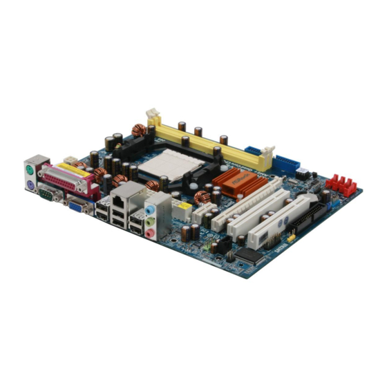
Page 10: Motherboard Layout
Primary IDE Connector (IDE1, Blue) (IR1) BIOS SPI Chip PCI Slots (PCI1- 2) NVIDIA GeForce 6150SE / nForce 430 Chipset 23 Internal Audio Connector: CD1 (Black) Chassis Speaker Header (SPEAKER 1) Front Panel Audio Header (HD_AUDIO1) SATAII Connector (SATAII_1 (PORT0), Red) -
Page 11: Asrock 6Ch I/O Plus
COM Port Line Out (Lime) PS/2 Keyboard Port (Purple) * To enable Multi-Streaming function, you need to connect a front panel audio cable to the front panel audio header. Please refer to below steps for the software setting of Multi-Streaming. ®... -
Page 12: Installation Installation
Installation Installation Installation This is a Micro ATX form factor (9.6-in x 7.7-in, 24.4 cm x 19.6 cm) motherboard. Before you install the motherboard, study the configuration of your chassis to en- sure that the motherboard fits into it. Pre-installation Precautions... -
Page 13: Cpu Installation
Step 4. When the CPU is in place, press it firmly on the socket while you push down the socket lever to secure the CPU. The lever clicks on the side tab to indicate that it is locked. -
Page 14: Installation Of Memory Modules (Dimm)
DIMMs or the system components. Step 1. Unlock a DIMM slot by pressing the retaining clips outward. Step 2. Align a DIMM on the slot such that the notch on the DIMM matches the break on the slot. notch break... -
Page 15: Expansion Slots (Pci Express And Pci Slots)
PCI slots: PCI slots are used to install expansion cards that have the 32-bit PCI interface. PCIE slots: PCIE1 (PCIE x1 slot) is used for PCI Express cards with x1 lane width cards, such as Gigabit LAN card, SATA2 card, etc. -
Page 16: Easy Multi Monitor Feature
® to page 15 for proper expansion card installation procedures for details. 2. Connect the D-Sub monitor cable to the VGA/D-Sub port on the I/O panel of this motherboard. Connect another D-Sub monitor cable to the VGA/D-Sub connector of the add-on PCI Express VGA card. Connect the DVI-D monitor cable to the VGA/DVI-D connector of the add-on PCI Express VGA card. -
Page 17: Jumpers Setup
CLRCMOS1 for 5 seconds. However, please do not clear the CMOS right after you update the BIOS. If you need to clear the CMOS when you just finish updating the BIOS, you must boot up the system first, and then shut it down... -
Page 18: Onboard Headers And Connectors
(33-pin FLOPPY1) FLOPPY1 Pin1 (see p.10 No. 18) the red-striped side to Pin1 Note: Make sure the red-striped side of the cable is plugged into Pin1 side of the connector. Primary IDE connector (Blue) (39-pin IDE1, see p.10 No. 7) IDE1... - Page 19 HDA to function correctly. Please follow the instruction in our manual and chassis manual to install your system. 2. If you use AC’97 audio panel, please install it to the front panel audio header as below: A.
- Page 20 Though this motherboard provides 4-Pin CPU fan (Quiet Fan) support, the 3-Pin CPU fan still can work successfully even without the fan speed control function. If you plan to connect the 3-Pin CPU fan to the CPU fan connector on this motherboard, please connect it to Pin 1-3.
- Page 21 (see p.10, No. 27) Though this motherboard provides 24-pin ATX power connector, it can still work if you adopt a traditional 20-pin ATX power supply. To use the 20-pin ATX power supply, please plug your power supply along with Pin 1 and Pin 13.
-
Page 22: Hdmi_Spdif Header Connection Guide
HDMI (High-Definition Multi-media Interface) is an all-digital audio/video specification, which provides an interface between any compatible digital audio/video source, such as a set-top box, DVD player, A/V receiver and a compatible digital audio or video monitor, such as a digital television (DTV). A complete HDMI system requires a HDMI VGA card and a HDMI ready motherboard with a HDMI_SPDIF header. -
Page 23: Sataii Hard Disk Setup Guide
Before installing SATAII hard disk to your computer, please carefully read below SATAII hard disk setup guide. Some default setting of SATAII hard disks may not be at SATAII mode, which operate with the best performance. In order to enable SATAII function, please follow the below instruction with different vendors to correctly adjust your SATAII hard disk to SATAII mode in advance;... -
Page 24: Installation
STEP 2: Connect the SATA power cable to the SATA / SATAII hard disk. STEP 3: Connect one end of the SATA data cable to the motherboard’s SATAII connector. STEP 4: Connect the other end of the SATA data cable to the SATA / SATAII hard disk. 2 . 1 1 2 . -
Page 25: Sata / Sataii Hdd Hot Plug Feature And Operation Guide
SATA / SATAII driver is available on our support website: www.asrock.com 4. Make sure to use the SATA power cable & data cable, which are from our motherboard package. 5. Please follow below instructions step by step to reduce the risk of HDD crash... - Page 26 Please do follow below instruction sequence to process the Hot Unplug, improper procedure will cause the SATA / SATAII HDD damage and data loss. Step 1 Unplug SATA data cable from SATA / SATAII HDD side. Unplug SATA 15-pin power cable connector (Black) from SATA / SATAII HDD side. Step 2...
-
Page 27: Driver Installation Guide
64-bit on your SATA / SATAII HDDs without RAID functions, ® you don’t have to make a SATA / SATAII driver diskette. Besides, there is no need for you to change the BIOS setting. You can start to install Windows 2000, Windows ®... -
Page 28: Installing Windows ® Vista Tm Tm
HDDs and want to manage (create, convert, delete, or rebuild) RAID functions on SATA / SATAII HDDs, you still need to set up “SATA Operation Mode” to [RAID] in BIOS first. Then, please set the RAID configuration by using the Windows RAID installation guide in the following path in the Support CD: .. -
Page 29: Untied Overclocking Technology
(create, convert, delete, or rebuild) RAID functions on SATA / SATAII HDDs, you still need to set up “SATA Operation Mode” to [RAID] in BIOS first. Then, please set the RAID configuration by using the Windows RAID installation guide in the following path in the Support CD: .. -
Page 30: Bios Setup Utility Bios Setup Utility
Power-On-Self-Test (POST) to enter the BIOS SETUP UTILITY, otherwise, POST will continue with its test routines. If you wish to enter the BIOS SETUP UTILITY after POST, restart the system by pressing <Ctl> + <Alt> + <Delete>, or by pressing the reset button on the system chassis. -
Page 31: Navigation Keys
To jump to the Exit Screen or exit the current screen <ESC> Main Screen Main Screen Main Screen Main Screen Main Screen When you enter the BIOS SETUP UTILITY, the Main screen will appear and display the system overview. BIOS SETUP UTILITY Advanced H/W Monitor Boot Security... -
Page 32: Advanced Screen
Advanced Screen Advanced Screen Advanced Screen Advanced Screen In this section, you may set the configurations for the following items: CPU Configuration, Chipset Configuration, ACPI Configuration, IDE Configuration, PCIPnP Configuration, Floppy Configuration, SuperIO Configuration, and USB Configuration. BIOS SETUP UTILITY... -
Page 33: Cpu Configuration
(C) Copyright 1985-2003, American Megatrends, Inc. AM2 Boost If you set this option to [Enabled], you will enable ASRock AM2 Boost function, which will improve the memory performance. The default value is [Disabled]. Please refer to caution 7 on page 8 for details. - Page 34 It will display Processor Maximum Voltage for reference. Multiplier/Voltage Change This item is set to [Auto] by default. If it is set to [Manual], you may adjust the value of Processor Multiplier and Processor Voltage. However, it is recom- mended to keep the default value for system stability.
- Page 35 Memory Clock This item can be set by the code using [Auto]. You can set one of the standard values as listed: [200MHz (DDRII400)], [266MHz (DDRII533)], [333MHz (DDRII667)] and [400MHz (DDRII800)]. Flexibility Option The default value of this option is [Disabled]. It will allow better tolerance for memory compatibility when it is set to [Enabled].
- Page 36 Use this to adjust values for MA timing. Configuration options: [Auto], [2T], [1T]. The default value is [Auto]. Bank Interleaving Interleaving allows memory accesses to be spread out over banks on the same node, or accross nodes, decreasing access contention.
-
Page 37: Chipset Configuration
Primary Graphics Adapter This item will switch the PCI Bus scanning order while searching for video card. It allows you to select the type of Primary VGA in case of multiple video controllers. The default value of this feature is [PCI]. Configuration options: [PCI], [Onboard] and [PCI Express]. -
Page 38: Acpi Configuration
Use this item to enable or disable Ring-In signals to turn on the system from the power-soft-off mode. PCI Devices Power On Use this item to enable or disable PCI devices to turn on the system from the power-soft-off mode. PS/2 Keyboard Power On Use this item to enable or disable PS/2 keyboard to turn on the system from the power-soft-off mode. -
Page 39: Ide Configuration
[non-RAID]. If you want to operate RAID function on SATA / SATAII HDDs, please select [RAID]. * If you select [RAID] mode, SATA / SATAII HDDs can not be accessed until you finish configuring RAID functions in NVIDIA BIOS / Windows RAID Utility. - Page 40 [ARMD]: This is used for IDE ARMD (ATAPI Removable Media Device), such as MO. LBA/Large Mode Use this item to select the LBA/Large mode for a hard disk > 512 MB under DOS and Windows; for Netware and UNIX user, select [Disabled] to disable the LBA/Large mode.
-
Page 41: Pcipnp Configuration
Use this item to enable or disable the S.M.A.R.T. (Self-Monitoring, Analysis, and Reporting Technology) feature. Configuration options: [Disabled], [Auto], [Enabled]. 32Bit Data Transfer Use this item to enable 32-bit access to maximize the IDE hard disk data transfer rate. 3.3.5 3.3.5 3.3.5 PCIPnP Configuration... -
Page 42: Floppy Configuration
Use this item to enable or disable floppy drive controller. Serial Port Address Use this item to set the address for the onboard serial port or disable it. Configuration options: [Disabled], [3F8 / IRQ4], [2F8 / IRQ3], [3E8 / IRQ4], [2E8 / IRQ3]. -
Page 43: Usb Configuration
Parallel Port Address Use this item to set the address for the onboard parallel port or disable it. Configuration options: [Disabled], [378], and [278]. Parallel Port Mode Use this item to set the operation mode of the parallel port. The default value is [ECP+EPP]. -
Page 44: Hardware Health Event Monitoring Screen
Hardware Health Event Monitoring Screen Hardware Health Event Monitoring Screen In this section, it allows you to monitor the status of the hardware on your system, including the parameters of the CPU temperature, motherboard temperature, CPU fan speed, chassis fan speed, and the critical voltage. -
Page 45: Boot Screen
Boot Screen Boot Screen Boot Screen Boot Screen Boot Screen In this section, it will display the available devices on your system for you to config- ure the boot settings and the boot priority. BIOS SETUP UTILITY Main Advanced H/W Monitor... -
Page 46: Security Screen
Security Screen Security Screen Security Screen Security Screen Security Screen In this section, you may set or change the supervisor/user password for the system. For the user password, you may also clear it. BIOS SETUP UTILITY Main Advanced H/W Monitor... -
Page 47: Exit Screen
BIOS SETUP UTILITY. Discard Changes and Exit When you select this option, it will pop-out the following message, “Dis- card changes and exit setup?” Select [OK] to exit the BIOS SETUP UTILITY without saving any changes. Discard Changes When you select this option, it will pop-out the following message, “Dis-... -
Page 48: Software Support
4.2.1 Running The Support CD 4.2.1 Running The Support CD To begin using the support CD, insert the CD into your CD-ROM drive. The CD automatically displays the Main Menu if “AUTORUN” is enabled in your computer. If the Main Menu did not appear automatically, locate and double click on the file “ASSETUP.EXE”...