Table of Contents
Advertisement
Quick Links
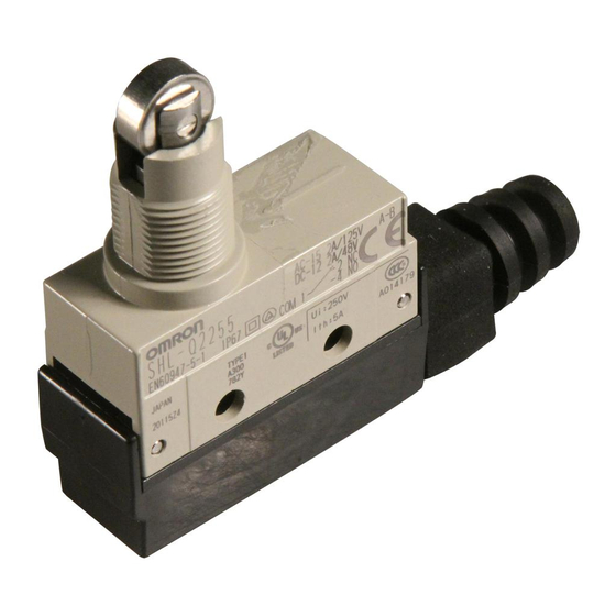
Enclosed Switch
SHL
Subminiature Enclosed Switch (Measuring
48 x 17.5 x 45 mm) with High Sealing
Property
• Built-in coil spring type basic switch housed in rigid zinc diecast
alloy casting boasts long life and high precision.
• Requires nearly the same operating force as conventional basic
precision switches (2.35 to 3.92 N).
• Molded terminal model is available.
• Operation indicator model is also available.
Model Number Structure
■ Model Number Legend
Standard Models
SHL-@55-@
1
2
1. Actuator
D:
Plunger
Q:
Panel mount plunger
Q22: Panel mount roller plunger
Q21: Panel mount crossroller plunger
W:
Short hinge lever
W1:
Hinge lever
W2:
Short hinge roller lever
W21: Hinge roller lever
W3:
One-way action short hinge roller lever
W31: One-way action hinge roller lever
Ordering Information
■ List of Models
Actuator
Plunger
Panel mount plunger
Panel mount roller plunger
Panel mount crossroller plunger
Short hinge lever
2. Rated Current
Note: Refer to page 53 for Molded Terminal Models.
Standard model
SHL-D55
SHL-Q55
SHL-Q2255
SHL-Q2155
SHL-W55
None: Standard
01:
Micro Load
Micro voltage
SHL-D55-01
SHL-Q55-01
SHL-Q2255-01
SHL-Q2155-01
SHL-W55-01
Enclosed Switch
SHL
F-45
Advertisement
Table of Contents

Related Manuals for Omron SHL


Summary of Contents for Omron SHL
-
Page 1: Standard Models
48 x 17.5 x 45 mm) with High Sealing Property • Built-in coil spring type basic switch housed in rigid zinc diecast alloy casting boasts long life and high precision. • Requires nearly the same operating force as conventional basic precision switches (2.35 to 3.92 N). -
Page 2: Specifications
DC-12 2 A/24 V SHL-@55-01L4 DC-12 0.1 A/24 V 0.5 A SHL-@55-L5 DC-12 2 A/48 V SHL-@55-01L5 DC-12 0.1 A/48 V 0.5 A Note: For details on the above models, refer to Model Number Legend under Molded Terminal Models. F-46 Enclosed Switch... - Page 3 Note: 1. The above figures are for steady-state currents. 2. Inductive loads have a power factor of 0.4 min. (AC) and a time constant of 7 ms max. (DC). 3. Lamp load has an inrush current of 10 times the steady-state current.
- Page 4 3. The head section of the plunger type SHL-D(Q)@@ is excluded. 4. Durability values are calculated at an operating temperature of 5 C to 35 C, and an operating humidity of 40% to 70%. Contact your OMRON sales representative for more detailed information on other operating environments.
-
Page 5: Engineering Data
■ Contact Form 2 (NC) (COM) 1 4 (NO) EN60947-5-1 Engineering Data ■ Electrical Durability Ambient temperature: 5˚C to 35˚C Ambient humidity: 40% to 50% Operating frequency: 30 operations/min. (cosφ = 1) 250 VAC Switching current (A) Nomenclature Movable plunger... - Page 6 Dimensions Note: 1. All units are in millimeters unless otherwise indicated. 2. Unless otherwise specified, a tolerance of 0.4 mm applies to all dimensions. Plunger 7.8 dia. (see note) Two, 4.2 dia. SHL-D55, SHL-D55-01 holes × 16.9 15 × 15...
- Page 7 = 1 (see note) 17.5 Note: Stainless steel lever 16.9 16.5±0.2 15 × 15 Short Hinge Roller Lever 9.5 dia. × 4.8 (see note) SHL-W255, SHL-W255-01 Note: Sintered stainless roller 16.9 16.5±0.2 15 × 15 Hinge Roller Lever 9.5 dia. × 4.8 (see note)
- Page 8 One-way Action Short Hinge Roller Lever 9.5 dia. × 4.8 (see note) SHL-W355, SHL-W355-01 Operating direction 35.5R 90° Note: Stainless sintered roller 16.9 16.5±0.2 15 × 15 9.5 dia. × 4.8 (see note) One-way Action Hinge Roller Lever SHL-W3155, SHL-W3155-01 90°...
- Page 9 Use of the molded terminal model is recommended in locations subject to excessive dust, oil drips, or moisture. All types of SHL Switches can be fabricated into a molded terminal version. In this case, the molded terminal model will have the same dimensions an operating characteristics as the basic model from which the molded terminal model is fabricated.
-
Page 10: Tightening Torque
When mounting the panel mount-type Switch with screws on a side surface, remove the hexagonal nuts from the actuator. Be sure to connect a fuse with a breaking current 1.5 to 2 times the Mounting Holes rated current to the Limit Switch in series in order to protect the Limit Switch from damage due to short-circuiting. - Page 11 100 mA 160 mA 1,000 Current (mA) The above diagram is for standard conditions (5 C to 35 C, 40% to 70%). Since the values vary depending on the operating environ- ment conditions, contact your OMRON representative for further details.
- Page 12 ALL DIMENSIONS SHOWN ARE IN MILLIMETERS. To convert millimeters into inches, multiply by 0.03937. To convert grams into ounces, multiply by 0.03527. In the interest of product improvement, specifications are subject to change without notice. Cat. No. C026-E1-09 F-56 Enclosed Switch...