Advertisement
Quick Links
Instructions
CARBON STEEL
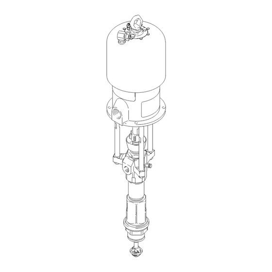
Check–Mate™ 800 Pumps
With Priming Piston and Severe–Duty Rod and Cylinder
Refer to page 2 for Table of Contents.
US Patent Nos. 5,147,188 and 5,154,532.
Other patents pending.
Important Safety Instructions
Read all warnings and instructions in this manual.
Save these instructions. See page 2 for model
numbers and maximum working pressures.
Models 198466
and 246938
GRACO INC. P.O. BOX 1441 MINNEAPOLIS, MN 55440-1441
Copyright 1995, Graco Inc. is registered to I.S. EN ISO 9001
Parts
Models 237265,
246940 and 246941
ti1447a
308351K
Models 236471
and 246942
4990B
04995
Advertisement

Related Manuals for Graco Check–Mate 800 Series


Summary of Contents for Graco Check–Mate 800 Series
- Page 1 Save these instructions. See page 2 for model numbers and maximum working pressures. Models 237265, 246940 and 246941 Models 198466 and 246938 04995 4990B ti1447a GRACO INC. P.O. BOX 1441 MINNEAPOLIS, MN 55440-1441 Copyright 1995, Graco Inc. is registered to I.S. EN ISO 9001...
- Page 2 ......Graco Standard Warranty ..... .
- Page 3 D This equipment is for professional use only. D Read all instruction manuals, tags, and labels before operating the equipment. D Use the equipment only for its intended purpose. If you are not sure, call your Graco distributor. D Do not alter or modify this equipment.
- Page 4 WARNING SKIN INJECTION HAZARD Spray from the spray gun/dispense valve, leaks or ruptured components can inject fluid into your body and cause extremely serious injury, including the need for amputation. Fluid splashed in the eyes or on the skin can also cause serious injury. D Fluid injected into the skin might look like just a cut, but it is a serious injury.
- Page 5 WARNING FIRE AND EXPLOSION HAZARD Improper grounding, poor ventilation, open flames or sparks can cause a hazardous condition and result in a fire or explosion and serious injury. D Ground the equipment and the object being sprayed. Refer to Grounding on page 6. D If there is any static sparking or you feel an electric shock while using this equipment, stop spray- ing/dispensing immediately.
- Page 6 Installation Grounding WARNING FIRE AND EXPLOSION HAZARD Before operating the pump, ground the system as explained below. Also read the section FIRE AND EXPLOSION HAZARD on page 5. 0864 Fig. 2 1. King Pumps: use a ground wire and clamp. See Fig.
- Page 7 Pump dimensions and the mounting hole layout are shown on page 49. Accessories are available from Graco. If you supply If you are mounting the pump on a ram, refer to the your own accessories, be sure they are adequately separate ram manual for installation and operation sized and pressure–rated to meet the system’s re-...
- Page 8 Installation (Air–Powered Pumps) Pump M Fluid Drain Valve (required) 200 Liter (55 Gallon) Air-Powered Ram Electrically Conductive Fluid Supply Hose Main Air Bleed Valve (required, for pump and ram) Fluid Shutoff Valve Air Line Lubricator (position only) Gun/Valve Swivel Pump Air Bleed Valve (required, for pump) Airless Spray Gun or Dispensing Valve Pump Air Regulator Ram Air Regulator...
- Page 9 Installation (Air–Powered Pumps) D A pump runaway valve (V) senses when the WARNING pump is running too fast and automatically shuts off the air to the motor. A pump which runs too fast can A main air bleed valve (C), pump air bleed valve be seriously damaged.
- Page 10 Installation (Hydraulic–Powered Pumps) Accessory Pump Stand Hydraulic Pressure Gauge (P/N 218742) Flow Control Valve Surge Tank (P/N 218509 or Pressure Reducing Valve 238983) Drain Line 50 mm (2 in.) Diameter Pipe M Hydraulic Return Line Full Flow, Non-Restrictive Shutoff Valve Fluid Shutoff Valve Accumulator Fluid Supply Line...
- Page 11 Installation (Hydraulic–Powered Pumps) NOTE: Hydraulic fluid is exhausted from differential CAUTION hydraulic motors only on the upstroke of the operating cycle. The oil return line must have at least twice the The Hydraulic Power Supply must be kept clean at flow capacity as the oil supply line.
- Page 12 Now clear the tip/nozzle or hose. Torque to 128–156 N.m (95–115 ft-lb). Packing Nut/Wet-Cup Before starting, fill the packing nut (2) 1/3 full with 04995 Fig. 5 Graco Throat Seal Liquid (TSL) or compatible solvent. See Fig. 5. 308351...
- Page 13 Operation Flush the Pump Before First Use WARNING COMPONENT RUPTURE HAZARD The pump is tested with lightweight oil, which is left in To reduce the risk of overpressurizing to protect the pump parts. If the fluid you are using your system, which could cause compo- may be contaminated by the oil, flush it out with a nent rupture and serious injury, never compatible solvent.
- Page 14 Operation Hydraulic–Powered Systems c. Adjust the pressure–reducing valve until you get the desired fluid pressure. Run the pump Refer to the warnings on page 13. until all air is purged from the fluid lines. 1. Supply fluid to the pump, per the requirements of d.
- Page 15 Notes 308351...
- Page 16 Maintenance Shutdown and Care of the Pump CAUTION WARNING Never leave water or water-base fluid in the pump overnight. If you are pumping water-base fluid, flush To reduce the risk of serious injury whenever you with water first, then with a rust inhibitor such as are instructed to relieve pressure, always follow the mineral spirits.
- Page 17 Turn on the air or hydraulic power just enough to start the pump. If the pump starts, the obstruction is in the fluid hose or gun. NOTE: If you experience air motor icing, call your Graco distributor. 308351...
- Page 18 Troubleshooting PROBLEM CAUSE SOLUTION Erratic or accelerated Exhausted fluid supply. Refill and prime. pump speed. Fluid is too heavy for pump priming. Use the bleeder valve (see page 13 or 14); use a ram. Held open or worn piston valve or seals. Clear the valve; replace the seals. Held open or worn priming piston.
- Page 19 6. Reconnect all hoses. Reconnect the ground wire if it was disconnected. Fill the wet-cup (2) 1/3 full of Graco Throat Seal Liquid or compatible solvent. 7. Turn on the power supply. Run the pump slowly to ensure proper operation.
- Page 20 Displacement Pump Service Disassembly NOTE: These instructions are written with the pump separating at joint A. If it separates at joints B or C, When disassembling the pump, lay out all the removed disassemble it at that joint, place the intake housing parts in sequence, to ease reassembly.
-
Page 21: Models
Displacement Pump Service 6. Pull the intake seat (37) and seal (38) out the bottom of the intake valve housing (17). Take care not to drop the check valve assembly (V) as it comes free, and set it aside for later. See Fig. 7. NOTE: If the seat (37) is difficult to remove, insert a See Fig. - Page 22 Displacement Pump Service 9. Remove the seal (8) from the bottom of the cylin- NOTE: The seal (39) is press-fit in the nut (15) and der (10). See Fig. 12. Shine a light into the cylinder may require cutting to ease removal. to examine the inside surface for scoring or dam- age.
-
Page 23: Models
Displacement Pump Service Reassembly 4. Lubricate the piston seal (13*) and install it on the piston seat (14). Apply thread sealant to the Fig. 16 shows a cutaway of the entire pump. threads of the seat and the piston guide (11). Screw the guide onto the seat (14). - Page 24 Displacement Pump Service 7. If the cylinder (10) was removed from the outlet 11. Lubricate the seal (8*) and install it on the bottom housing (9), lubricate the seal (8*) and place it on of the cylinder (10). Slide the intake valve housing the top of the cylinder.
- Page 25 Displacement Pump Service 15. Screw the intake cylinder (19) into the intake 18. Slide the priming piston (21) onto the rod (18) until housing (17). Using a pipe wrench on the hex of it stops. Hold the rod (18) steady with an adjust- the cylinder (19), torque the cylinder to 468–590 able wrench on the flats, and screw the seat (22) N.m (345–435 ft-lb).
- Page 26 Displacement Pump Service For Pumps 198466, 237265 and 236471 only THROAT PACKING DETAIL 17a, b, c Piston check valve (see Fig. 12). Intake check valve (see Fig. 13). Lubricate. Lips of v-packings must face down. Screw valve plug (20) completely into valve body (29). Torque to 128–156 N.m (95–115 ft-lb).
- Page 27 Displacement Pump Service For Pumps 246938, 246940, 246941 and 246942 only Servicing the Throat Packings 3. Place the flats of the packing nut (2) in a vise. Unscrew the packing housing (3) and discard it NOTE: The throat packings are available as a preas- and the packings.
-
Page 28: Models
Parts Part No. 236471 Pump, Series B, 65:1 Ratio, with King Air Motor Part No. 246942 Pump, Series A, 65:1 Ratio, with King Air Motor Part No. 237261 Pump, Series A, 31:1 Ratio, with Bulldog Air Motor Part No. 246940 Pump, Series A, 31:1 Ratio, with Bulldog Air Motor Part No. - Page 29 Parts Part No. 198475 Pump, Series A, 65:1 Ratio, with Quiet King Air Motor Ref. Part No. Description Qty. 235525 AIR MOTOR, Quiet King See 309348 for parts 198476 ROD, tie; 271 mm (10.67”) shoulder to shoulder 106166 NUT, hex; M16 x 2.0 186925 NUT, coupling 184129...
- Page 30 Parts Part No. 198466 Pump, Series A, with Viscount II Hydraulic Motor Part No. 246938 Pump, Series A, with Viscount II Hydraulic Motor Ref. Part No. Description Qty. 198468 MOTOR, Viscount II See 307158 for parts 198471 ROD, tie; 235 mm (9.25”) shoulder to shoulder 106166 NUT, hex;...
- Page 31 Parts Part No. 237265 Pump, Series B, 65:1 Ratio, with Reduced Icing Quiet King Air Motor Part No. 240945 Pump, Series B, 65:1 Ratio, with Quiet King Air Motor Part No. 253376 Pump, Series B, 65:1 Ratio, with Quiet King Air Motor Part No.
- Page 32 Displacement Pump Parts Part No. 246939, Series A, Part Part Description Description 189317 ROD, displacement; stainless steel 190128 PLUG, bleeder valve; carbon steel 237799 PACKING NUT/WET-CUP; 276378 PISTON, priming; stainless steel carbon steel 184246 GLAND, intake valve, male; 190585 HOUSING, throat seal; carbon steel carbon steel 109301...
- Page 33 Displacement Pump Parts 17a, b, c 04989 308351...
- Page 34 Displacement Pump Parts Part No. 236611, 198469 and 237945; Series A NOTE: Refer to page 36 for the different packing configurations available. Part Part Description Description 189317 ROD, displacement; stainless steel 184400 ROD, priming piston; stainless steel 222995 PACKING NUT/WET-CUP; 189447 CYLINDER, intake;...
- Page 35 Displacement Pump Parts Intake Packing Stack. See page 36. Throat Packing Stack. See page 36. 17a, b, c 04989 308351...
- Page 36 Displacement Pump Parts Part No. 236611 and 198469, Series A, Standard UHMWPE/PTFE Packed Displacement Pump Part THROAT PACKINGS: INTAKE PACKINGS: LIPS FACE DOWN LIPS FACE UP Description LUBRICATE PACKINGS 109306 V-PACKING, throat; PTFE 184201 GLAND, throat, female; carbon steel 109256 V-PACKING, throat;...
- Page 37 Notes 308351...
-
Page 38: Mpa, 403 Bar (5850 Psi
Technical Data (Model 236471 and 246942 King Pumps) WARNING Be sure that all fluids and solvents used are chemically compatible with the Wetted Parts listed below. Always read the manufacturer’s literature before using fluid or solvent in this pump. Category Data Ratio 65:1... - Page 39 Technical Data (Model 236471 and 246942 King Pumps) Performance Charts To find Fluid Outlet Pressure (psi/MPa/bar) at a specific fluid flow To find Pump Air Consumption (m#/min or scfm) at a specific fluid (lpm/gpm) and operating air pressure (psi/MPa/bar): flow (lpm/gpm) and air pressure (psi/MPa/bar): 1.
- Page 40 Technical Data (Models 240945, 253376, and 198475 Quiet King Pump and Model 237265 Reduced Icing Quiet King Pump) WARNING Be sure that all fluids and solvents used are chemically compatible with the Wetted Parts listed below. Always read the manufacturer’s literature before using fluid or solvent in this pump.
- Page 41 Technical Data (Models 240945, 253376, and 198475 Quiet King Pump and Model 237265 Reduced Icing Quiet King Pump) Performance Charts To find Fluid Outlet Pressure (psi/MPa/bar) at a specific fluid flow To find Pump Air Consumption (m#/min or scfm) at a specific fluid (lpm/gpm) and operating air pressure (psi/MPa/bar): flow (lpm/gpm) and air pressure (psi/MPa/bar): 1.
- Page 42 Technical Data (Model 237261, 246940 and 241901 Bulldog Pumps) WARNING Be sure that all fluids and solvents used are chemically compatible with the Wetted Parts listed below. Always read the manufacturer’s literature before using fluid or solvent in this pump. Category Data Ratio...
- Page 43 Technical Data (Model 237261, 246940 and 241901 Bulldog Pump) Performance Charts To find Fluid Outlet Pressure (psi/MPa/bar) at a specific fluid flow To find Pump Air Consumption (m#/min or scfm) at a specific fluid (lpm/gpm) and operating air pressure (psi/MPa/bar): flow (lpm/gpm) and air pressure (psi/MPa/bar): 1.
- Page 44 Technical Data (Model 237274 Reduced Icing Quiet Bulldog Pump) WARNING Be sure that all fluids and solvents used are chemically compatible with the Wetted Parts listed below. Always read the manufacturer’s literature before using fluid or solvent in this pump. Category Data Ratio...
- Page 45 Technical Data (Model 237274 Reduced Icing Quiet Bulldog Pump) Performance Charts To find Fluid Outlet Pressure (psi/MPa/bar) at a specific fluid flow To find Pump Air Consumption (m#/min or scfm) at a specific fluid (lpm/gpm) and operating air pressure (psi/MPa/bar): flow (lpm/gpm) and air pressure (psi/MPa/bar): 1.
-
Page 46: Mpa, 8.4 Bar (120 Psi)
Technical Data (Model 237264 and 246941 Senator Pumps) WARNING Be sure that all fluids and solvents used are chemically compatible with the Wetted Parts listed below. Always read the manufacturer’s literature before using fluid or solvent in this pump. Category Data Ratio 19:1... -
Page 47: Mpa, 7 Bar (100 Psi)
Technical Data (Model 237264 and 246941 Senator Pumps) Performance Charts To find Fluid Outlet Pressure (psi/MPa/bar) at a specific fluid flow To find Pump Air Consumption (m#/min or scfm) at a specific fluid (lpm/gpm) and operating air pressure (psi/MPa/bar): flow (lpm/gpm) and air pressure (psi/MPa/bar): 1. - Page 48 Technical Data (Model 198466 and 246938 Viscount II Pumps) WARNING Be sure that all fluids and solvents used are chemically compatible with the Wetted Parts listed below. Always read the manufacturer’s literature before using fluid or solvent in this pump. Category Data Maximum fluid working pressure...
- Page 49 Dimensions and Mounting Hole Layout Model 236471 Shown All Models, except 198466 and 246938 94.28 mm (3.712”) 101.6 mm 94.28 mm (4.0”) (3.712”) 50.8 mm (2.0”) Three M16 x 2.0 Holes 11.1 mm (0.437”) 88 mm DIA (4) (3.464”) 0653 Model 198466 and 246938 287.2 mm 188.4 mm...
- Page 50 With the exception of any special, extended, or limited warranty published by Graco, Graco will, for a period of twelve months from the date of sale, repair or replace any part of the equipment determined by Graco to be defective.