Table of Contents
Advertisement
Quick Links
Advertisement
Table of Contents

Related Manuals for Axis HD1409Q


Summary of Contents for Axis HD1409Q
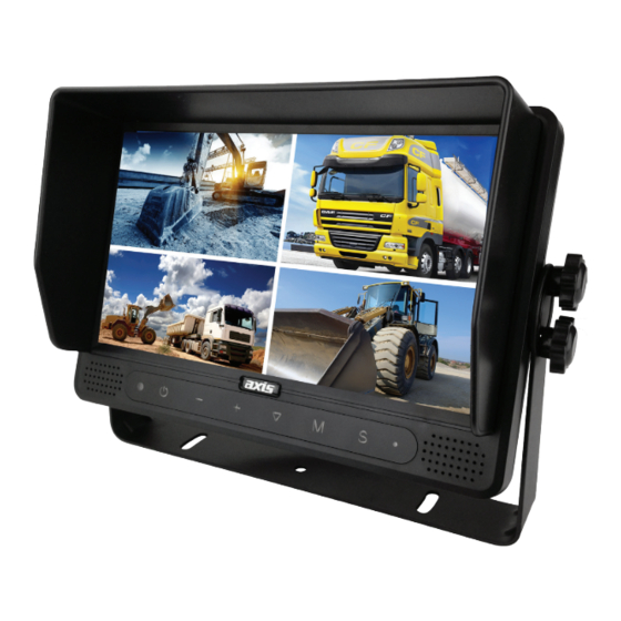
- Page 1 HD1409Q 9” High Resolution Quad View Monitor Version 1.1...
-
Page 2: Table Of Contents
Contents 1. Precautions ..................3 2. Features and Specifications ..............5 3. Accessories ..................6 4. Parts Identification ................7 5. Connections ..................8 6. Menu Operation ..................9 6.1 Desktop ..................9 6.2 Home Menu ................10 6.3 Volume ..................11 6.4 Brightness .................. 12 6.5 Mode .................. -
Page 3: Precautions
1. Precautions ⚫ Storage and Keeping Do not expose the monitor to excessive heat or cold. The storage temperature of this device is -30~+80℃, and the operating temperature is -20~+70℃. Never use this device near a bathtub, wash basin, kitchen, damp basement, swimming pool or similar places. - Page 4 ⚫ Maintenance Remove all the cable connections from the monitor before cleaning the device. Use a mild household detergent and clean the unit with a slightly damp, soft cloth. Never use strong solvents such as thinner or benzine, as they might damage the finish of the device.
-
Page 5: Features And Specifications
2. Features and Specifications 9" HD quad-view monitor, and resolution is 1024 x 600. Supports 4 HD camera inputs and split-view display mode. Multiple video formats available: 1080P30/1080P25/720P30/720P25/PAL/NTSC. Single, dual, triplex, quad, trefoil, Y-split, and PIP view display modes are available. Each channel supports independent image adjustment for horizontal-mirror, vertical-mirror view display. -
Page 6: Accessories
3. Accessories U-Support Bracket Center Mount Bracket Sun Shield Angle Adjustment Screws Power Cable... -
Page 7: Parts Identification
4. Parts Identification Power Indicator Loudspeaker Light Lever Sensor Digital Color LCD Screen, Touch Screen... -
Page 8: Connections
5. Connections Camera 1. Camera 2. Camera 3. Camera 4. Red wire - Positive voltage supply, connect to ACC 10-32V. Black wire - Negative voltage supply, connect to ground. White wire - Optional camera 1 trigger. (Do NOT connect to constant power or ACC). Blue wire - Optional camera 2 trigger. -
Page 9: Menu Operation
6. Menu Operation 6.1 Desktop Button Panel Instructions: ● Power: Enter/exit standby mode. ● +/-: Increase/decrease the volume. ● ▼: Switch display mode. ● M: Press for 3s to enable/disable the menu lock; short press to open home menu. Pic. 6.2.1-1 Touch Screen Instructions: ●... -
Page 10: Home Menu
Pic. 6.2.1-3 ● While the auto scan and trigger functions are inactive, and in split-screen mode (not PIP1/2/3 or SP), tap one of the channels to enter single view display of the channel, and tap again to enter split view. ●... -
Page 11: Volume
● ▼: Enter the chosen menu. ● M: Exit home menu. Pic.6.2.2 Touch Screen Instructions: ● Tap the icon to enter the corresponding menu. Tap the area outside the box to exit home menu. 6.3 Volume Button Panel Instructions: ● Power: Enter/exit standby mode. ●... -
Page 12: Brightness
● While muted, adjusting the scroll bar will disable the mute. 6.4 Brightness Button Panel Instructions: ● Power: Enter/exit standby mode. ● +/-: Increase/reduce the brightness. ● ▼: Switch the brightness scroll bar when the auto dim is on. ● M: Return to the previous menu. When auto dim is off: Pic.6.2.4-1 When auto dim is on:... -
Page 13: Split Setup
● ▼: Use cursor to select the display mode. If the icon is selected, the Advanced Split Setup menu will be displayed. ● M: Return to the previous menu. Pic.6.2.5 Touch Instructions: ● Tap the icon to switch to the corresponding display mode; if the icon is selected, the Advanced Split Setup menu will be displayed. - Page 14 Pic.6.2.5.1-2 Touch Instructions: ● Tap Layer 1-4/Audio icon to switch the page. ● When Layer 1-4 is selected: In this menu, you can open/close a camera window, adjust the size and position of each camera window, and move camera windows to the foreground/background. ●...
-
Page 15: Setting
6.6 Setting Button Panel Instructions: ● Power: Enter/exit standby mode. ● +/-: Move the cursor. ● ▼: Enter the chosen menu. ● M: Return to the previous menu. Pic.6.2.6 Touch Instructions: ● Tap the icon to enter the corresponding menu. 6.6.1 Camera Button Panel Instructions: ●... - Page 16 Pic.6.2.6.1-1 Touch Instructions: ● Tap the camera channel icons on the top to show the parameters of the corresponding channel. ● Tap the ON/OFF icons or drag the scroll bars to change the features. ● Tap the icon to edit the camera channel name. Features Instructions: ●...
-
Page 17: Parking Line
● Power: Enter/exit standby mode. ● +/-: Move the cursor. ● ▼: Select the chosen icon. ● M: Go back to the Camera menu without saving. Pic.6.2.6.1-2 Touch Instructions: ● Tap the letter icons to edit the channel name. Other Instructions: ●... - Page 18 ● ▼: Enter the chosen menu or change the state of ON/OFF/AUTO icons. ● M: Return to the previous menu. Pic.6.2.6.2-1 Touch Instructions: ● Tap the ON/OFF/AUTO icons to select the display methods of parking lines: AUTO (display when triggered) / ON (constantly on) / OFF. Tap the icon to enter parking lines calibration menu “Calibrate”.
- Page 19 Button Panel Adjustment Mode Instructions: Zoom horizontally. ● +/-: Horizontally magnify/ shrink the parking lines. Zoom vertically. ● +/-: Vertically magnify/ shrink the parking lines. Move horizontally. ● +/-: Parking lines move to the left/ right. Move vertically. ● +/-: Parking lines move up/down. Zoom integrally.
-
Page 20: Language
● SEL: Turn on/off adjustment assistance grids. ● P/N: Switch the current focuses. ● SYS: Resume the default config. ● AV: Switch the parking line types. Other Instructions: ● The coordinates of the current focus will be shown on the top left. ●... -
Page 21: Trigger
6.6.4 Trigger Pic.6.2.6.4 Button Panel Instructions: ● Power: Enter/exit standby mode. ● +/-: Move the cursor. ● ▼: Pop up the edit menu. ● M: Return to the previous menu. Touch Instruction ● Tap any of the “Delay” or “Priority” icons to activate the digital input box. Tap any of the “Display” icons to activate an interface to select display images. -
Page 22: Input Panel
● Trigger detection is supported in standby mode. 6.6.4.1 Input panel Button Panel Instructions: ● Power: Enter/exit standby mode. ● +/-: Move the cursor. ● ▼: Select the chosen icon. ● M: Return to the previous menu without saving. Pic.6.2.6.4.1 Touch Instructions: ●... -
Page 23: Display
Touch Instructions: ●Tap number to select. Save and return to the previous menu by tapping places out of the frame. 6.6.4.3 Display Button Panel Instructions: ● Power: Enter/exit standby mode. ● +/-: Move the cursor. ● M: Return to the previous menu and save. Pic.6.2.6.4.3 Touch Instructions: ●... -
Page 24: Power On
Pic.6.2.6.5 Touch Instructions: ● Tap any of the “Delay” icons to activate the digital input box. Tap Enable to turn on/off the auto scan function. Tap any of the “Display” icons to activate an interface to select camera images. Feature Instructions: ●... -
Page 25: Standard
● ▼: Highlight/cancel highlight the icon selected. ● M: Return to the previous menu and save. Pic.6.2.6.6 Touch Instructions: ● If the icon is not highlighted, tap to highlight it or to cancel its highlight status. Other Instructions: ● The highlighted icon corresponds to the display image of the monitor upon start up. If the last icon, has been highlighted, the monitor will go into standby mode when powered on. - Page 26 Pic.6.2.6.7-1 When automatic is selected, the monitor will automatically fit the camera images. If automatic is off, the monitor will be configured with the user configured settings. You can set the input formats of corresponding cameras via tapping the icon for each channel or turn on automatic to enter automatic configuration.
-
Page 27: System
100%. It’s possible to exit by press or touch only after 100% is reached. ⚫ Format menu While using Button Panel, the operation includes 2 selection phases. ● Phase 1<Type selection>: If PAL or NTSC is selected, system won’t enter phase 2. ●... - Page 28 Pic.6.2.6.8-1 Touch Instructions: ● Drag the Dimmer scroll bar to adjust the screen backlight for day mode. When Auto of Dimmer is ON, backlight adjustment of Day/Night mode will be accessible by tapping the icon. Feature Instructions: ● Dimmer: Scroll bar adjusts backlight for Day mode. When Auto of Dimmer is ON, the monitor will use the auto backlight function.
-
Page 29: Troubleshooting
● M: Return to the previous menu. Pic.6.2.6.8-2 Touch Instruction ● Drag the scroll bar to adjust the screen backlight for Day/Night modes. Feature Instructions: ● Day: Backlight setting for Day mode (0-60) is always higher than that of Night mode. ●... - Page 30 NOTES...
- Page 31 NOTES...
- Page 32 WARRANTY Congratulations on your purchase of a quality Mobile Safety System! You’re joining thousands of satisfied customers who enjoy & experience the benefits of the products we distribute. In the unlikely event that some technical difficulty arises with your purchase, be assured that we are most anxious to see that the problem is quickly rectified to your satisfaction.