Table of Contents
Advertisement
Available languages
Available languages
Quick Links
Instructions
Pilot-controlled Pressure Reducer PCVD,
Pilot-controlled Safety Shut-off-valve PCVSAD
DN 100-250,PN16/25
English
Page 2
Einbau-, Bedienungsanleitung
Hilfsgesteuerter Druckminderer PCVD,
Hilfsgesteuertes Sicherheitsabsperrventil (SAV) PCVSAD
DN 100-250,PN16/25
Deutsch
Seite 16
© Danfoss | 2016.05
VI.JA.C3.5B | 1
Advertisement
Chapters
Table of Contents

Related Manuals for Danfoss PCVD


Summary of Contents for Danfoss PCVD
-
Page 1: Table Of Contents
Instructions Pilot-controlled Pressure Reducer PCVD, Pilot-controlled Safety Shut-off-valve PCVSAD DN 100-250,PN16/25 English Page 2 Einbau-, Bedienungsanleitung Hilfsgesteuerter Druckminderer PCVD, Hilfsgesteuertes Sicherheitsabsperrventil (SAV) PCVSAD DN 100-250,PN16/25 Deutsch Seite 16 VI.JA.C3.5B | 1 © Danfoss | 2016.05... -
Page 2: Table Of Contents
Dismounting and Mounting Actuator and Valve of the Valve Unit ......13 Replacement of Trim Valve VFG 2 ....14 Dismounting, Mounting Actuator AVD, SAVD ....14 Replacement of Trim Valve AVD, SAVD ........15 2 | © Danfoss | 2016.05 VI.JA.C3.5B... -
Page 3: Safety Notes
Application systems. The admissible medium temperatures depend on the design and comprise 5-150 °C, 5-200 °C. The technical data on the rating plates deter- mine the use. © Danfoss | 2016.05 | 3 VI.JA.C3.5B... -
Page 4: Description
This sequential switching guarantees an controller. operation free of vibrations and a small control deviation over a wide positioning range. Technical data, see rating plates and the PCV Technical Data data sheet. 4 | © Danfoss | 2016.05 VI.JA.C3.5B... -
Page 5: Scope Of Delivery
DN 150-250 Assembly kit valve unit PCV-VFG 2 Pilot controller AVD DN 40 SAVD Throttling element Cu pipe Ø 6 × 1 × 1500 mm Cu pipe Ø 10 × 1 × 3000 mm © Danfoss | 2016.05 | 5 VI.JA.C3.5B... -
Page 6: Assembly
• Loads on the valve body and the throttle 6. Dismount again and check the position of element by the pipes are not permitted. the cutting rings. 6.5 Insulation The diaphragm actuators must not be insulated when insulating system parts. 6 | © Danfoss | 2016.05 VI.JA.C3.5B... -
Page 7: Installation Scheme
But if you do so, (DN 150-250 only) it is absolutely necessary to secure against Pilot controller SAVD unauthorized closing. CU pipe Ø 6 × 1 lay impulse tube during mounting Installation in the Supply Line © Danfoss | 2016.05 | 7 VI.JA.C3.5B... -
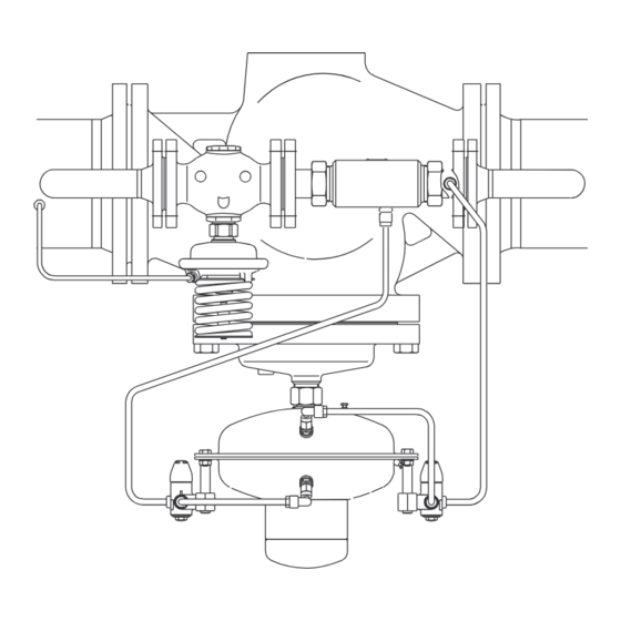
Page 8: Assembly Drawings, Dimensions
Pilot controller AVD Throttling element DN 25 SW 50 DN 25: pipe Ø 33,7 × 3,2 Material: ST 35.8 (not part of the delivery) these parts are not in the scope of delivery DN 100-125 8 | © Danfoss | 2016.05 VI.JA.C3.5B... - Page 9 No. 003G1599 these parts are not in the scope of delivery DN 40: pipe Ø 48,3 × 3,2 Material: ST 35.8 (not part of the delivery) DN 150-250 Dimensions Nominal diameter A ≥ © Danfoss | 2016.05 | 9 VI.JA.C3.5B...
-
Page 10: Start-Up
Pre-condition: Same pressure on both sides of the diaphragm. If the pressure load is one-sided, the (+)diaphragm chamber may have an excess pressure of 1 bar in comparison to the (-) diaphragm chamber. 10 | © Danfoss | 2016.05 VI.JA.C3.5B... -
Page 11: Adjustment Of The Setpoint
Value approx. 50 % of the max. flow rate 3. Regler PCVD 3. Adjustment of the pressure by turning the setpoint adjuster 4. Turning to the right, increases the setpoint. SW 22 Turning to the left, reduces the setpoint. © Danfoss | 2016.05 | 11 VI.JA.C3.5B... -
Page 12: Trouble Shooting
3. Replace actuator. The trim can be replaced by qualified personnel up to DN 125. From DN 150 replacement should be carried out by the Danfoss service personnel. 8.2 Diaphragm Break of the Controller SAVD If the control diaphragm 1 breaks, pressure is developped in the two intermediate chambers 2. -
Page 13: Replacement Of Valve, Actuator, Trim
1. Place actuator at the valve and push upwards. 2. Screw on union nut 2. 3. Align actuator, observe position of impulse tube connections. 4. Tighten union nut 1, max. torque 100 Nm. © Danfoss | 2016.05 | 13 VI.JA.C3.5B... -
Page 14: Replacement Of Trim Valve Vfg2
9.2 Replacement of Trim Valve VFG2 9.3 Dismounting, Mounting Actuator AVD, SAVD The trim can be replaced by qualified personnel up to DN 125. From DN 150 replacement should be carried out by the Danfoss service personnel. Removing the trim: Valves DN 100–125 SAVD Dismounting 1. -
Page 15: Replacement Of Trim Valve Avd, Savd
2. Unscrew trim 2. tighten with low torque, sealing is made with O rings. DN 25: with pipe tongs, wrap gum strips around the trim DN 40: with wrench SW 55 3. Pull out trim. © Danfoss | 2016.05 | 15 VI.JA.C3.5B... - Page 16 Antrieb SAVD ............26 Austausch von Ventil, Antrieb, Innengarnituren ..........27 Antrieb des Stellgeräts demontieren, montieren .......27 Austausch der Innengarnitur Ventil VFG 2 ............28 Demontage, Montage Antrieb AVD, SAVD ......28 Austausch der Innengarnitur Ventil AVD, SAVD ..........29 16 | © Danfoss | 2016.05 VI.JA.C3.5B...
-
Page 17: Sicherheitshinweise
Differenzdruckregelung von Wasser für Verwendung Heizung, Fernwärmeheizung und Kühlsysteme. Die zulässigen Mediumstemperaturen sind je nach Ausführung 5 - 150 °C, 5 - 200 °C. Die technischen Daten auf den Typenschildern sind für die Verwendung maßgebend. © Danfoss | 2016.05 | 17 VI.JA.C3.5B... -
Page 18: Beschreibung
über die Vorspannung der Sollwertfeder des Stellbereich. Pilotreglers. Das Stellgerät in der Hauptleitung ist drucklos geschlossen. Der Pilotregler in der Bypassleitung ist drucklos geöffnet. Technische Daten siehe Typenschilder und Technische Daten Datenblatt PCV. 18 | © Danfoss | 2016.05 VI.JA.C3.5B... -
Page 19: Lieferumfang
Cu-Rohr Ø 10 × 1 × 3000 mm DN 150-250 Bausatz Stellgerät PCV-VFG 2 Pilotregler AVD DN 40 SAVD Drosselelement Cu-Rohr Ø 6 × 1 × 1500 mm Cu-Rohr Ø 10 × 1 × 3000 mm © Danfoss | 2016.05 | 19 VI.JA.C3.5B... -
Page 20: Montage
• Belastung der Ventilgehäuse und des 6. Nochmals demontieren und und die Lage des Drosselelementes durch die Rohrleitungen Schneidrings überprüfen sind nicht zulässig. 6.5 Isolierung Bei Isoliermaßnahmen dürfen die Membranantriebe nicht isoliert werden. 20 | © Danfoss | 2016.05 VI.JA.C3.5B... -
Page 21: Einbauschemas
Hier sollte kein Absperrventil Drosselventil eingebaut (nur beiDN 150 - 250) werden, falls doch unbedingt gegen Pilotregler SAVD unbefugtes Schließen sichern CU-Rohr Ø 6 × 1 Steuerleitungen bei Montage verlegen Hilfsgesteuerters Sicherheitsabsperrventil PCVSAD © Danfoss | 2016.05 | 21 VI.JA.C3.5B... - Page 22 Bei Montage verlegen. Stellgerät PCV - VFG 2 Pilotregler AVD Drosselelement DN 25 SW 50 DN 25: Rohr Ø 33,7 × 3,2 Werkstoff: ST 35.8 (kein Lieferbestandteil) gestrichelt dargestellte Komponenten sind kein Lieferbestandteil DN 100-125 22 | © Danfoss | 2016.05 VI.JA.C3.5B...
-
Page 23: Abmessungen
CU-Rohr Ø 10 × 1 Montageset Bei Montage verlegen. Best. Nr. 003G1599 verwenden gestrichelt dargestellte Komponenten sind kein Lieferbestandteil DN 40: Rohr Ø 48,3 × 3,2 Werkstoff: ST 35.8 (kein Lieferbestandteil) DN 150-250 Abmessungen Nennweite A ≥ © Danfoss | 2016.05 | 23 VI.JA.C3.5B... -
Page 24: Inbetriebnahme
• Vor einer Dichtheitsprüfung bzw. Druckprüfung nach Abschnitt 7.3 vorgehen Voraussetzung: gleicher Druck auf beiden Seiten der Membrane. Bei einseitiger Druckbelastung ist in der (+) -Membrankammer ein max. Überdruck gegenüber der (-) -Membrankammer von 1 bar zulässig. 24 | © Danfoss | 2016.05 VI.JA.C3.5B... -
Page 25: Sollwerteinstellung
Anlage nach Abschnitt 7.4 durchführen. Bei Über- oder Unterschreitung den Druck nach Abschnitt 7.6 nachstellen. 2. Den Volumenstrom an einer Armatur 2 in Strömungsrichtung nach dem Regler PCVD einstellen: Wert ca. 50 % des max. Volumenstroms, siehe 3 Regler PCVD 3. -
Page 26: Störungshinweise
Sicherheitsmembrane 3 dadurch • wird das Ventil geschlossen • ist die Regelfunktion außer Betrieb • Anzeige des Membranbruchs durch geringen Wasseraustritt an der Verschraubung 4 Der Regler muss nach einem Membranbruch ausgetauscht werden. Pilotregler SAVD 26 | © Danfoss | 2016.05 VI.JA.C3.5B... -
Page 27: Austausch Von Ventil, Antrieb, Innengarnituren
4. Überwurfmutter 1 anziehen, Anzugsmoment Montage 100 Nm 1. Antrieb am Ventil ansetzen und hochdrücken 2. Überwurfmutter 2 aufschrauben 3. Antrieb ausrichten, Position der Steuerleitungsanschlüsse beachten 4. Überwurfmutter 1 anziehen, max. Anzugsmoment 100 Nm © Danfoss | 2016.05 | 27 VI.JA.C3.5B... -
Page 28: Austausch Der Innengarnitur Ventil Vfg2
9.2 Austausch der Innengarnitur Ventil VFG2 9.3 Demontage, Montage Antrieb AVD, SAVD Der Austausch der Innengarnitur bis DN 125 ist durch sachkundige Personen möglich. Ab DN 150 sollte der Austausch durch den Danfoss- Kundendienst erfolgen. Innengarnitur ausbauen Ventile DN 100–125... -
Page 29: Austausch Der Innengarnitur
2. Innengarnitur 2 herausschrauben Reihenfolge. Die Innengarnitur nur mit niedrigem Anzugsmoment anziehen, DN 25: mit Rohrzange, Gummistreifen um Abdichtung erfolgt mit O-Ringen. Innengarnitur wickeln DN 40: mit Schlüssel SW 55 3. Innengarnitur herausziehen © Danfoss | 2016.05 | 29 VI.JA.C3.5B... - Page 30 Instructions PCVD, PCVSAD 30 | © Danfoss | 2016.05 VI.JA.C3.5B...
- Page 31 Instructions PCVD, PCVSAD © Danfoss | 2016.05 | 31 VI.JA.C3.5B...
- Page 32 PCVD, PCVSAD Danfoss can accept no responsibility for possible errors in catalogues, brochures and other printed material. Danfoss reserves the right to alter its products without notice. This also applies to products already on order provided that such alterations can be made without subsequential changes being necessary eady agreed.