Table of Contents
Advertisement
Quick Links
INSTRUCTIONS-PARTS LIST
This manual contains important
warnings and information.
READ AND KEEP FOR REFERENCE.
INSTRUCTIONS
STAINLESS STEEL
Dura-Flo
With Severe-Duty Rod and Cylinder
Part No. 237–516 Pump, Series A,
21:1 Ratio, with Bulldog Air Motor
145 bar (2100 psi) Maximum Fluid Working Pressure
7 bar (100 psi) Maximum Air Input Pressure
Part No. 237–517 Pump, Series A,
13:1 Ratio, with Senator Air Motor
90 bar (1300 psi) Maximum Fluid Working Pressure
7 bar (100 psi) Maximum Air Input Pressure
Refer to page 2 for Table of Contents.
GRACO INC. P.O. BOX 1441 MINNEAPOLIS, MN 55440–1441
1200 Pumps
COPYRIGHT 1995, GRACO INC.
308–360
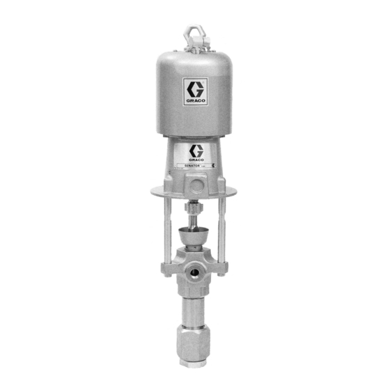
Model 237–516
Model 237–517
04140
Rev. A
04143
Advertisement
Table of Contents

Related Manuals for Graco Dura-Flo A Series


Summary of Contents for Graco Dura-Flo A Series
- Page 1 90 bar (1300 psi) Maximum Fluid Working Pressure 7 bar (100 psi) Maximum Air Input Pressure Refer to page 2 for Table of Contents. 04143 Model 237–517 04140 GRACO INC. P.O. BOX 1441 MINNEAPOLIS, MN 55440–1441 COPYRIGHT 1995, GRACO INC.
- Page 2 This equipment is for professional use only. Read all instruction manuals, tags, and labels before operating the equipment. Use the equipment only for its intended purpose. If you are not sure, call Graco Technical Assis- tance at 1–800–543–0339. Do not alter or modify this equipment.
- Page 3 WARNING INJECTION HAZARD Spray from the gun, leaks or ruptured components can inject fluid into your body and cause extremely serious injury, including the need for amputation. Fluid splashed in the eyes or on the skin can also cause serious injury. Fluid injected into the skin might look like just a cut, but it is a serious injury.
-
Page 4: Fire And Explosion Hazard
WARNING FIRE AND EXPLOSION HAZARD Improper grounding, poor ventilation, open flames or sparks can cause a hazardous condition and re- sult in a fire or explosion and serious injury. Ground the equipment and the object being sprayed. Refer to Grounding on page 5. If there is any static sparking or you feel an electric shock while using this equipment, stop spray- ing immediately. -
Page 5: General Information
4. Spray gun: ground through connection to a prop- parts drawing. erly grounded fluid hose and pump. NOTE: Always use Genuine Graco Parts and Acces- 5. Fluid supply container: follow your local code. sories, available from your Graco distributor. Refer to Product Data Sheet, Form No. - Page 6 Installation System Accessories (continued) A pump runaway valve (C) senses when the pump is running too fast and automatically shuts off the air to the motor. A pump which runs too fast WARNING can be seriously damaged. An air manifold (G) has a 3/4 npsm(f) swivel air A bleed-type master air valve (E) and a fluid drain inlet.
-
Page 7: Typical Installation
Installation TYPICAL INSTALLATION Pump Electrically Conductive Air Supply Hose Fluid Whip Hose Wall Bracket Air Line Filter Gun Swivel Pump Runaway Valve Bleed-Type Master Air Valve Airless Spray Gun Air Line Lubricator (for accessories) Suction Kit Bleed-Type Master Air Valve Fluid Filter Ground Wire and Clamp (required, for pump) - Page 8 Operation/Maintenance Pressure Relief Procedure Packing Nut/Wet-Cup Before starting, fill the packing nut (2) 1/3 full with Graco Throat Seal Liquid (TSL) or compatible solvent. WARNING See Fig. 3. INJECTION HAZARD The system pressure must be manually WARNING relieved to prevent the system from starting or spraying accidentally.
- Page 9 Operation/Maintenance Flush the Pump Before First Use NOTE: When changing fluid containers with the hose and gun already primed, open the drain valve (M) to The pump is tested with lightweight oil, which is left in help prime the pump and vent air before it enters the to protect the pump parts.
-
Page 10: Shutdown And Care Of The Pump
Operation/Maintenance Shutdown and Care of the Pump Flush with a fluid that is compatible with the fluid you are pumping and with the wetted parts in your system. Check with your fluid manufacturer or supplier for rec- WARNING ommended flushing fluids and flushing frequency. Al- ways flush the pump before fluid dries on the displace- To reduce the risk of serious injury whenever you ment rod. -
Page 11: Troubleshooting Chart
Turn on the air just enough to start the pump. If the pump starts when the air is turned on, the obstruction is in the fluid hose or gun. NOTE: If you experience air motor icing, call Graco Technical Assistance (1–800–543–0339). -
Page 12: Required Tools
5. Reconnect all hoses. Reconnect the ground wire if CAUTION it was disconnected. Fill the packing nut (2) 1/3 full of Graco Throat Seal Liquid or compatible solvent. Be sure to use at least two people when lifting, mov- ing, or disconnecting the pump. This pump is too 6. - Page 13 Service Model 237–516 Shown Torque to 136–149 N.m (100–110 ft-lb) Torque to 196–210 N.m (145–155 ft-lb) Torque to 81–89 N.m (60–66 ft-lb) Fig. 4...
-
Page 14: Displacement Pump Service
Service DISPLACEMENT PUMP SERVICE If the assembly separates at joint B: Disassembly a. Unscrew the cylinder (9) and valve housing (18) from the outlet housing (7). Gently pull the When disassembling the pump, lay out all the removed cylinder and valve housing straight out of the parts in sequence, to ease reassembly. - Page 15 Service Torque to 325–353 N.m (240–260 ft-lb). Lubricate. Torque to 190–217 N.m (140–160 ft-lb). 03794A Fig. 5 03793A Torque to 386–407 N.m (285–300 ft-lb). Fig. 6...
- Page 16 Service Reassembly 6. Lubricate the piston packings. Slide the displace- ment rod (1) and piston assembly down into the cylinder (9). The cylinder is symmetrical, so either 1. If it was necessary to remove the piston ball hous - end may face up. Use a rubber mallet to drive the ing (10) from the displacement rod (1), clean the rod into the cylinder, until the piston seat housing threads of the rod and the ball housing.
- Page 17 Service Torque to 136–149 N.m (100–110 ft-lb). Torque to 325–353 N.m (240–260 ft-lb). Torque to 386–407 N.m (285–300 ft-lb). Lubricate. Lips face up. Lips face down. See Throat Packing Detail at left. See Piston Packing Detail at left. Torque to 190–217 N.m (140–160 ft-lb). Throat Packing Stack Detail (Displacement Pump 237–515 Shown;...
- Page 18 Parts Part No. 237–516 Pump, Series A Part No. 237–517 Pump, Series A 21:1 Ratio, with Bulldog Air Motor 13:1 Ratio, with Senator Air Motor These parts are included in These parts are included in Connection Kit 235–417. Connection Kit 235–417. For applications requiring For applications requiring stainless steel tie rods, order...
- Page 19 Parts NOTE: The parts listed on this page are common to all dis- Part placement pumps covered in this manual. Refer to page 20 Description for the different packing configurations available. 184–487 ROD, displacement; stainless steel 236–582 PACKING NUT; stainless steel * These parts are included in Repair Kit 237–178, which 237–186 HOUSING, outlet;...
-
Page 20: Packing Kits
Packing Kits Leather Packing Kit 237–178, for Standard Displacement Pump 237–514, Series A Part THROAT PACKINGS: PISTON PACKINGS: LIPS FACE DOWN LIPS FACE UP Description 184–309 V-PACKING, throat; leather 184–179 GLAND, throat, female; stainless steel 1 109–309 V-PACKING, throat; Teflon 184–229 GLAND, throat, male;... -
Page 21: Technical Data
Technical Data (Model 237–516 Bulldog Pump) WARNING Be sure that all fluids and solvents used are chemically compatible with the Wetted Parts listed below. Always read the manufacturer’s literature before us- ing fluid or solvent in this pump. Ratio ............... 21:1 Maximum fluid working pressure . - Page 22 Technical Data (Model 237–517 Senator Pump) WARNING Be sure that all fluids and solvents used are chemically compatible with the Wetted Parts listed below. Always read the manufacturer’s literature before us- ing fluid or solvent in this pump. Ratio ............... 13:1 Maximum fluid working pressure .
- Page 23 Dimensions Mounting Hole Layout Model 237–516 Shown 94.28 mm (3.712”) 101.6 mm (4.0”) 94.28 mm (3.712”) 50.8 mm (2.0”) Three M16 x Holes 11.1 mm (0.437”) 88 mm DIA (4) (3.464”) 0653 04143 Pump Model 237–516 1134 mm 590 mm 544 mm 257 mm 2 in.
-
Page 24: Warranty
Graco distributor to the original purchaser for use. As purchaser’s sole remedy for breach of this warranty, Graco will, for a period of twelve months from the date of sale, repair or replace any part of the equipment proven defec- tive.