
Related Manuals for Murray MYZ4219000


Summary of Contents for Murray MYZ4219000
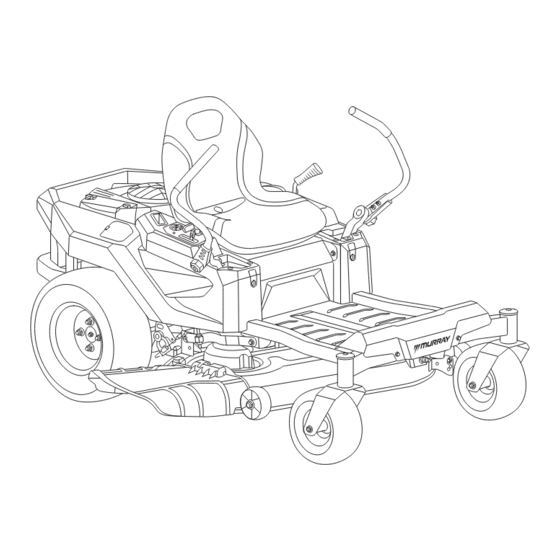
- Page 1 ZERO TURN LAWN MOWER Operator’s Manual Model #MYZ4219000 Customer Service Number: 855-693-2582 | www.murray.com...
-
Page 2: Table Of Contents
TABLE OF CONTENTS General Information General Information ........3 Maintenance...........31 Reference Environmental Disposal SECTION 1 SECTION 6 ........32 Operator Safety........4 Cleaning the Mower All references in this manual to the left side or right side SECTION 2 and front or back of the machine are from the operator’s position. -
Page 3: Operator Safety
Operator Safety Slope Identification Guide WARNING: Do not operate on slopes greater than 15 degrees. Save These Instructions Safety Alert Symbol and 1. Use a straight edge at least two (2) feet long (A, Fig. 1). Signal Words A 2x4 or a straight piece of metal works as well. Save these instructions for future reference. -
Page 4: Safety Decals
Safety Instructions Safety Decals • Keep the area of operation clear of all bystanders, particularly small children. Stop the machine and attachment(s) if anyone enters the area. The following safety symbols appear on this product. Before you operate the mower, please study them and learn their meaning. •... - Page 5 • Stop the blade(s) when crossing gravel drives, walks, or Slope Specific Hauling • To avoid serious injury or death, do not modify engine in roads, and while not cutting grass. any way. Tampering with the governor setting can lead to a runaway engine and cause it to operate at unsafe •...
-
Page 6: Assembly Instructions
Assembly Instructions Assemble the Seat 1. Align the two threaded holes on the bottom of the seat with the two eyelet slots on the seat pan. Slide the seat SCarefully remove the product and any accessories from the downward to secure it. package. -
Page 7: Assemble Drive Control Lever
Assemble Drive Control To adjust the height of the lever: To adjust levers forward/rearward: Lever 1. Remove the two bolts and two lock nuts that secure the The drive control levers are designed to be adjustable. drive control lever to the upper handle adjuster. Adjust them to a comfortable position for you before operation. -
Page 8: Install Hitch
Install Hitch Connecting the Battery Check/Adjust the Tire Pressure To tow objects or install the grass catcher, locate the hitch The battery is located under the operator’s seat. To connect and install it on the rear of the frame using two bolts and the battery cables, proceed as follows: nuts. -
Page 9: Features And Controls
Features and Controls Ignition switch Drive control lever The following control symbols appear on this product. Before you operate the mower, please study them and learn their meaning. Storage compartment Symbol Explanation Cup holder Deck lift handle Choke Throttle/Choke Control Lever FAST throttle position PTO knob SLOW throttle position... -
Page 10: Operating The Mower
Operating the Mower 4. Ignition Switch 6. Cup Holder The cup holder is located on the rear of the left console. The ignition switch has three positions: Read the Operation Instruction section before you operate Give yourself a minimum of two mower widths of 7. -
Page 11: Safety Interlock System Tests
Safety Interlock System Engine Fuel Recommendations If the oil level is FULL, install and tighten the dipstick. • If the oil level is LOW, add oil into the oil fill tube. (Fig. 12) Tests • Check and Add Engine Oil Fuel must meet these requirements: Wait one minute and check the oil level again. -
Page 12: Operation Instructions
Operation Instructions Using the Throttle/Choke Stop the Engine When Adding Fuel Lever Stop the engine and let it cool for at least 3 minutes • before you remove the fuel cap. Start the Engine The throttle/choke lever is located on the right panel. When Extinguish all cigarettes, cigars, pipes, and other •... -
Page 13: Driving The Mower
Driving the Mower Driving the Mower Forward: 1. From the neutral position, slowly and evenly move both drive control levers forward. The mower will start to move forward. 2. As the drive control levers are pushed farther forward the speed of the mower will increase. NOTICE: This mower is not equipped with a gas pedal. -
Page 14: Adjusting The Mower Cutting Height
Adjusting the Mower Adjusting Deck Anti-scalp Cutting Height Wheel NOTICE: The bottom of the deck anti-scalp wheels CAUTION: Stop the mower and disengage blades should be positioned approximately 1/8 in. - 1/2 in. before adjusting the cutting height of the deck. off the ground when the mower is at the desired cutting The deck adjusting lever is located on the mower’s left height. -
Page 15: Mowing
Mowing Engaging the PTO Mowing Tips Engaging the PTO transfers power to the cutting deck to enter mowing mode. To engage the PTO: WARNING: To help avoid blade contact or a thrown 1. Move the throttle to the FAST position. object injury, keep bystanders, helpers, children, and pets DANGER: This machine away from the machine while it is in operation. -
Page 16: Maintenance
Maintenance • The speed of the mower will affect the quality of the When stopping the mower for any reason while on a grass mower cut. Mowing at full speed will adversely affect surface, always: the cut quality. Control the ground speed with the drive control levers. -
Page 17: Cleaning The Mower
Cleaning the Mower Deck 8. Stop the engine. Cleaning the Mower ENGINE 9. Turn OFF the water supply. First 5 Hours 10. Remove the garden hose and quick disconnect from the Change the engine oil. NOTICE: The mower ONLY comes with a washout port washout port. -
Page 18: Leveling The Cutting Deck
Removing the Cutting Deck Leveling the Cutting Deck If your lawn appears unevenly cut after using the mower, the cutting deck may need adjusting. Before deciding that leveling the cutting deck is necessary, make sure the tires DANGER: Mower blades are sharp. Wrap the are properly inflated to the recommended psi when blade(s) or wear gloves, and use extra caution when mowing. -
Page 19: Changing The Deck Belt
Changing the Deck Belt Changing the Drive Belt WARNING: Stop the engine, engage the parking WARNING: Stop the engine, engage the parking brake, and remove the key. brake, and remove the key. WARNING: Belts on your mower are subject to wear WARNING: To change the drive belt, raise the and should be replaced if any signs of wear are present. -
Page 20: Replacing The Cutting Blades
Replacing the Cutting Blades 5. Remove the blade nut and blade. (Fig.28) Sharpening the Blade 6. When replacing or re-installing the blade, be sure to install the blade on the side with its stamped part 1. To properly sharpen the cutting blades, remove equal number facing the ground (the same direction as amounts of metal from both ends of the blades along the working blades). -
Page 21: Checking The Tire Pressure
Checking the Tire Pressure Battery Maintenance Replacing the Battery; Cleaning the Battery and Battery Cables For the correct traction and the best mowing performance, make sure that the front tires are inflated to 20 psi and the WARNING: Always shield eyes and protect skin rear tires inflated to 14 psi. -
Page 22: Checking The Engine Oil Level
Checking the Mower Blade Changing the Engine Oil Changing the Air Filter Checking the Engine Stop Time and Oil Filter Oil Level 1. Remove the dipstick. Wipe the dipstick clean of WARNING: DO NOT start or operate the engine remaining oil. without an air filter as it is a fire hazard. -
Page 23: Checking The Spark Plug
Checking the Spark Plug Pushing the Mower By Towing with the Mower Checking the Spark Plug Gap Hand Use a spark plug feeler gauge (A) to check the gap between the two electrodes. When the gap is correct, the gauge will •... -
Page 24: Transport
Transport Storage Empty the fuel tank with a suction pump before transport- • Use extra care when loading or unloading the machine Fuel System ing the machine. Start the engine and let it run until it has into a trailer or truck. This machine should not be driven used up all remaining gasoline. -
Page 25: Troubleshooting
Troubleshooting The engine runs, but the mower The transmission is in neutral. Move the drive control levers into the will not drive. forward gear. The bypass valve is in the open position. Close bypass valve. When the control lever is in neutral state, Check if the hydraulic bridge tension the hydraulic bridge parking gear plate spring has fallen off. -
Page 26: Specifications
Rear Tire Size 20 in. x 10.0 in. – 10.0 in. Specifications Chart Front Tire Pressure 20 psi Rear Tire Pressure 14 psi MOWER MODEL MYZ4219000 Turning Radius 0 in. Engine Electrical System Model Briggs & Stratton EX1900 Fuse 20 Amp... -
Page 27: Power Ratings Disclaimer
Disposal Power Ratings Disclaimer Power Ratings: The gross power rating for individual gasoline engine models is labeled in accordance with SAE (Society of Automotive Engineers) code J1940 Small Engine Power & Torque Rating Procedure, and is rated in accordance with SAE J1995. •... -
Page 28: Warranty
(3) Normal maintenance parts and service; (4) If used for racing or any other competitive activity. E. SECURING WARRANTY SERVICE: To secure warranty service, the purchaser must (1) Report the product defect to the Murray customer care line at 855-693-2582 and request repair within the applicable warranty term, (2) Present evidence of the warranty start date, and (3) Make the Equipment available to an authorized service center within a reasonable period of time.