Table of Contents
Advertisement
Owner's Manual
10 in.
TABLE SAW
Model No.
315.228110
Save this manual for
future reference.
_,
CAUTION:
Read and follow all
Safety Rules and Operating
Instructions before first use of this
product.
Customer
Help Line: 1-800-932-3188
Sears,
Roebuck
and Co.,
Hoffman
Estates,
IL 60179
USA
visit
the Craftsman
web page:
www.sears.com/craftsman
972000-713
1-00
• Safety
• Features
• Assembly
• Operation
• Maintenance
• Parts List
®
Advertisement
Table of Contents

Related Manuals for Craftsman 10 IN. TABLE SAW 315.22811


Summary of Contents for Craftsman 10 IN. TABLE SAW 315.22811
- Page 1 Read and follow all Safety Rules and Operating Instructions before first use of this product. Customer Help Line: 1-800-932-3188 Sears, Roebuck and Co., visit the Craftsman web page: 972000-713 1-00 Hoffman Estates, IL 60179 www.sears.com/craftsman • Safety • Features • Assembly •...
- Page 2 Carefully read through this entire owner's manual before using your new saw. Pay close attention to the Rules For Safe Operation, and all Safety Alert Symbols, including Danger, Warning and Caution. If you use your saw properly and only for what it is intended, you will enjoy years of safe, reliable service.
- Page 3 C.Blade Check andBlade Guard Assembly ..To Check Saw Blade Installation ... To Install Blade Guard ... • Operation A. General Information Grounding Types Of Cuts ... Cutting Tips ... B. Settings and Adjustments To Remove The Blade ...
- Page 4 READ ALL INSTRUCTIONS KNOW YOUR POWER TOOL. Read the owner's manual carefully. Learn the saw's applications and limitations as well as the specific potentia_ hazards related to this tool. DO NOT USE IN DANGEROUS ENVIRON- MENT.
-
Page 5: Rules For Safe Operation
Check alignment of moving parts, binding of moving parts, breakage of parts, saw stability, mounting and any other conditionsthat may affect its operation. A damaged part must be... - Page 6 USE A SUPPORT FOR THE SIDES AND BACK .OF THE SAW TABLE when sawing wide or long workpieces. Use a sturdy "outrigger" support if a table extension is more than 24 inches long and is attached to the saw, to prevent tipping.
- Page 7 ELECTRICAL CONNECTION Your Sears Craftsman Table Saw is powered by a precision built electric motor. It should be connected to a power supply that is 120 volts, 60 Hz, AC only (normal household current). Do not operate this tool on direct current (DC).
- Page 8 Also, the workpiece area which will be or has been cut by the blade. The distance that the tip of the saw blade tooth is bent (or set) outward from the face of the blade.
- Page 9 Sears. If any parts are missing, do not attempt to assemble your table saw, plug in the power cord, or turn the switch on until the missing parts are obtained and are installed The following recommended accessories are currently available at Sears Retail Stores.
-
Page 10: Table Of Contents
The following items are included with your Table Saw. A. Storage Bracket B. Screw (1/4-20 x 1/2 in. Pan Hd.) ... C. Lower Brace ... D. Hex Nut (5/16-18) ... E. Washer (5/16 in.} ... E Leveling Foot ... G, Leg ... - Page 11 The following items are included with your Table Saw. N. Front Rail ... O. Miter Fence Holder With Adjusting Clamp ... 1 P. Miter Fence With Miter Indicator ... 1 Q. Screw ... R. Rip Scale Indicator ... 1 S. Hex Nut ...
- Page 12 COMBINATION SQUARE 1/8in. HEXKEY._--__ 3/32in,HEXKEY_ CRRFTSMRN"TABLESAW315.228110 and alignment. Note: The four hex keys listed below have been tools are typical shop tools and are not included with your saw. 'U'l'O'l'l'l'l'l,U,l,l,l,l,t, .t.l,',l,*.l.,.l,L,J.l,l.,.I,*,l.*,l,,,I.,,I,_.l.,,I.i ADJUSTABLE WRENCH SCREWDRIVER #2 PHILLIPS 3/'16in. HEXKEY,---,_-,_,_ 5/32in. HEXKEY._.._-_._._ FRAMING SQUARE ,_rl,g,f,v,l,l,l,l,l,l,l,U,l,f.
- Page 13 The accessory table can be moved from the right side of the saw to the left side as needed. The rip fence is used to position work that will be cut lengthwise. scale on the front rail shows the distance between rip fence and the blade.
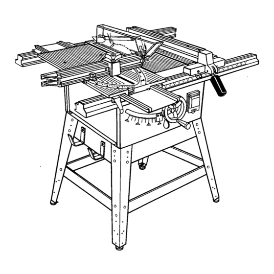
- Page 14 MITER TABLE THROAT PLATE ADJUST CLAMP MITER FENCE QUICK-STOP END CAP MITER FENCEHOLDER STORAGE BRACKETS) LOCKING CLAMPS LEGSTAND LEVELING FOOl CRAFTSMAN"TABLESAW315,228110 SAW BLADE RIVING KNIFE MITER SCALE MITER TABLE BASE REAR RAIL RIP FENCE ACCESSORY TABLE FRONT RAIL HANDLE NITH LOCKABLECOVER BLADE...
- Page 15 See Figure 7. For maximum performance, it is recommended you use the Craftsman 40 tooth, 10 inch carbide tipped combination blade provided with your saw. It is a high-quality carbide tipped combination blade suitable for ripping and crosscut operations. Other...
-
Page 16: Carriage Bolt (5/16-18 X 3/4 In.)
Assembly is best done in the area where the saw will be used. When you remove the table saw base, loose parts, and hardware from the packing materials, check all items with the loose parts list and drawing. If you are unsure about the description of any part, refer to the drawing. -
Page 17: Storage Bracket
Fences procedure. The bench surface must have an opening for sawdust to fall through, as large as the opening in the bottom of the saw base. A height ot 36 in. from the top of the saw table to the floor is recommended. MOUNTING... -
Page 18: To Install Front And Back Rail
Note: Hole "A" should be used fo,_short pieces of wood and hole "B" shouSdbe used for Songpieces of wood. • Adjust the miter indicator to the scale. • Retighten the adjusting clamp. CRAFTSMAN"TABLESAW315.228110 LOCKING will securely FRONT RAIL CLAMP HOLDER NUT REAR... -
Page 19: To Check Saw Blade Installation
BLADE GUARD ASSEMBLY TO CHECK SAW BLADE INSTALLATION • To check the saw blade, first remove the three screws holding the throat plate in place. Remove the throat plate. See Figure 17. • Make sure the bevel locking lever is securely pushed to the left. -
Page 20: To Install Blade Guard
5 as needed. Tighten attachment nuts securely. If riving knife is not positioned correctly, with blade up, it could contact saw table when blade is lowered and restrict blade elevation. [] Blade alignment with the riving knife can be adiusted for different blade widths. -
Page 21: A. General Information
A. GENERAL INFORMATION GROUNDING Your saw's three-prong plug must be plugged into a matching outlet that is properly installed and grounded in accordance with all local codes and ordinances. "Improper connection of the equipment can result in electric shock. Check with an electrician or service personnel if you are unsure about proper grounding. - Page 22 Knock out any loose knots with a hammer before making the cut. • Always provide proper support for the wood as it comes out of the saw. • See the Accessories Section in this manual for a list of recommended blades.
-
Page 23: B. Settings And Adjustments
B. SETTINGS AND ADJUSTMENTS TO REMOVE THE BLADE Use the two wrenches supplied with the saw for this procedure WARNING: Unplug your saw and make sure the blade guard assembly is installed working properly to avoid serious personal • Raise the blade guard. See figure 27, overview of •... -
Page 24: Remove The Throat Plate
• Put the saw in Angle mode by moving the bevel locking lever to the right. Slowly turn the blade adjusting handle until the bevel indicator is at a 30 degree angle. -
Page 25: To Avoid Kickback
Kickback can occur when the blade stalls or binds, kicking the workpiece back toward you with great force and speed. If your hands are near the saw blade, they may be jerked loose and thrown into the blade. Obviously, kickback can cause serious injury, and it is weUworth using precautions to avoid the risks. -
Page 26: To Make A Push Stick
HOW TO MAKE A FEATHERBOARD The featherboard is an excellent project for your saw. Select a solid piece of lumber approximately 3/4 in. thick, 3-5/8 in. wide and 18 inches long. Mark the center of the width on one end of the stock. Miter one-half of the width to 30 °... -
Page 27: To Set The Scale To The Blade
1/8 in. to 1/4 in. but the lowest points (gullets) are below the top surface. See Figure 36. WARNING: Unplug the saw and make sure the blade guard assembly is installed properly to avoid serious personal injury. • Push the bevel locking lever to the left for elevation mode. -
Page 28: To Lock Miter Table
The miter slide lock is placed in a slot on the base to align the miter table with the front edge of the saw table. The sliding miter table should be locked for any cut in which the operator prefers a fixed table. - Page 29 • To turn saw Off, (A) press or push outside of switch cover, or (B) lift switch cover and press switch button. See Figure 41. Note: To prevent unauthorized use, lock your saw in the Off position with a padlock figure 41.
-
Page 30: To Make A Bevel Cross Cut
• Place a support (the same height as saw table) behind the saw for the cut work, • Make sure the wood is clear of the blade before turning on the saw. - Page 31 Position the rip fence the desired blade for the cut and lock securely. • Place a support (the same height as saw table) behind the saw for the cut work. See Quick Fold Table in Accessories on page 9. •...
- Page 32 • Put the saw in Angle mode by pushing the bevel locking lever to the right. Turn the blade adjusting handle until the blade indicator shows a 30 degree angle. Push the bevel locking lever securely to the left to lock the angle.
-
Page 33: To Make Dado Cuts
• Unplug your saw. _k, WARNING: Unplug the saw to avoid possible mjury. • Remove the riving knife and guard assembly. Figure 19, on page 20. • Retighten the two hex nuts on base assembly. -
Page 34: Maintenance
Always begin by disconnecting the power supply. TO SET BLADE AT 0 OR 45 DEGREES The angle settings of your saw have been set at the factory and, unless damaged in shipping, should not require setting during assembly. After extensive use, it may need to be checked. - Page 35 Make two or three test cuts on scrap wood. If the cuts are not true, repeat the process. WARNING: Before plugging the saw back in to make test cuts, make sure the switch is in the Off position and the blade guard is in place.
-
Page 36: To Adjust The Front And Rear Rail Clamps
Remove the front and rear rails by loosening the rail clamps and sliding the rails off. • Rotate each rail clamp to the left until it hits or comes in contact with the bottom of the saw table. • _ghtan rail holder nut until it is snug. •... -
Page 37: Sliding Miter Table Assembly
The sliding miter table assembly has been preset at the factory to be parallel to the blade. However, misalignment during shipping or requirements realignment. The square relationship distance from the front to the rear of the miter table base during a cut is very important precise and accurate cuts. -
Page 38: To Check Miter Base Parallelism
• Set saw up as if you were preparing to make a cut. Tighten rail clamps, miter _ocking clamps, ad}usting clamp, etc. • Slide miter table (A) to the front of miter base (B) as far as it will go. Place a reference mark (C) near the end of the miter table as shown in figure 54. -
Page 39: To Check Miter Fence Alignment
TO CHECK MITER FENCE ALIGNMENT The miter fence must be perpendicular when set at zero degrees. • Set the miter fence (H) at 0 ° as shown in figure 56. Miter indicator (I) should be set precisely secured in place with adjusting Note: The quick-stop is not necessary checking... -
Page 40: To Adjust The Miter Fence
TO ADJUST THE MITER FENCE • Set the miter fence (H) at 0 ° as shown in figure 56. Miter indicator (I) should be set precisely on 0 ° and secured in place with adjusting clamp (J). • There are four slides located under the sliding miter table. - Page 41 Retighten hex nut, securing eccentric screw and quick-stop. • Check your work. If the quick-stop is not at zero degrees, repeat steps 1-4. M_ERINDICATOR MITER FENCE ZERO ADJUSTING CLAMP DEGREE MITER FENCE QUICK STOP AND ECCENTRIC SCREW CRAFTSMAN" TABLE SAW 315.228110 Figure 60...
-
Page 42: Locker Bracket Assembly
This saw has been lubricated at the factory prior to shipment. Following extended use, you should inspect and lubricate the following areas to assure smooth operation. LOCKER BRACKET ASSEMBLY See Figure 61. • Add dry lube between both bevel gears, the backup washers and the locker bracket. - Page 43 rlIAFTSMAW TABLESAW315.228110...
- Page 44 CRAFTSNAN"TABLESAW315.228110 Cause Blade is out of balance. Blade is damaged. Saw is not mounted securely, Work surface is uneven. Blade is warped Rip fence not mounted correctly. Rails are dirty or sticky. Clamp screw is out of adjustment.
- Page 45 [ Problem Saw does not make accurate 90 or 45 degree cuts. Blade adjusting handle is hard to turn. Saw does not start. Blade makes poor cuts. Blade does not lower when turning blade adjusting handle, Motor labors in rip cut.
- Page 46 FORMITER TABLEASSEMBLY, REFER TO FIGURE B FORMOTOR ASSEMBLY, REFER TO NOTE"A",PAGE48 CRAFTSMAN 10 in. TABLE SAW - MODEL FIGURE A: 10 in. TABLE SAW FORBLADE GUARD ASSEMBLY, REFER TOFIGURE D NO. 315.228110 FORRIPFENCE ASSEMBLY, FORLEGSTAND ASSEMBLY, REFER TO FIGURE C...
- Page 47 969222-001 Spring ... 1 969221-001 Spring ... 1 Washer ... 1 706382-359 Washer ... 3 706382-360 10 in. TABLE SAW - MODEL NO. 315.228110 PARTS LIST - FIGURE A regarding your TABLE SAW or when ordering Part Quart. Number 706382-346...
- Page 48 Center. Contact your nearest Sears Retail Store for Service Center information. possibly causing electrical shock or electrocution. Any repairs requiring disassembly of your table saw requires safety testing to be performed by your nearest Sears Repair Center. Contact your nearest Sears Retail Store for Service...
- Page 49 CRAFTSMAN FIGURE 29" Key Part Number Description 969177-004 Miter Table Top ... 969188-001 Miter Fence ... 661811-001 Pivot ... 969190-001 Saw Gage ... 969191-001 Miter indicator 969192-001 Fence Holder ... **STD523132 *Bolt (5/16-18 x 3-1/4 in. Hex Hd.)... 1 661797-002 Warning Label ...
- Page 50 969156-001 Rod ... 610878-003 *Screw (1/4-20 x 5/8 in. Button Hd.) ... * Standard Hardware Item -- May Be Purchased Locally CRAFTSMAN" T ABLE SAW 315.228110 10 in. TABLE SAW - MODEL FIGURE C: RIP FENCE ASSEMBLY Key Part Quan.
- Page 51 CRAFTSMAN FIGURE *Standard *Standard 10 in. TABLE SAW - MODEL D: BLADE GUARD ASSEMBLY Part Number 968700-004 969169-001 662002-001 969608-001 969233-010 969170-001 969610-002 969612-001 969170-002 969168-008 12 980400-001 13 980324-001 Hardware Item -- May Be Purchased FIGURE E: REPLACEMENT PARTS Key Part No.
- Page 52 TABLE SAW or when ordering repair parts. The model number will be found on a plate attached to the side panel of the cabinet. Always mention the model number in all correspondence FIGUREF CRAFTSMAN 10 in. TABLE SAW- MODEL NO.
- Page 53 * Bolt (1/4-20 x 3/4 in. Hex Hd.) ... ** STD522507 Owner's Manual 972000-713 10 in. TABLE SAW - MODEL NO. 315.228110 to the side panel of the cabinet. Always PARTS LIST FOR FIGURE Standard Hardware Item -- May Be Purchased Locally Available From Div.
- Page 54 In U.S.A. or Canada for in-home major brand repair service: Call 24 hours a day," 7 days a week 1-800-4-MY-HOME Para pedir servicio de reparacibn Au Canada pour tout le service ou les pieces - 1-800-469 For the repair or replacement Call 6 a.m.