Table of Contents
Advertisement
Owner's Manual
10 in.
TABLE SAW
Model No.
315.228110
Save this manual for
future reference.
CAUTION:
Read and follow all
Safety Rules and Operating
Instructions before first use of this
product.
Customer Help Line: 1-800-932-3188
Sears, Roebuck and Co., Hoffman Estates, IL 60179 USA
Visit the Craftsman web page: www.sears.com/craftsman
972000-713
4-11-06 (Rev:00)
1
• Safety
• Features
• Assembly
• Operation
• Maintenance
• Parts List
®
TABLE SAW 315.228110
R
Advertisement
Table of Contents
Troubleshooting

Related Manuals for Craftsman 315.228110


Summary of Contents for Craftsman 315.228110
-
Page 1: Table Saw
Instructions before first use of this • Operation product. • Maintenance Customer Help Line: 1-800-932-3188 • Parts List Sears, Roebuck and Co., Hoffman Estates, IL 60179 USA Visit the Craftsman web page: www.sears.com/craftsman 972000-713 4-11-06 (Rev:00) ® TABLE SAW 315.228110... -
Page 2: Table Of Contents
WARRANTY FULL ONE YEAR WARRANTY ON CRAFTSMAN TABLE SAW If this Table Saw fails due to a defect in material or workmanship within one year from the date of purchase, Sears will repair it, free of charge. Contact a Sears Service Center for repair. -
Page 3: Table Of Contents
To Adjust Quick Stop ..........................41 Lubrication ..............................42 Locker Bracket Assembly ..........................42 Tilt / Elevating Mechanism ........................... 42 Troubleshooting ............................ 44-45 Exploded View and Repair Parts List ....................46-53 Parts Ordering / Service .......................back page ® TABLE SAW 315.228110... -
Page 4: Rules For Safe Operation
NEVER STAND ON TOOL. Serious injury could DO NOT leave tools or pieces of wood on the occur if the tool is tipped or if the blade is unin- saw while it is in operation. tentionally contacted. ® TABLE SAW 315.228110... - Page 5 When servicing, use only identical loss of power and overheating. A wire gage size Craftsman replacement parts. Use of any other (A.W.G.) of at least 14 is recommended for an parts may create a hazard or cause product extension cord 25 feet or less in length.
-
Page 6: Rules For Safe Operation
If you the blade guard. NEVER TOUCH BLADE or loan someone this tool, loan them these instruc- other moving parts during use, for any reason. tions also. WARNING: Blade coasts after being turned off. SAVE THESE INSTRUCTIONS ® TABLE SAW 315.228110... -
Page 7: Electrical
Figure 1. It also has a grounding pin like the one shown. ELECTRICAL CONNECTION Your Sears Craftsman Table Saw is powered by a WARNING: Electrical shock can kill. precision built electric motor. It should be connected to a power supply that is 120 volts, 60 Hz, AC only (normal household current). -
Page 8: Glossary And Product Specifications
No Load Speed 4,800 RPM Cutting Capacity with Miter at 0˚/Bevel 0˚: 3-9/16 in. Net Weight Without Leg Stand 75 lbs. Net Weight With Leg Stand 97 lbs. Cutting Capacity with Miter at 0˚/Bevel 45˚: 2-1/2 in. ® TABLE SAW 315.228110... -
Page 9: Unpacking And Accessories
Item No. 9-22218 Air Floatation Table available at your nearest Sears Retail Store. Item No. 9-22219 Wide Table Leg Set Item No. 9-22220 Miter Clamp Kit WARNING: The use of attachments or accessories not listed might be hazardous. ® TABLE SAW 315.228110... -
Page 10: Loose Parts List
D. Hex Nut (5/16-18) ..........32 L. Bolt (1/4-20 x 3/4 in. Hex Hd.) ........ 4 E. Washer (5/16 in.) ..........32 M. Upper Side Brace ........... 2 F. Leveling Foot ............4 G. Leg ................. 4 ® TABLE SAW 315.228110... -
Page 11: Loose Parts List
DD. 1/8 in. Hex Key (Not Shown) ......1 V. Rip Fence ............1 EE. 5/32 in. Hex Key (Not Shown) ......1 W. Sliding Miter Table ..........1 FF. 3/16 in. Hex Key (Not Shown) ......1 ® TABLE SAW 315.228110... -
Page 12: Tools Needed
SOCKET WRENCH ADJUSTABLE WRENCH WITH 7/16 in. SOCKET #2 PHILLIPS SCREWDRIVER FLAT BLADE SCREWDRIVER COMBINATION SQUARE 3/4 in. 3/16 in. HEX KEY WRENCH 5/32 in. HEX KEY 1/8 in. HEX KEY 3/32 in. HEX KEY Figure 4 ® TABLE SAW 315.228110... -
Page 13: Features
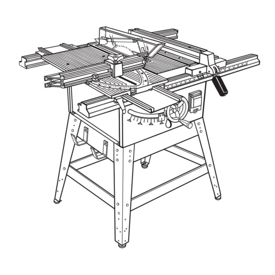
The rip fence is switch to operate the accessory. used to position work that will be cut lengthwise. A scale on the front rail shows the distance between the rip fence and the blade. ® TABLE SAW 315.228110... - Page 14 LOCKING HANDLE END CAP (4) SWITCH WITH LOCKABLE COVER MITER FENCE HOLDER BLADE ADJUSTING HANDLE STORAGE BRACKET(S) BEVEL LOCKING LEVER BEVEL SCALE BEVEL INDICATOR MITER LOCKING CLAMPS MITER TABLE BASE LEG STAND LEVELING FOOT Figure 5 ® TABLE SAW 315.228110...
-
Page 15: Features
BLADES See Figure 7. For maximum performance, it is recommended that you use the Craftsman 40 tooth, 10 inch carbide tipped combination blade provided with your saw. It is Figure 7 a high-quality carbide tipped combination blade suitable for ripping and crosscut operations. Other recommended blades are listed in the accessory section of this manual. -
Page 16: Assembly
Place an upper side brace inside two of the legs, UPPER BRACE BOLT HEX NUT WASHER UPPER WASHER CARRIAGE SIDE BRACE BOLT WASHER HEX NUT HEX NUT SCREW STORAGE LOWER BRACE BRACKET(S) WASHER HEX NUT LEVELING FOOT Figure 8 ® TABLE SAW 315.228110... -
Page 17: Assembling Storage Brackets
HEX NUT 4 hex bolts (1/4-20 x 3/4 in.) 4 hex nuts (1/4-20) 8 flat washers (1/4-20) Figure 10 Note: This hardware was in the bag with hardware for assembling the leg stand and leveling feet. ® TABLE SAW 315.228110... -
Page 18: Assembly Of Rails, Tables, And Fences
Note: Hole “A” should be used for short pieces of wood and hole “B” should be used for long pieces of wood. Adjust the miter indicator to the scale. MITER Retighten the adjusting clamp. TABLE BASE REAR RAIL Figure 13 ® TABLE SAW 315.228110... -
Page 19: To Install Accessory Table And Rip Fence
See To Set the Scale to the Blade in the SCREW LOCKING HANDLE Operation Section. In cutting operations, the scale SCALE INDICATOR FRONT LIP Figure 16 will be set to the side of the blade where the cut will be measured and made. ® TABLE SAW 315.228110... -
Page 20: To Install Blade Guard
Reinstall the throat plate into BLADE WASHER the opening, lower the blade and secure the three attachment screws. Tighten the screws securely. ARBOR NUT TIGHTEN Figure 18 RIVING KNIFE SHIMS HEX NUTS MOUNTING PLATE Figure 19 ® TABLE SAW 315.228110... -
Page 21: Operation
Miter cuts may tend to “creep” away from the miter fence during cutting. This can be controlled by holding the workpiece securely against the miter fence. The miter clamp kit has been de- Figure 23 signed and tested for this purpose. ® TABLE SAW 315.228110... -
Page 22: Cutting Tips
Knock out any loose knots with a hammer before making the cut. Always provide proper support for the wood as it comes out of the saw. See the Accessories Section in this manual for a list of recommended blades. ® TABLE SAW 315.228110... -
Page 23: Settings And Adjustments
Push bevel locking lever to the left to allow blade elevation and lowering. TO RAISE BLADE, PUSH BEVEL TO LOCK BLADE ANGLE, LOCKING LEVER LEFT AND PUSH BEVEL LOCKING ROTATE BLADE ADJUSTING LEVER LEFT HANDLE CLOCKWISE Figure 29 ® TABLE SAW 315.228110... -
Page 24: To Check Replace Or Adjust The Riving Knife And Blade Guard Assembly
Bring the blade back to the desired angle and GUARD ASSEMBLY height. Insert the throat plate, lower the blade, and secure the throat plate with the three throat plate screws. Tighten the screws firmly. TO CENTER RIVING KNIFE, REARRANGE SHIMS Figure 32 ® TABLE SAW 315.228110... -
Page 25: To Reduce The Risk Of Kickback
Use featherboards and push sticks to control non- through cuts on small workpieces. Figure 34 ® TABLE SAW 315.228110... -
Page 26: To Make A Push Stick
45°. See page 29 for information 3/8 INCH DIAMETER ° 3-5/8 in. 1/4 in. 1-13/16 in. ° 1/8 in. 6 in. 3/4 in. 8 in. 10 in. 12 in. 18 in. Figure 35 ® TABLE SAW 315.228110... -
Page 27: To Adjust Blade Depth
Adjust the front rail until the 2 in. mark is placed at the scale indicator. Align the rear rail to the front rail. SCALE Tighten the rails and check the dimension and the INDICATOR SCALE rip fence in both directions. 2 INCH MARK FRONT RAIL Figure 38 ® TABLE SAW 315.228110... -
Page 28: To Lock Miter Table
Table in Accessories on page 9. Make sure the wood is clear of the blade before turning on the saw. PADLOCK To turn saw On, lift switch cover and press switch (NOT PROVIDED) button. Then lower switch cover. Figure 41 ® TABLE SAW 315.228110... -
Page 29: To Make A Miter Cut
Remove the miter fence. Position accessory table and sliding miter table to provide the support necessary LOCKING HANDLE for the cut being performed. Securely lock the rip BASE FRONT RAIL Figure 43 fence with the locking handle. ® TABLE SAW 315.228110... -
Page 30: To Make A Bevel Cross Cut
5 in. and lock securely. wide. Attach the rip fence over the front and rear rails on the left side and lock securely. Reset the scale to the blade if needed. ® TABLE SAW 315.228110... -
Page 31: To Make A Compound Miter Cut
Let the blade build up to full speed before feeding the miter locking clamps to release the grippers. the workpiece into the blade. Remove the accessory table by swinging out the lever and lifting the table up and out. ® TABLE SAW 315.228110... -
Page 32: To Make Non-Through Cuts
Always use push blocks, push sticks, and featherboards when making non-through cuts to avoid the risk of serious injury. See Figure 47. ® TABLE SAW 315.228110... -
Page 33: To Make Dado Cuts
All blades must be rated for at least to get the correct width for the dado blade. 5,500 RPM to prevent possible injury or damage Mount the dado blade, using the instructions with to the tool. the dado set. ® TABLE SAW 315.228110... -
Page 34: Maintenance
If the blade is not an exact 45 degrees, loosen the lock nut on the 45 degree bolt inside the cabinet, position the blade, adjust the bolt, then retighten lock nut. See Figure 48, insert. Make a test cut. ® TABLE SAW 315.228110... -
Page 35: To Check The Alignment Of The Rip Fence To The Blade
Figure 50. Make sure the cam is HANDWHEEL Figure 50 ADAPTER seated in the lever. Reassemble the handle to the shaft and cam. Check whether the lever is now in the desired position. Tighten screw securely. ® TABLE SAW 315.228110... -
Page 36: To Align The Miter Locking Clamps
180° and reinstall on the handle shaft. Reassemble all parts and tighten hex nut securely. RETAINING Note: The spring plate offers two ends for use HANDLE RING before requiring replacement. SHAFT SPRING PLATE BACKUP PLATE HEX NUT Figure 53 ® TABLE SAW 315.228110... -
Page 37: Sliding Miter Table Assembly
0° scale settings when miter base adjustments are required. Note: These checks and adjustments are being explained in step by step procedures, however, you should be aware that they depend upon each other. ® TABLE SAW 315.228110... -
Page 38: Checking Sliding Miter Table Assembly
If not, this indicates the miter base needs aligning. Figure 55 Miter base must then be adjusted before checking miter fence alignment. See "To Adjust The Miter Base" section that follows. ® TABLE SAW 315.228110... -
Page 39: To Check Miter Fence Alignment
Following steps 2 thru 8 in "To Check Miter Base Parallelism", adjust the miter base so that it is parallel to the blade. Retighten the left front screw (N). Clamp the rear miter locking clamps (M). Figure 57 Retighten the two rear screws (L). ® TABLE SAW 315.228110... -
Page 40: To Adjust The Miter Fence
If sliding miter table assembly is still not square with the blade, repeat the above procedures as needed. Make sure that slides remain square to miter base edge to prevent “cocking” which will result in excessive play in miter table. ® TABLE SAW 315.228110... -
Page 41: To Adjust Quick Stop
Adjust eccentric screw until it holds quick-stop securely against miter fence. Retighten hex nut, securing eccentric screw and MITER quick-stop. FENCE Check your work. If the quick-stop is not at zero degrees, repeat steps 1-4. QUICK STOP AND ECCENTRIC SCREW Figure 60 ® TABLE SAW 315.228110... -
Page 42: Lubrication
Add dry lube on the inner surfaces of the bevel HANDWHEEL locking lever which contacts the cam. ADAPTER HANDLE SHAFT COMPRESSION SPRING BEVEL LOCKING LEVER BLADE ADJUSTING HANDLE Figure 62 ® TABLE SAW 315.228110... - Page 43 NOTES ® TABLE SAW 315.228110...
-
Page 44: Troubleshooting
Blade not properly sharpened or set. Re-sharpen or set blade. Sliding miter table assembly does Miter base or slides improperly See page 37 for Adjustments To not move smoothly. adjusted. Sliding Miter Table Assembly ® TABLE SAW 315.228110... -
Page 45: Troubleshooting
Locking lever is not at full left Move locking lever to left. position. Motor labors in rip cut. Blade not proper for rip cut. Change blade; rip blade typically has fewer teeth. ® TABLE SAW 315.228110... -
Page 46: Exploded View And Repair Parts List
CRAFTSMAN 10 in. TABLE SAW – MODEL NO. 315.228110 FIGURE A: 10 in. TABLE SAW FOR BLADE GUARD ASSEMBLY, FOR RIP FENCE ASSEMBLY, FOR LEG STAND ASSEMBLY, FOR MITER TABLE ASSEMBLY, REFER TO FIGURE D REFER TO FIGURE C REFER TO FIGURE F... - Page 47 CRAFTSMAN 10 in. TABLE SAW – MODEL NO. 315.228110 PARTS LIST – FIGURE A The model number will be found on a plate attached to the side panel of the cabinet. Always mention the model number in all correspondence regarding your TABLE SAW or when ordering repair parts.
- Page 48 CRAFTSMAN 10 in. TABLE SAW – MODEL NO. 315.228110 PARTS LIST – FIGURE A – Cont'd Part Part Number Description Quan. Number Description Quan. 662329-001 V Belt ........2 969173-007 Accessory Table ...... 1 662062-001 1/4 in. Spacer ......1 969174-004 Handle Shaft ......
- Page 49 CRAFTSMAN 10 in. TABLE SAW – MODEL NO. 315.228110 FIGURE B: SLIDING MITER TABLE ASSEMBLY Key Part Key Part No. Number Description Quan. No. Number Description Quan. 969177-004 Miter Table Top ....... 1 607617-003 *O-Ring ........4 969188-001 Miter Fence ......1 621721-010 Washer ........
- Page 50 CRAFTSMAN 10 in. TABLE SAW – MODEL NO. 315.228110 FIGURE C: RIP FENCE ASSEMBLY 14 15 Key Part Key Part No. Number Description Quan. No. Number Description Quan. 969144-001 Rip Fence ........ 1 14 ** STD541008 *Hex Nut (8-32) ......1...
- Page 51 CRAFTSMAN 10 in. TABLE SAW – MODEL NO. 315.228110 FIGURE D: BLADE GUARD ASSEMBLY Key Part No. Number Description Quan. 1 968700-004 *Screw (#6-19 x 5/16 in. Pan Hd.) ..2 2 969169-001 Anti-kickback Fingers ....2 3 662002-001 Spacer Cap ....... 2 4 969608-001 Torsion Spring ......
- Page 52 CRAFTSMAN 10 in. TABLE SAW – MODEL NO. 315.228110 The model number will be found on a plate attached to the side panel of the cabinet. Always mention the model number in all correspondence regarding your TABLE SAW or when ordering repair parts.
- Page 53 CRAFTSMAN 10 in. TABLE SAW – MODEL NO. 315.228110 The model number will be found on a plate attached to the side panel of the cabinet. Always mention the model number in all correspondence regarding your TABLE SAW or when ordering repair parts.
- Page 54 In U.S.A. or Canada for in-home major brand repair service: Call 24 hours a day, 7 days a week 1-800-4-MY-HOME (1-800-469-4663) Para pedir servicio de reparación a domicilio – 1-800-676-5811 Au Canada pour tout le service ou les pièces – 1-800-469 4663 For the repair or replacement parts you need: Call 6 a.m.