Table of Contents
Advertisement
Available languages
Available languages
Owner's Manual
"l
I CRFIFTSMRN°,,
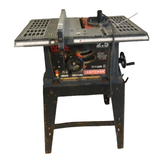
2.5 HP (Maximum Developed)
10" Inch Blade
5000 R.P.M.
TABLE SAW ,
Model No.
lO.in.
CAUTION:
Safety Instructions
Before using this Table Saw,
Installation
read this manual and follow
Operation
all its Safety Rules and
Maintenance
Operating Instructions.
Parts List
EspaSol
Iosomo.e .
1-800-843-1682
Sears, Roebuck and Co., Hoffman Estates, IL 60179 USA
Part No. 137221960001
Advertisement
Table of Contents

Related Manuals for Craftsman table saw


Summary of Contents for Craftsman table saw
- Page 1 Owner's Manual I CRFIFTSMRN°,, "l 2.5 HP (Maximum Developed) 10" Inch Blade 5000 R.P.M. TABLE SAW , lO.in. Model No. CAUTION: Safety Instructions Installation Before using this Table Saw, Operation read this manual and follow Maintenance all its Safety Rules and Parts List Operating Instructions.
-
Page 2: Specifications
SECTION PAGE Warranty ..............Product Specifications ............. Safety instructions ............Accessories and Attachments ..........Tools needed for assembly ..........Carton Contents ............Know Your Table Saw ............Assembly and Adjustments ..........Operation .............. Maintenance ............Troubleshooting guide ............ Parts ..............Making a push stick ............ - Page 3 GENERAL SAFETY INSTRUCTIONS WEAR YOUn ALWAYS WEAR EYE PROTECTION. Any table BEFORE USING THE TABLE SAW saw can throw foreign objects into the eyes which Safety is a combination of common sense, staying alert could cause permanent eye and knowing how to use your table saw damage ALWAYS wear Safety Goggles (not glasses) that comply with ANSI safety standard Z87 1...
- Page 4 PROVIDE ADEQUATE SUPPORT to the rear and 23. DIRECTION OF FEED, Feed work into a blade or cutter sides of the saw table for wide or long workpieces, against the direction of rotation of the blade or cutter only AVOID KICKBACKS (work thrown back towards you) by keeping the blade sharp, keeping the rip 24.
- Page 5 GROUNDING INSTRUCTIONS Fig. A IN THE EVENT OF A MALFUNCTION OR BREAKDOWN, 3-Prong Plug grounding provides a path of least resistance for electric current and reduces the risk of electric shock This tool is equipped with an electric cord that has an equipment grounding conductor and a grounding plug, The plug MUST be plugged into a matching receptacle that is Grounding Prong...
- Page 6 Also do not use molding head set with this saw Visit your Sears Hardware Department or see the If any parts are missing or damaged, do not attempt to Craftsman Power and Hand Tools Catalog to purchase assemble the table saw, plug in the power cord, or turn recommended accessories for this power tool.
-
Page 7: In The Box
UNPACKING YOUR TABLE SAW: • 7,r- -'5" -_ I° °1... -
Page 8: Product View
Blade g insert Miterg Ripfence Table lO.in. Blade bevel s cale TABLE SAW Blade bevel lock knob Overload reset Blade tilting switch handwheel ONtOFF switch withkey Blade elevation handwheel Toothan Tool hanger Mounting holes Leg stand Kickback pawls Splitter Blade Splitter bracket _nches Mounting hole... -
Page 9: Assembly
ASSEMBLY INSTRUCTIONS SAW TO LEG SET (FIG. B) Before mounting the rip fence and miter gauge to the saw top, invert the saw table so that it is facing the floor. For your own safety, never connect plug to power source Position the leg set upside down on the saw base outlet until all assembly steps are complete, and you have Match the holes of the stand to the holes on the... - Page 10 SAWMOUNTED T OOTHER SURFACES ( FIG.C) Fig. D 1 If thelegsetwill notbeused, t hesawmustbe properly secured to'asturdy workbench u singthefour mounting holesatthebaseofthesaw 2 Thesurface ofthetable where thesawis tobe mounted m usthavea holelarge enough tofacilitate sawdust fall-through a ndremoval. 3_ Square the sawonthemounting s urface andmark thelocation of thefour3/8"mounting holes(1) Dril!3/8"holesintothemounting s urface_ 5.
-
Page 11: Rip Fence
Raise the blade arbor (3) (FIG, I) to the maximum RIP FENCE (FIG. G) height by turning the blade raising handwheel Thread the fence handle (1) into the cam hole counterclockwise until tight Remove the arbor nut (4) and flange (5) Lift upward on the rip fence handle (1) so that the install the saw blade onto the arbor with the blade holding clamp (3) is fully extended... -
Page 12: Blade Guard Assembly
Fig. M BLADE GUARD ASSEMBLY (FIG, K, L, M, N) To avoid injury from an accidental start, make sure the switch is in the OFF position and the plug is not connected to the power source outlet. Set the blade to maximum height and the tilt to zero degrees on the bevel scale, Lock the blade lock knob, Place the external tooth tockwasher (2) followed by a... -
Page 13: Adjustment
Lock the fence handte..The fence should be parallel MITER GAUGE ADJUSTMENT (FIG_ O) Make sure that the miter gauge will slide freely through with the miter gauge groove. both table grooves If adjustment is needed to make the fence parallel to Loosen the lock knob (t) Set the pointer (2) to the 900 the groove, do the following: mark on the scale. - Page 14 Fig. R To avoid injury from an accidental start, make sure the switch is in the OFF position and the plug is not connected to the power source outlet. ADJUSTING THE 900 AND 45 ° POSITIVE STOPS (FIG. Q, R) Your saw has positive stops that will quickly position the saw blade at 90 o or 45 o to the table, These stops were set at the factory Make adjustments oniy if necessary...
- Page 15 BLADE PARALLEL TO THE MITER GAUGE GROOVE ADJUSTING THE BLADE TO BE PARALLEL TO (FIG. S) THE MITER GAUGE GROOVE (FIG.T) 1_ If the front and rear measurements are not the same, remove the combination square and loosen the four adjusting screws (1) on the top of the table To prevent personal injury, always disconnect plug from about a half turn, the power source when making any adjustments,...
-
Page 16: Basic Saw Operations
BASIC SAW OPERATIONS Fig. V RAISING THE BLADE (FIG, U) To raise or lower the blade, turn the blade elevation handwheel (1) to the desired blade height, and then tighten lock handle (2) to maintain the desired blade RESET angle,, OVERLOAD PROTECTION (FIG. - Page 17 RIPPING Never pull the workpiece back when the blade is (FIG. W, X) turning Turn the switch OFE When the blade completely stops raise the anti-kickback pawls on each side of the splitter and slide the workpiece out Do not allow familiarity gained from the frequent use of your table saw to cause careless mistakes.
- Page 18 Fig. Z CROSSCUTTING (FIG. Y) Do not allow familiarity gained from the frequent use of your table saw to cause careless mistakes, Remember that even a careless fraction of a second is enough to cause a severe injury Remove the rip fence and place the miter gauge in the left side groove, Adjust the blade height so it is 1/8"...
- Page 19 MITERING (FIG. BB) It is not necessary to install the outside flange (2) This sawing operation is the same as crosscutting except before screwing on the arbor nut (3) Make sure that the miter gauge is locked at an angle other than 90 ° the arbor nut (3) is tight, and that at least one thread Hold the workpiece (2) firmly against the miter of the arbor sticks out past the nut...
-
Page 20: Maintaining Table Saw
MAINTAINING YOUR TABLE SAW Fig. EE GENERAL MAINTENANCE For your own safety, turn the switch OFF and remove the switch key. Remove the plug from the power source outlet before maintaining or' lubricating your saw.. Clean out all sawdust that has accumulated inside the saw cabinet and the motor Polish the saw table with an automotive wax to keep it clean and to make it easier to slide the workpiece... - Page 21 TROUBLESHOOTING GUIDE To avoid injury from an accidental start, turn the switch OFF and always remove the plug from the power source before making any adjustments. • Consult your local Sears Service Center if for any reason the motor will not run SYMPTOM POSSIBLE CAUSES CORRECTIVE ACTION...
-
Page 22: Parts List
10" TABLE SAW PARTS LIST MODEL NO. 137.221960 When servicing use only CRAFTSMAN replacement parts. Use of any other parts may create a HAZARD or cause product damage Any attempt to repair or replace electrical parts on this Table Saw may create a HAZARD unless... - Page 23 10" TABLE SAW PARTS LIST MODEL NO. t37.221960...
- Page 24 CRAFTSMAN TABLE SAW LEG STAND 137.221960 When servicing use only CRAFTSMAN replacement parts, Use of any other parts may create a HAZARD or cause product damage, Any attempt to repair or replace electrical parts on this table saw may create a HAZARD unless repair is done by a qualified service technician Repair service is available at your nearest Sears Service Center.
- Page 25 CRAFTSMAN TABLE SAW LEG STAND 137.221960...
- Page 26 .£2...
- Page 29 iVlanual d e Operaci6n CRFIFTSM 2.5 HP (Potencia M_xima) Hoja Circular de 25.4cm (10") 5000 R.P.M. tO.in. TABLE Modelo No. 137.221960 CUIDADO: • Instrucciones de Seguridad • Instalaci6n Antes de usar esta sierra de mesa, leer este manual y seguir todas sus •...
- Page 30 SECCION P,_,GINA Garantia ..............Especificaciones de la Herramienta .......... lnstrucciones de Seguridad ..........Accesorios y Aditamentos ..........Herramientas necesarias para el ensamblaje ........Contenido de la Caja ............Familiarizarse con la Sierra de Mesa .......... Ensamblaje y Regulaci6n ..........Operaci6n ............... Mantenimiento ............
- Page 31 INSTRUCClONES GENERALESDE USAR StEMPREUSAR PROTECClON PARA LOS OJOS. Cualquier SEGURIDAD sierrade mesa puede arrojar obietosextraSosa tos ojos ANTES DE USARLA SIERRADE MESA causandodaSosserios permanentes SIEMPRE La seguridad es una combinaciSnde sentido comun, mantenerse usar Galasde Seguridad (no alerta y conocercomo funciona la sierra de mesa anteojos) que cumptancon la normaZ87 1 de ANSI Los anteojos de uso diario s61o tienen lentes resistentesa los impactos,estos NO SONgafas de seguridad.Las Galas...
- Page 32 PROVEERSOPORTE ADECUADO en las partes posterior 23. AVANZAR la pieza de trabajo s61oen direcci6n contrafia y tateralesde ia hoja cuando se corten piezas anchas a la rotaci6n de la hoja o largas. 24. ADVERTENCIA: El polvo generado pot ciertos matefiales EVITARGOLPES DE RETROCESO(pieza de trabajo puede set nocivo para ta salud.
- Page 33 INSTRUCCiONES PARA LA CONEXlON ATtERRA Fig. Enchub de 3 espigas EN EL EVENTO DE UNA FALLA O MAL FUNCIONAMIENTO, la conexi6n a tierra provee una via de menor resistenciapara la corriente electrica, reduciendoasi el riesgo de choque electrico Esta herramientaest_ equipada con un cord6n el_ctricoque tiene un conductor para conexbn a tierra y tambien con un Espigaparaconexi6n a tierra...
- Page 34 ACCESORIOS RECOMENDADOS DESEMBALAJE Y VERIFICACIONDEL CONTENIDO Separar todas las piezas de sus envolturas. Antes de descartar En esta sierra no se debe usar hojas ranuradorasde tipo cualquier materiatde embalaje,verificar tas piezas contra la regulable ni hojas con dientes de carburo. El ancho m_ximo para ilustraci6n en la siguiente pagina y la lista a continuaci6n para vet ranurar es 12 7ram (1/2").No usar hojas ranuradorasde m_.sde que esten completas...
- Page 35 DESEMBALAJE DE LA SIERRA DE MESA: iO-in. 2.5/tl tl ©...
- Page 36 Insertode Ia mesa Cubierta protectora de la hoja Medidor de anguto Barrera de corte en inglete Mesa lO.in. Escata para TABLE SAW angulo de corte en bisel Manija de fijacion del anguto de corte en bisel Bot6n reposicionador Maniveta de inelinaci6n del interruptor de sobrecarga de la hoja...
- Page 37 INSTRUCCIONES PARAEL ENSAMBLAJE MONTAJE DE LA SIERRA AL JUEGO DE PATAS(FIG. B) Antes de instalarla barrera guia y el medidor de ingtete sobre el tablerode la sierra, colocar la sierra invertida con el tablero sobre el piso For su propia seguridad,nunca enchufar at tomacorriente hasta Invertirel juego de patas y co]ocarlosobre la base de la haber completado todos los pasos del ensambiaje y hasta haber sierra°...
- Page 38 MONTAJE DE LA SIERRA EN OTRAS SUPERFICIES (FIG. C) Fig. D Si no se va a usar el juego de patas,la sierra debe montarse y sujetar adecuadamentea un banco de trabajo robusto usando los cuatro orificios para pernos de montaje que est_n en la base de la sierra..
- Page 39 BARRERA (FIG, G) Subir el eje portasierra (3) (Fig. t) al m__ximo girando la Enroscar el mango (1) de la barreraen orificio (2) de la leva manivela elevadoracontra el sentido del reloj hasta que ajuste Sacar ia tuerca del eje portahoja (4) y la brida (5). Levantar la barrera pot el mango (I) de modo que el lnstalar la hoja de la sierra en el eje portahoja con los sujetador (3) quede completamenteextendido.
- Page 40 ENSAMBLAJE DEL PROTECTOR DE LA HOJA (FIGS.K, L, M, N) Fig. M Para evitar tesiones debidas a un ar_anqueaccidenta! de la sierra, cerciorarseque el interruptor est_ en "OFF" (Apagado) y que el enchufe est6 desconectado del tomacorriente. CoIocar la hoja en su posici6n mas alta y perpendicuiar,a 0° en la escala de _ngulos para cortes en biseLAjustar {a perilla de fijaciSn de la hoja.
- Page 41 REGULACION DEL MEDIDORDE ANGULOS DE CORTE EN Ajustar ta manija (2) de la barrera La barrera debe estar parateta a la ranurapara el medidor del angulo de corte en INGLETE (FIG, O) ingtete. Cerciorarse que el medidor del angulo de corte en inglete se Si se necesita hacerajustes para poner ta barrera paralela a destice librementepor ambas ranuras de la mesa Ia ranura, hacer Io siguiente:...
- Page 42 Fig. R Para evitar lesiones debidas a un arranque accidental de la sierra, cerciorarse que el interruptorest_ en "OFF" (Apagado) y que el enchufe este desconectadodel tomacorriente.. REGULAClON DE LOSTOPES DE FABRICA A 900Y 450 (FIG. Q, R) La sierra viene de f_brica con topes que permiten colocar la mesa rapidarnenteen las posiciones de 90o y 450 Hacer ajustes unicamente si es necesario Tope a 900...
- Page 43 PARALELISMODE LA HOJA CON LA RANURA PARA EL REGULAClON DELPARALEL1SMO DE LA HOJACON LA MEDIDOR DE CORTE EN INGLETE (FIGoS) RANURAPARAEL MEDIDORDE CORTESEN INGLETE(FIG,T) Si fa medida de la distancia en el frente y atr_s no es igual, retirarla escuadracombinada y aftojar los cuatro pernos de fijaci6n (1) que estan sobre ta mesa aproximadamente Para evitar Iesiones personales siempre desenchufarel cord6n mediavuelta...
- Page 44 Fig. V O;;£;, ,j OiOlqES BASICAS DE CORTE ELEVACIONDE LA HOJA (FIG, U) Para elevaro bajar la l';oia:4,= la sierra, girar fa maniveta(1) hasta lograr Ia altum :'.:_-;;_,ua y votver a ajustar fa manija de fijaci6n (2) para manterier la aitura deseada RESET PROTECCtON DE SOBRECARGA (FIG.
- Page 45 Nunca halar la pieza de trabajode retrocesocuando la hoja CORTE A LO LARGO DE LA HEBRA (FIG. W, X) este girando Apagar la sierra Cuando fa hoja se detenga completamente subir los trinquetes a cada lado del soporte separador y deslizar la pieza de trabajo fuera de la mesa No permitir que et exceso de familiaridad basada en et uso frecuente de la sierrahaga cometer descuidos Recordar que una Fig.
- Page 46 Fig. Z CORTE CRUZADO (FIG. Y) No permitir que el exceso de familiaridad basada en el uso frecuente de ta sierra se convieda en descuido. Recordar que una fracci6n de segundo de descuido es suficiente para causar una lesi6n severa. Sacar la barrera de la mesa y colocar el medidor para corte en inglete en la ranura izquierdade la mesa, Subir la hoja hasta que quede a 3ram (t/8") sobre la pieza...
- Page 47 No es necesario instalar ta brida exterior (2) antes de CORTE EN INGLETE (FIGoBB) enroscar fatuerca (3) del eje porta hoja. Cerciorarseque e! Este corte es igua! al corte cruzado, exceptoque el medidor para eje portahoja(3) quede ajustado y que pot Io menos una corte en inglete est_ fijado en un _ngulo diferentea 900 vuelta de rosca del eje sobresalga de Ia tuerca.
- Page 48 MANTENIMIENTO DE LA SIERRA DE MESA Fig. EE MANTENIMIENTOGENERAL Para evitar tesionescausadas pot arranques inesperados de la sierra y quitar la Ilavedel interruptor Desconectar e! enchufe del tomacorriente antes de hacerie mantenimiento o lubricar la sierra EliminareI aserrin que se acumula dentro dei gabinete de ta sierra yen el motor.
- Page 49 GUJAPARAEL DIAGNOSTtCO DE PROBLEMAS Para evitar tesiones por arranquesaccidentales de la sierra, siempre colocar et interruptor en ta posici6n de "OFF" y desenchuiar el cord6n det tornacorrienteantes de iubricar o hacerle cuaiquier regulaci6na la sierra o Si el motor no funcionasepot cualquier rnotivo,consultar con el Centro de Servicio de Sears mas cercano SOLUCl()N PROBLEMA CA!!SA PROBABLE ......
- Page 50 MODEL NO. 137.221960 At darle sewicio a la m_quina, s61ousar de repuestos CRAFTSMAN.El use de cuatquierotto repuesto puede crear RIESGOS o daRar la herramientaCualquier intento de reparar o reemptazar las piezas el6ctricasde esta siena de mesa puede crear RIESGOS a manes que ia reparaci6n la haga un tecnico calificado de servicio.
- Page 51 LISTA DE PARTES DE LA SIERRA DE MESA DE 10" MODELO NO. 137.221960 _50 149t-1...
- Page 52 BANCOPARASIERRA DE MESA CRAFTSMAN 137.221960 N dar serviciosSlo usar repuestos CRAFTSMAN El uso de otros repuestos podria generar RIESGOSo daSar la unidad Cualquier intento de reparar este motor podria generar RtESGOS a menos que 1ohaga un etectricistacatificado, El Centro de...
- Page 53 BANCO PARA SIERRA DE MESA CRAFTSMAN 137.221960...
- Page 54 /,.._ .O_o Q.,.-- ...._c_E ..i .._E k "O / JYI:: _/.///...
- Page 56 iiill For in-home major brand repair service: Call 24 hours a day, 7 days a week 1-800-4=MY-HOME°_(_-800-469-4663) Para pedir servicio de reparaci6n a domicilio- 1-800-676-5811 In Canada for all your service and parts needs call - 1-800-665-4455 Au Canada pour tout ie service ou les pibces For the repair or replacement parts you need: Call 7 am - 7 pro, 7 days a week 1-800-366-PART (t-800-366-7278)