
Related Manuals for Gigabyte G593-ZD2-AAX1


Summary of Contents for Gigabyte G593-ZD2-AAX1
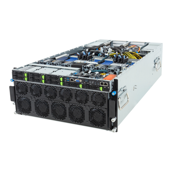
- Page 1 G593-ZD2-AAX1 HPC Server - 5U DP SXM5 H100 8-GPU Server System User Manual Rev. 1.0...
- Page 2 For GIGABYTE distributors and resellers, additional sales & marketing materials are available from our reseller portal: http://reseller.b2b.gigabyte.com For further technical assistance, please contact your GIGABYTE representative or visit https://esupport.gigabyte.com/ to create a new support ticket For any general sales or marketing enquiries, you may also message GIGABYTE server directly by email: server.grp@gigabyte.com...
- Page 3 Conventions The following conventions are used in this user's guide: NOTE! Gives bits and pieces of additional information related to the current topic. CAUTION! Gives precautionary measures to avoid possible hardware or software problems. WARNING! Alerts you to any damage that might result from doing or not doing specific actions.
- Page 4 Server Warnings and Cautions Before installing a server, be sure that you understand the following warnings and cautions. WARNING! To reduce the risk of electric shock or damage to the equipment: • Do not disable the power cord grounding plug. The grounding plug is an important safety feature.
- Page 5 Electrostatic Discharge (ESD) CAUTION! ESD CAN DAMAGE DRIVES, BOARDS, AND OTHER PARTS. WE RECOMMEND THAT YOU PERFORM ALL PROCEDURES AT AN ESD WORKSTATION. IF ONE IS NOT AVAILABLE, PROVIDE SOME ESD PROTECTION BY WEARING AN ANTI-STATIC WRIST STRAP AT- TACHED TO CHASSIS GROUND -- ANY UNPAINTED METAL SURFACE -- ON YOUR SERVER WHEN HANDLING PARTS.
- Page 6 CAUTION! Risk of explosion if battery is replaced incorrectly or with an incorrect type. Replace the battery only with the same or equivalent type recommended by the manufacturer. Dispose of used bat- teries according to the manufacturer’s instructions.
-
Page 7: Table Of Contents
Table of Contents Chapter 1 Hardware Installation ...................10 Installation Precautions .................. 10 Product Specifications ..................11 System Block Diagram ................... 15 PCIe Block Diagram ..................16 Chapter 2 System Appearance ..................17 Front View ...................... 17 Rear View ....................... 18 Front Panel LED and Buttons ................ 19 2-3-1 RoT LEDs .......................20 Front Panel System LAN LEDs .............. - Page 8 3-13-3 Motherboard to PCIe Board and HDD Backplane Board ........46 Chapter 4 Motherboard Components ................48 Motherboard Components ................48 Jumper Setting ....................50 Backplane Board Storage Connector ............51 4-3-1 CBPG680 .......................51 Chapter 2 BIOS Setup ....................52 The Main Menu ....................54 Advanced Menu .....................
- Page 9 AMD PBS Menu ................... 145 5-4-1 RAS ........................146 Chipset Setup Menu ..................148 5-5-1 North Bridge ......................149 5-5-2 Fabric Resource ....................150 Server Management Menu ................152 5-6-1 System Event Log ....................154 5-6-2 View FRU Information ..................155 5-6-3 BMC Network Configuration .................156 5-6-4 IPv6 BMC Network Configuration .................157 Security Menu ....................
-
Page 10: Chapter 1 Hardware Installation
Chapter 1 Hardware Installation Installation Precautions The motherboard/system contain numerous delicate electronic circuits and components which can become damaged as a result of electrostatic discharge (ESD). Prior to installation, carefully read the user manual and follow these procedures: • Prior to installation, do not remove or break motherboard S/N (Serial Number) sticker or warranty sticker provided by your dealer. -
Page 11: Product Specifications
Product Specifications NOTE: We reserve the right to make any changes to the product specifications and product-related information without prior notice. System Š 447 x 222.25 x 945 (W x H x D, mm) Dimension Š Socket Security Server Operating Properties AMD EPYC™... - Page 12 Expansion Slot Supports NVIDIA HGX™ H100 with 8 x SXM5 GPUs Š 8 x PCIe x16 (Gen5 x16) low-profile slots, from PEX89104 Š 2 x PCIe x16 (Gen5 x16) FHHL slots, from CPU_0 Š Security Server Socket Operating Properties 2 x PCIe x16 (Gen5 x16) FHHL slots, from CPU_1 Š...
- Page 13 Different SKUs have different PSU specs, so please see the system rating label on the server for the accurate PSU specification. System Aspeed® AST2600 management controller Management GIGABYTE Management Console (AMI MegaRAC SP-X) web interface Dashboard Š cket Security...
- Page 14 Security Server Socket Operating Properties System fan System fan System fan Power Supply System Fans Front: 5 x 80x80x80mm (17,200rpm), 6 x 60x60x76mm (21,700rpm) Š Rear: 6 x 80x80x80mm (17,000rpm), 4 x 40x40x56mm (29,700rpm) Š Internal: 4 x 40x40x28mm (25,000rpm), 4 x 60x60x56mm (24,000rpm) Š...
-
Page 15: System Block Diagram
System Block Diagram Hardware Installation - 15 -... -
Page 16: Pcie Block Diagram
PCIe Block Diagram CPU0 Domain CPU1 Domain Front Side HDD0 HDD2 HDD4 HDD1 HDD3 HDD5 HDD6 HDD7 SLOT12 SLOT11 SLOT10 SLOT9 Rear Side Gen5 x16 Gen5 x16 CPU1 CPU0 SLOT11 SLOT12 Gen5 x16 Gen5 x16 SLOT10 SLOT9 Gen5 x16 Gen5 x16 PCIe G5 Switch PCIe G5 Switch PCIe G5 Switch... -
Page 17: Chapter 2 System Appearance
Chapter 2 System Appearance Front View HDD0 HDD2 HDD4 HDD1 HDD3 HDD5 HDD6 HDD7 F_60 F_60 F_60 F_60 F_60 F_60 11/12 9/10 F_80 F_80 F_80 F_80 F_80 9/10 Description USB 3.2 Gen1 Port x 2 10/100/1000 Server Management LAN Port VGA Port Front Panel LEDs and Buttons 10GbE LAN Port x 2... -
Page 18: Rear View
Rear View SLOT11 SLOT12 PSU6 PSU3 SLOT10 SLOT9 PSU5 PSU2 R_80 R_80 R_80 PSU4 PSU1 R_80 R_80 R_80 11/12 9/10 Description PCIe Card Cage x 2 PCIe Slot x 4 10/100/1000 Server Management LAN Port System Appearance - 18 -... -
Page 19: Front Panel Led And Buttons
Front Panel LED and Buttons Name Color Status Description Reset Button Press the button to reset the system. Press the button server generates a NMI to the processor NMI button if the multiple-bit ECC errors occur, which effectively halt the server. HDD locate Green Blink... -
Page 20: Rot Leds
2-3-1 RoT LEDs Status LED ID LED LED on Front panel (Note5) ID LED Status LED EC Firmware (FW) Authentication fail or not exit EC FW is broken or not exit (Note1) Authenticating/Recovering BMC/BIOS Images Authenticating Images Blinks Blue Blinks Green Recovering BMC Active Flash 4 times per 4 times per... - Page 21 Blinks Blue Blinks Green 2 times per 2 times per BMC : AUTH fail after doing recovery (Note3) second second [ON OFF OFF] [ON OFF OFF] Blinks Blue Blinks Amber 2 times per 2 times per BIOS : AUTH fail after doing recovery (Note3) second second...
-
Page 22: Front Panel System Lan Leds
Front Panel System LAN LEDs Name Color Status Description Green 10 Gbps data rate 10GbE Yellow 5Gbps, 2.5Gbps, 1Gbps data rate Speed LED 100 Mbps data rate Link between system and network or no access Green 10GbE Link / Blink Data transmission or reception is occurring. -
Page 23: Power Supply Unit (Psu) Led
Power Supply Unit (PSU) LED PSU LED State Description No AC power to all power supplies 1Hz Green Blinking AC present / only standby on / Cold redundant mode 2Hz Green Blinking Power supply firmware updating mode AC cord unplugged or AC power lost; with a second power supply in parallel still with AC input power Amber Power supply critical event causing shut down:... -
Page 24: Hard Disk Drive Leds
Hard Disk Drive LEDs HDD Present RAID SKU Rebuilding LED1 Locate HDD Fault Access (No Access) Disk LED Green ON(*1) BLINK (*2) (LED on Back Panel) Amber No RAID configuration Green ON(*1) (via HBA) Removed HDD Slot (LED on Back Panel) Amber Green BLINK (*2) -
Page 25: Chapter 3 System Hardware Installation
Chapter 3 System Hardware Installation Pre-installation Instructions Computer components and electronic circuit boards can be damaged by electrostatic discharge. Working on computers that are still connected to a power supply can be extremely dangerous. Follow the simple guidelines below to avoid damage to your computer or injury to yourself. -
Page 26: Removing And Installing The Chassis Top Cover
Removing and Installing the Chassis Top Cover Before you remove or install the chassis top cover • Make sure the system is not turned on or connected to AC power. Follow these instructions to remove/install the chassis top cover: Front Cover Push button to unlock the handle. -
Page 27: Removing And Installing The Gpu Tray
Removing and Installing the GPU Tray Before you remove or install the GPU tray: • Make sure the system is not turned on or connected to AC power. Follow these instructions to remove/install the GPU tray: Loosen the top thumbnail screw securing the handles on both sides of the system. Pull the grip handles on both sides of the system slide the tray to the front of the system at the same time to pull out the tray. -
Page 28: Removing The Heat Sink
Removing the Heat Sink Read the following guidelines before you begin to remove/install the heat sink: • Always turn off the computer and unplug the power cord from the power outlet before installing the heat sink to prevent hardware damage. •... -
Page 29: Installing The Cpu
Installing the CPU Read the following guidelines before you begin to install the CPU: • Make sure that the motherboard supports the CPU. • Always turn off the computer and unplug the power cord from the power outlet before installing the CPU to prevent hardware damage. -
Page 30: Installing The Memory
Installing the Memory Read the following guidelines before you begin to install the memory: • Make sure that the motherboard supports the memory. It is recommended that memory of the same capacity, brand, speed, and chips be used. • Always turn off the computer and unplug the power cord from the power outlet before installing the memory to prevent hardware damage. -
Page 31: Installing The Memory
3-5-2 Installing the Memory Before installing a memory module, make sure to turn off the computer and unplug the power cord from the power outlet to prevent damage to the memory module. Be sure to install DDR5 DIMMs on this motherboard. Follow these instructions to install the Memory: Insert the DIMM memory module vertically into the DIMM slot, and push it down. -
Page 32: Dimm Population Table
3-5-4 DIMM Population Table EPYC Memory Speed based on DIMM Population (One DIMM per Channel) DIMM Population DIMM Max EPYC 9004 Type DDR5 Frequency (MT/s) DIMM 0 1R (1 Rank) 4800 RDIMM 2R (2 Ranks) 4800 2S2R (4 Ranks) 4800 3DS RDIMM 2S4R (8 Ranks) 4800... -
Page 33: Installing The M.2 Device And Heat Sink
Installing the M.2 Device and Heat Sink CAUTION The position of the stand-off screw will depend on the size of the M.2 device. The stand-off screw is pre-installed for 22110 cards as standard. Refer to the size of the M.2 device and change the position of the stand-off screw accordingly. -
Page 34: Installing The Pci Expansion Card
Installing the PCI Expansion Card • Voltages can be present within the server whenever an AC power source is connected. This voltage is present even when the main power switch is in the off position. Ensure that the system is powered-down and all power sources have been disconnected from the server prior to installing a PCIe card. - Page 35 Rear System PCIe Card Loosen the screw securing the riser bracket. Gently lift the riser bracket. Then, move it backward and lift it upward. Remove the screw securing the slot cover from the riser bracket. Remove the slot cover from the riser bracket. Orient the PCIe card with the riser guide slot and push in the direction of the arrow until the PCIe card sits in the PCIe card connector.
-
Page 36: Installing The Hard Disk Drive
Installing the Hard Disk Drive Read the following guidelines before you begin to install the hard disk drive: • Take note of the drive tray orientation before sliding it out. • The tray will not fit back into the bay if inserted incorrectly. •... -
Page 37: Replacing The System Fan Module
Replacing the System Fan Module CAUTION! Before you remove or install the system fans follow these steps: • Disconnect all necessary cable connections. Failure to observe these warnings could result in personal injury or damage to the equipment Follow these instructions to replace the fan assembly: Flip and then grasp the handle and simultaneously press the retaining clip on the bottom side of the fan module in the direction indicated. -
Page 38: Removing And Installing The Power Supply
3-10 Removing and Installing the Power Supply CAUTION! Please see Section 2-2 "Rear View" for installation sequence. Follow these instructions to replace the power supply: Flip and then grasp the power supply handle. Press the retaining clip on the right side of the power supply in the direction indicated. Pull out the power supply using the handle. -
Page 39: Installing The System Into The Cabinet
3-11 Installing the System into the Cabinet Read the following guidelines before you begin to install the system into the cabinet: • Make sure the system is not turned on or connected to AC power. • A Lift Table is required. Place the system unit on Lift Table. •... -
Page 40: Removing The System From The Cabinet
3-12 Removing the System from the Cabinet Read the following guidelines before you begin to remove the system from the cabinet: • Always turn off the computer and unplug the power cord from the power outlet before removing the system from the cabinet. •... - Page 41 NOTE! • Before lifting the system, installing the four chassis handles on the system is required. Follow these instructions to install the chassis handles on the system: Attach the four chassis handles to the system. Push and lock the thumbnail screw to secure the chassis handle in place. System Hardware Installation - 41 -...
-
Page 42: Cable Connection
3-13 Cable Connection 3-13-1 Motherboard to PCIe Board PEX1 PEX3 PEX0 PEX2 CPU0 CPU1 System Hardware Installation - 42 -... - Page 43 Motherboard: U2_P0_P1 PCIe Slot Signal Cable PCIe Board: U2_PEX0A Motherboard: U2_P0_P3 PCIe Slot Signal Cable PCIe Board: U2_PEX1A Motherboard: U2_P1_P1 PCIe Slot Signal Cable PCIe Board: U2_PEX2A Motherboard: U2_P1_P3 PCIe Slot Signal Cable PCIe Board: U2_PEX3A Motherboard: U2_P0_G3A1 XGMI Cable Motherboard: U2_P1_G1A1 Motherboard: U2_P0_G3B1 XGMI Cable...
-
Page 44: Motherboard/Front Io Board To Rear Side Fhhl Card Cable
3-13-2 Motherboard/Front IO Board to Rear Side FHHL Card Cable CPU0 CPU1 System Hardware Installation - 44 -... - Page 45 Motherboard: U2_P0_P0 PCIe Slot Signal Cable SLOT9 Motherboard: U2_P0_P2 PCIe Slot Signal Cable SLOT11 Motherboard: U2_P1_P0 PCIe Slot Signal Cable SLOT10 Motherboard: U2_P1_P2 PCIe Slot Signal Cable SLOT12 Front IO Board: REAR_LAN Rear Side MLAN Cable MLAN Card: CN_LAN1 Motherboard: F_USB1 USB Cable Front IO Board: F_USB3_CON Motherboard: U2_11...
-
Page 46: Motherboard To Pcie Board And Hdd Backplane Board
3-13-3 Motherboard to PCIe Board and HDD Backplane Board PEX1 PEX3 PEX0 PEX2 CPU0 CPU1 System Hardware Installation - 46 -... - Page 47 PCIe Board: P0_NV NVMe Cable Backplane Board: U_2_0/ U_2_1 PCIe Board: P1_NV NVMe Cable Backplane Board: U_2_2/ U_2_3 PCIe Board: P2_NV NVMe Cable Backplane Board: U_2_4/ U_2_5 PCIe Board: P3_NV NVMe Cable Backplane Board: U_2_6/ U_2_7 Motherboard: BP_1 Backplane Board Sideband Signal Cable PCIe Board: BP_1 PCIe Board: BP_SERIES...
-
Page 48: Chapter 4 Motherboard Components
Chapter 4 Motherboard Components Motherboard Components BIOS1 BIOS2 BMC1 BMC2 7 8 9 10 14 15 16 17 CPU0 CPU1 Motherboard Components - 48 -... - Page 49 Item Description Battery Cable Connector VGA Connector Serial Port Header BMC Firmware Readiness LED TPM Module Connector SlimLine Connector (for Delta Module Link) MCIO Connector (U2_P0_P0/PCIe Gen5) MCIO Connector (U2_P0_P1/PCIe Gen5) MCIO Connector (U2_P0_P2/PCIe Gen5) MCIO Connector (U2_P0_P3/PCIe Gen5) MCIO Connector (for System I/O) SlimLine Connector (for MLAN) SlimLine Connector (for Power Board Side Band Signal) MCIO Connector (U2_P1_P0/PCIe Gen5)
-
Page 50: Jumper Setting
Jumper Setting Clear CMOS Default CLR_CMOS Enable SMB_SEL BIOS Defined BIOS_PWD Clear supervisor password Normal [Default] Normal [Default] BIOS_RCVR BIOS recovery mode Motherboard Components - 50 -... -
Page 51: Backplane Board Storage Connector
Backplane Board Storage Connector 4-3-1 CBPG680 Item Description MCIO 4i (SFF-TA-1016 / U_2_0) MCIO 4i (SFF-TA-1016 / U_2_1) MCIO 4i (SFF-TA-1016 / U_2_2) MCIO 4i (SFF-TA-1016 / U_2_3) MCIO 4i (SFF-TA-1016 / U_2_4) MCIO 4i (SFF-TA-1016 / U_2_5) MCIO 4i (SFF-TA-1016 / U_2_6) MCIO 4i (SFF-TA-1016 / U_2_7) MCIO 4i (SFF-TA-1016 / SL_SAS0) MCIO 4i (SFF-TA-1016 / SL_SAS1) -
Page 52: Chapter 2 Bios Setup
Chapter 2 BIOS Setup BIOS (Basic Input and Output System) records hardware parameters of the system in the EFI on the motherboard. Its major functions include conducting the Power-On Self-Test (POST) during system startup, saving system parameters, loading the operating system etc. The BIOS includes a BIOS Setup program that allows the user to modify basic system configuration settings or to activate certain system features. - Page 53 Main This setup page includes all the items of the standard compatible BIOS. Advanced This setup page includes all the items of AMI BIOS special enhanced features. (ex: Auto detect fan and temperature status, automatically configure hard disk parameters.) ...
-
Page 54: The Main Menu
The Main Menu Once you enter the BIOS Setup program, the Main Menu (as shown below) appears on the screen. Use arrow keys to move among the items and press <Enter> to accept or enter other sub-menu. Main Menu Help The on-screen description of a highlighted setup option is displayed on the bottom line of the Main Menu. - Page 55 Parameter Description BIOS Information Project Name Displays the project name information. Project Version Displays version number of the BIOS setup utility. Build Date and Time Displays the date and time when the BIOS setup utility was created. BMC Information (Note1) BMC Firmware Version (Note1) Displays BMC firmware version information.
- Page 56 Parameter Description Onboard LAN Information LAN1/LAN2 MAC Address (Note) Displays LAN MAC address information. System Date Sets the date following the weekday-month-day-year format. System Time Sets the system time following the hour-minute-second format. (Note) The number of LAN ports listed will depend on the motherboard / system model. BIOS Setup - 56 -...
-
Page 57: Advanced Menu
Advanced Menu The Advanced Menu displays submenu options for configuring the function of various hardware components. Select a submenu item, then press <Enter> to access the related submenu screen. When Boot Mode Select is set to UEFI (Default) When "Boot Mode Select" is set to Legacy in the Boot > Boot Mode Select section BIOS Setup - 57 -... -
Page 58: Trusted Computing
5-2-1 Trusted Computing Parameter Description Configuration Enable/Disable BIOS support for security device. OS will not show security device. TCG EFI protocol and INT1A interface will not be Security Device Support available. Options available: Disable, Enable. Default setting is Enable. Select Enable to activate TPM support feature. SPI TPM Support Options available: Disabled, Enabled. -
Page 59: Psp Firmware Versions
5-2-2 PSP Firmware Versions The PSP Firmware Versions page displays the basic PSP firmware version information. Items on this window are non-configurable. BIOS Setup - 59 -... -
Page 60: Legacy Video Select
5-2-3 Legacy Video Select Description Parameter Selects between onboard or external VGA support. OnBrd/Ext VGA Select Options available: Auto, Onboard, External. Default setting is Auto. This configurable option will be displayed when "Boot Mode Select" is set to Legacy in the Boot > (Note) Boot Mode Select section. -
Page 61: Ast2600 Super Io Configuration
5-2-4 AST2600 Super IO Configuration Description Parameter AST2600 Super IO Configuration Super IO Chip Displays the super IO chip information Serial Port 1 Press [Enter] for configuration of advanced items. Configuration BIOS Setup - 61 -... - Page 62 5-2-4-1 Serial Port 1 Configuration Description Parameter Serial Port 1 Configuration Enable/Disable the Serial Port (COM). When set to Enabled allows you to configure the Serial port 1 settings. When set to Disabled, displays no Serial Port (Note) configuration for the serial port. Options available: Disabled, Enabled.
-
Page 63: S5 Rtc Wake Settings
5-2-5 S5 RTC Wake Settings Parameter Description Enable/Disable system wake on alarm event. Options available: Disabled, Fixed Time, Dynamic Time. When Fixed Time Wake System from S5 is selected, system will wake on the hr::min::sec specified. Default setting is Disabled. BIOS Setup - 63 -... -
Page 64: Serial Port Console Redirection
5-2-6 Serial Port Console Redirection Parameter Description Select whether to enable console redirection for specified device. Console COM1/Serial Over LAN redirection enables the users to manage the system from a remote Console Redirection (Note) location. Options available: Enabled, Disabled. Default setting is Disabled. Press [Enter] to configure advanced items. - Page 65 Parameter Description Parity Š – A parity bit can be sent with the data bits to detect some transmission errors. – Even: parity bit is 0 if the num of 1's in the data bits is even. – Odd: parity bit is 0 if num of 1's in the data bits is odd. –...
- Page 66 Parameter Description Legacy Console Redirection Press [Enter] to configure advanced items. Redirection COM Port Š – Selects a COM port for Legacy serial redirection. – Default setting is COM1/SOL. Resolution Š – Selects the number of rows and columns used in Console Redirection for legacy OS support.
- Page 67 Parameter Description Flow Control Š – Flow control can prevent data loss from buffer overflow. When sending data, if the receiving buffers are full, a 'stop' signal can Serial Port for Out-of-Band be sent to stop the data flow. Once the buffers are empty, a 'start' EMS Console Redirection signal can be sent to re-start the flow.
-
Page 68: Cpu Configuration
5-2-7 CPU Configuration Description Parameter Enable/Disable the CPU Virtualization. SVM Mode Options available: Disabled, Enabled. Default setting is Enabled. Press [Enter] to view the memory information related to CPU 0/1. CPU 0/1 Information BIOS Setup - 68 -... -
Page 69: Pci Subsystem Settings
5-2-8 PCI Subsystem Settings BIOS Setup - 69 -... - Page 70 Description Parameter Displays the PCI Bus Driver version information. PCI Bus Driver Version Change the MCIO PCIe lanes. U2_P0_P#/G#, U2_P1_P#/G# Options available: Disabled, Auto, x16, x8x8, x8x4x4, x4x4x8, (Note1) x4x4x4x4. Default setting is Auto. When enabled, this setting will initialize the device expansion ROM U2_P0_P#/G#, U2_P1_P#/G# for the related PCI-E slot.
-
Page 71: Usb Configuration
5-2-9 USB Configuration Parameter Description USB Configuration USB Module Version Displays the USB module version information. USB Controllers Displays the supported USB controllers. USB Devices: Displays the USB devices connected to the system. Enable/Disable the Legacy USB support function. AUTO option disables legacy support if no USB devices are connected. - Page 72 Parameter Description Selects the time-out value during a USB mass storage device reset. Device reset time-out Options available: 10 sec, 20 sec, 30 sec, 40 sec. Default setting is 20 sec. Maximum time the device will take before it properly reports itself to the Host Controller.
-
Page 73: Network Stack Configuration
5-2-10 Network Stack Configuration Parameter Description Enable/Disable the UEFI network stack. Network Stack Options available: Enabled, Disabled. Default setting is Enabled. Enable/Disable the Ipv4 PXE feature. Ipv4 PXE Support (Note) Options available: Enabled, Disabled. Default setting is Enabled. Enable/Disable the Ipv4 HTTP feature. Ipv4 HTTP Support (Note) Options available: Enabled, Disabled. -
Page 74: Post Report Configuration
5-2-11 Post Report Configuration Parameter Description Post Report Configuration Error Message Report Enable/Disable the POST Error Message support. Post Error Message Options available: Enabled, Disabled. Default setting is Enabled. Halt On Options available: No Error, All Error. Default setting is No Error. BIOS Setup - 74 -... -
Page 75: Nvme Configuration
5-2-12 NVMe Configuration Parameter Description NVMe Configuration Displays the NVMe devices connected to the system. Enable/Disable NVMe LED Control. NVMe LED Control Options available: System Default, Disabled, Enabled. Default setting is System Default. BIOS Setup - 75 -... -
Page 76: Sata Configuration
5-2-13 SATA Configuration Parameter Description Displays the installed HDD devices information. System will automatically SATA Configuration detect HDD type. BIOS Setup - 76 -... -
Page 77: Graphic Output Configuration
5-2-14 Graphic Output Configuration Parameter Description Selects output device type. Output Device Type Options available: First loaded Device, Onboard Device, External Device, Specific Device. Default setting is Onboard Device. BIOS Setup - 77 -... -
Page 78: Amd Mem Configuration Status
5-2-15 AMD Mem Configuration Status Description Parameter Press [Enter] to view the memory configuration status related to CPU 0/1. CPU 0/1 BIOS Setup - 78 -... -
Page 79: Tls Auth Configuration
5-2-16 Tls Auth Configuration Parameter Description Press [Enter] for configuration of advanced items. Enroll Cert Š – Press [Enter] to enroll a certificate • Enroll Cert Using File • Cert GUID Server CA Configuration Input digit character in 1111111-2222-3333-4444-1234567890ab format. –... -
Page 80: Ram Disk Configuration
5-2-17 RAM Disk Configuration Parameter Description Specifies the type of memory to use from available memory pool in system to create a disk. Disk Memory Type Options available: Boot Service Data, Reserved. Default setting is Boot Service Data. Creates a raw RAM disk. Size (Hex) Š... -
Page 81: Iscsi Configuration
5-2-18 iSCSI Configuration Parameter Description Press [Enter] and name iSCSI Initiator. Only IQN format is accepted. iSCSI Initiator Name Range: from 4 to 223 Add an Attempt Press [Enter] to configure advanced items. Delete Attempts Press [Enter] to configure advanced items. Change Attempt Order Press [Enter] to configure advanced items. -
Page 82: Intel(R) Ethernet Controller X710 For 10Gbase-T
5-2-19 Intel(R) Ethernet Controller X710 for 10GBASE-T BIOS Setup - 82 -... - Page 83 Description Parameter Press [Enter] to view device firmware version information. Firmware Image Properties Press [Enter] to configure advanced items. Link Speed Š – Default setting is Auto Negotiated. Wake On LAN Š – Enables power on of the system via LAN. Note that configuring Wake on LAN in the operating system does not change the value of NIC Configuration this setting, but does override the behavior of Wake on LAN in OS...
-
Page 84: Vlan Configuration
5-2-20 VLAN Configuration Parameter Description Press [Enter] to configure advanced items. Create new VLAN Š VLAN ID Š – Sets VLAN ID for a new VLAN or an existing VLAN. – Press the <+> / <-> keys to increase or decrease the desired values. –... -
Page 85: Mac Ipv4 Network Configuration
5-2-21 MAC IPv4 Network Configuration Parameter Description Indicates whether network address is configured successfully or not. Configured Options available: Enabled, Disabled. Default setting is Disabled. Options available: Enabled, Disabled. Default setting is Disabled. Enable DHCP (Note) Local IP Address Press [Enter] to configure local IP address. (Note) Press [Enter] to configure local NetMask. -
Page 86: Mac Ipv6 Network Configuration
5-2-22 MAC IPv6 Network Configuration Parameter Description Press [Enter] to configure advanced items. Displays the MAC Address information. Š Interface ID Š – The 64 bit alternative interface ID for the device. The string is colon separated. e.g. ff:dd:88:66:cc:1:2:3. DAD Transmit Count Š... -
Page 87: Amd Cbs Menu
AMD CBS Menu AMD CBS menu displays submenu options for configuring the CPU-related information that the BIOS automatically sets. Select a submenu item, then press [Enter] to access the related submenu screen. BIOS Setup - 87 -... - Page 88 5-3-1 CPU Common Options BIOS Setup - 88 -...
-
Page 89: Cpu Common Options
Parameter Description CPU Common Options Performance Press [Enter] for configuration of advanced items. Allow REP-MOV/STOS to use non-caching streaming stores for large sizes. REP-MOV/STOS Streaming Options available: Disabled, Enabled. Default setting is Enabled. Prefetcher settings Press [Enter] for configuration of advanced items. Core Watchdog Press [Enter] for configuration of advanced items. - Page 90 Parameter Description Enable/Disable the PPIN feature. PPIN Opt-in Options available: Disabled, Enabled, Auto. Default setting is Auto. Enabled: Enter system memory is covered. SNP Memory (RMP Table) Options available: Disabled, Enabled, Custom, Auto. Coverage Default setting is Auto. Controls the Secure Memory Encryption Enable (SMEE) function. SMEE Options available: Disable, Enable, Auto.
- Page 91 5-3-1-1 Performance Parameter Description Performance Options available: Normal Operation, Customized. Default setting is Normal OC Mode (Note) Operation. Allows you to accept or decline enabling Custom Core Pstates. When Custom Core Pstates accepted, you can disable or customize core pstates. Allows you to accept or decline enabling CCDs, processor cores and threads.
- Page 92 5-3-1-2 Prefetcher Settings Parameter Description Prefetcher settings Enable/Disable L1 Stream HW Prefetcher. L1 Stream HW Prefetcher Options available: Disable, Enable, Auto. Default setting is Auto. Use memory access history of individual instructions to fetch additional lines when each access is a constant distance from the previous. L1 Stride Prefetcher Enable/Disable L1 Stride Prefetcher.
- Page 93 5-3-1-3 Core Watchdog Parameter Description Core Watchdog Enable/Disable CPU Watchdog Timer. Core Watchdog Timer Enable (Note) Options available: Disabled, Enabled, Auto. Default setting is Auto. Select the CPU Watchdog Timer interval. Options available: 2.681s, 1.340s, 669.41ms, 334.05ms, 166.37ms, Core Watchdog Timer Interval 82.53ms, 40.61ms, 20.970ms, 10.484ms,5.241ms, 2.620ms, 1.309ms, 654.08us, 326.4us, 162.56us, 80.64us, 39.68us, Auto.
-
Page 94: Df Common Options
5-3-2 DF Common Options Parameter Description DF Common Options Memory Addressing Press [Enter] for configuration of advanced items. ACPI Press [Enter] for configuration of advanced items. Link Press [Enter] for configuration of advanced items. SDCI Press [Enter] for configuration of advanced items. Probe Filter Press [Enter] for configuration of advanced items. - Page 95 5-3-2-1 Memory Addressing Parameter Description Memory Addressing Specifies the number of desired NUMA nodes per socket. Options available: NPS0, NPS1, NPS2, NPS4, Auto. Default setting is Auto. NUMA nodes per socket NOTE! • Available options may vary by system configuration. •...
- Page 96 5-3-2-2 ACPI Parameter Description ACPI ACPI SRAT L3 Cache As Enable/Disable report each L3 cache as a NUMA Domain to the OS. Options available: Disabled, Enabled, Auto. Default setting is Auto. NUMA Domain Determines how the SLIT distances are declared. ACPI SLIT Distance Control Options available: Manual, Auto.
- Page 97 5-3-2-3 Link Parameter Description Enable/Disable GMI link encryption. GMI encryption control Options available: Disabled, Enabled, Auto. Default setting is Auto. Enable/Disable xGMI link encryption. xGMI encryption control Options available: Disabled, Enabled, Auto. Default setting is Auto. Configures the number of xGMI2 links used on a multi-socket system. xGMI Link Configuration Options available: Auto, 3 xGMI Links, 4 xGMI Links, 2 xGMI Links + 2 PCI Links.
- Page 98 Parameter Description xGMI Global Preset List Press [Enter] to configure the xGMI Preset list. xGMI Initial Preset Press [Enter] to configure the xGMI Initial Preset CPU0/1 link. xGMI TXEQ Search Mask Press [Enter] to configure the xGMI TXEQ Search Mask CPU0/1 link. Press [Enter] to configure the xGMI AC/DC Coupled link.
- Page 99 5-3-2-4 SDCI Parameter Description Options available: Disabled, Enabled, Auto. Default setting is Auto. SDCI (Note) DisRmSteer Options available: Disabled, Enabled, Auto. Default setting is Auto. (Note) Advanced items prompt when this item is defined. BIOS Setup - 99 -...
- Page 100 5-3-2-5 Probe Filter Parameter Description Specifies whether multiple memory/CXL channels will share probe filter Organization storage. Options available: Auto, Dedicated, Shared. Default setting is Dedicated. Controls PDR settings that may impact performance by workload and/or Periodic Directory Rinse (PDR) processor. Tuning Options available: Memory-Sensitive, Cache-Bound, Neutral, Adaptive, Auto.
-
Page 101: Umc Common Options
5-3-3 UMC Common Options Parameter Description UMC Common Options DDR Addressing Options Press [Enter] for configuration of advanced items. DDR Controller Configuration Press [Enter] for configuration of advanced items. DDR MBIST Options Press [Enter] for configuration of advanced items. DDR RAS Press [Enter] for configuration of advanced items. - Page 102 5-3-3-1 DDR Addressing Options Parameter Description DDR Addressing Options Interleaves memory blocks across the DRAM chip selects for node 0. Chipselect Interleaving Options available: Disabled, Auto. Default setting is Auto. Enable or disable bank addressing hashing. Address Hash Bank Options available: Disabled, Enabled, Auto. Default setting is Auto. Enable or disable CS addressing hashing.
- Page 103 5-3-3-2 DDR Controller Configuration Parameter Description DDR Controller Configuration DDR Power Options Press [Enter] for configuration of advanced items. Memory Channel Disable Press [Enter] for configuration of advanced items. Refresh Management (RFM) Press [Enter] for configuration of advanced items. BIOS Setup - 103 -...
- Page 104 5-3-3-2-1 DDR Power Options Parameter Description DDR Power Options Enable or disable DDR power down mode. Power Down Enable Options available: Disabled, Enabled, Auto. Default setting is Auto. Sub Urgent Refresh Lower Specifies the stored refresh limit required to enter sub-urgent refresh mode. Bound Urgent Refresh Limit Specifies the stored refresh limit required to enter urgent refresh mode.
- Page 105 5-3-3-2-2 Memory Channel Disable Parameter Description Memory Channel Disable Memory Channel Disable Bitmask CPU0/1 Channel_# Press [Enter] to enable/disable specific memory channel. BIOS Setup - 105 -...
- Page 106 5-3-3-2-3 Refresh Management (RFM) Parameter Description Refresh Management (RFM) Configure Refresh Management. Refresh Management Options available: Enable, Disable, Auto, Force Enable. Default setting is Auto. RAA Initial Management Override Rolling Accumulated ACT Initial Management Threshold. Options available: 32, 40, 48, 56, 64, 72, 80, Auto. Default setting is Auto. Threshold RAA Maximum Management Override Rolling Accumulated ACT Maximum Management Threshold.
- Page 107 5-3-3-3 DDR MBIST Options Parameter Description DDR MBIST Options Enable/Disable the Memory MBIST function. MBIST Enable Options available: Disabled, Enabled, Auto. Default setting is Auto. Selects MBIST Test Mode. Interface Mode: Tests Single and Multiple CS transactions and Basic Connectivity. MBIST Test Mode (Note1) Data Eye Mode: Measures Voltage vs.
- Page 108 Parameter Description DDR Healing BIST Execution Options available: One Time, Every boot. Mode Default setting is One Time. (Note2) PMU Mem BIST Press [Enter] to enable/disable PMU Mem BIST Algorithm. Algorithm (Note2) For DRAM errors found in the BIOS memory BIST select the repair type. DDR Healing BIST Repair Options available: Soft Repair, Hard Repair, No Repairs -Test only.
- Page 109 5-3-3-3-1 Data Eye Parameter Description Data Eye Pattern Select Options available: PRBS, SSO, Both. Default setting is PRBS. Pattern Length Determines the pattern length. The possible options are N=3..12. This item helps read the aggressors channels. Aggressor Channel Options available: One Sub-Channel, Half Channels, All Channels. Default setting is All Channels.
- Page 110 Parameter Description Target Static Lane Select This item is configurable when Target Static Lane Control is set to Upper 32 bits Enabled. Target Static Lane Select This item is configurable when Target Static Lane Control is set to Lower 32 bits Enabled.
- Page 111 5-3-3-4 DDR RAS Parameter Description DDR RAS Enable/Disable the Data Poisoning function. Data Poisoning Options available: Auto, Enabled, Disabled. Default setting is Auto. DRAM Boot Time Post Package Enable/Disable the DRAM Boot Time Post Package Repair function. Options available: Enable, Disable. Default setting is Disable. Repair DRAM Runtime Post Package Enable/Disable the DRAM Runtime Post Package Repair function.
- Page 112 Parameter Description DRAM UECC Retry Š – Enable/Disable DRAM UECC Retry. – Options available: Auto, Enabled, Disabled. Default setting is Disabled. Max DRAM UECC Error Replay (Note) Š ECC Configuration – Default setting is 8. (continued) Memory Clear Š – Options available: Auto, Enabled, Disabled. Default setting is Auto.
- Page 113 Parameter Description Configure DRAM Corrected Error Counter function. DRAM Corrected Error Counter Options available: Disable, NoLeakMode, LeakMode. Default setting is Enable LeakMode. Enable SMI when DRAM corrected Error Counter count exceeds the DRAM Corrected Error Counter threshold value. Interrupt Enable Options available: False, True.
- Page 114 5-3-3-5 DDR Bus Configuration Parameter Description DDR Bus Configuration Select the DRAMs On-die Termination impedance for RTT_NOM_WR. Dram ODT impedance RTT_ Options available: Auto, RTT_OFF, RZQ (240), RZQ/2 (120), RZQ/3 (80) NOM_WR RZQ/4 (60), RZQ/5(48), RZQ/6(40), RZQ/7(34). Default setting is Auto. Select the DRAMs On-die Termination impedance for RTT_NOM_RD.
- Page 115 Parameter Description Select the ODT impedance for all DBYTE IOs. Options available: Auto, High Impedance, 480 ohm, 240 ohm, 160 ohm, Processor ODT impedance 120 ohm, 96 ohm, 80 ohm, 68.6 ohm, 60 ohm, 53.3 ohm,48 ohm, 43.6 ohm, 40 ohm, 36.9 ohm, 34.3 ohm, 32 ohm, 30 ohm, 28.2 ohm, 26.7 ohm, 25.3 ohm.
- Page 116 5-3-3-6 Enforce POR Parameter Description Enforce POR Decline/Accept to configure the advanced items. Accept Active Memory Timing Active memory Timing Settings. Options available: Auto, Enabled. Default setting is Auto. Settings (Note) Specifies the memory target speed in MT/s. Memory Target Speed Options available: Auto, DDR3200, DDR3600, DDR4000, DDR4400, DDR4800, DDR5200, DDR5600.
- Page 117 5-3-3-7 DDR Training Options Parameter Description DDR Training Options Specify PDA enumeration mode. DRAM PDA Enumerate ID Options available: Auto, Toggling PDA enumeration mode, Legacy PDA Programming Mode enumeration mode. Default setting is Auto. BIOS Setup - 117 -...
- Page 118 5-3-3-8 DDR Security Parameter Description Security Enable/Disable Transparent SME. TSME Options available: Auto, Enabled, Disabled. Default setting is Auto. Options available: AES-128, AES-256. Default setting is AES-256. Enable/Disable Data Scrambling. Data Scramble Options available: Enabled, Disabled. Default setting is Enabled. SME-MK Options available: Enabled, Disabled.
- Page 119 5-3-3-9 DDR PMIC Configuration Parameter Description DDR PMIC Configuration Enables support for PMIC Error Reporting. PMIC Error Reporting Options available: Auto, False, True. Default setting is Auto. Options available: Secure Mode, Programmable Mode. PMIC Operation Mode Default setting is Programmable Mode. Options available: Always, Never, Once.
- Page 120 5-3-3-10 DDR Miscellaneous Parameter Description DDR Miscellaneous DRAM Survives Warm Reset Options available: Enabled, Disabled. Default setting is Disabled. ODTS CMD Throttle Threshold Options available: Auto, > 85'C, > 90'C, > 95'C. Default setting is Auto. BIOS Setup - 120 -...
- Page 121 5-3-3-11 DDR PHY (CMN) Parameter Description DDR PHY (CMN) Periodic Training Options available: Auto, Enabled, Disabled. Default setting is Auto. (Note) Periodic Training Interval Specifies the Periodic Training interval in millisecond. (Note) Advanced items prompt when this item is defined. BIOS Setup - 121 -...
- Page 122 5-3-4 NBIO Common Options BIOS Setup - 122 -...
-
Page 123: Nbio Common Options
Parameter Description NBIO Common Options Enable/Disable the IOMMU function. IOMMU Options available: Disabled, Enabled. Default setting is Enabled. Enable/Disable DMAr system protection during POST. DMAr Support Options available: Disabled, Enabled, Auto. Default setting is Auto. Enable/Disable DMA remap support in IVRS IVinfo Field. DMA Protection Options available: Auto, Enabled, Disabled. - Page 124 Parameter Description Enable/Disable the data link feature capability. Data Link Feature Cap Options available: Enabled, Disabled, Auto. Default setting is Auto. Enable/Disable the running PCIE CV tool support. CV test Options available: Auto, Enabled, Disabled. Default setting is Auto. Enable/Disable the SEV-SNP support. SEV-SNP Support Options available: Disable, Enable.
- Page 125 5-3-4-1 SMU Common Options Parameter Description SMU Common Options Power Policy Quick Options available: Standard, Best Performance, Energy Efficient. Setting Default setting is Standard. TDP Control Options available: Manual, Auto. Default setting is Auto. PPT Control Options available: Manual, Auto. Default setting is Auto. Selects use the fused Determinism or set customized Determinism.
- Page 126 Parameter Description DF Cstates Options available: Disabled, Enabled, Auto. Default setting is Disabled. Enable/Disable the CPPC feature. CPPC Options available: Disabled, Enabled, Auto. Default setting is Auto. Enable/Disable the HSMP support. HSMP Support Options available: Disabled, Enabled, Auto. Default setting is Auto. Options available: Auto, Manual.
- Page 127 5-3-4-2 NBIO RAS Common Options Parameter Description NBIO RAS Common Options NBIO RAS Control Options available: Disabled, MCA, Auto. Default setting is Auto. Configures the Egress Poison High Severity. Each bit set to 1 enables Egress Poison Severity High High severity on the associated IOHC egress port. A bit of 0 indicates LOW severity.
- Page 128 Parameter Description Uncorrected Converted to Enables mask for masking of uncorrectable parity errors on internal Poison Enable Mask High arrays. Uncorrected Converted to Enables mask for masking of uncorrectable parity errors on internal Poison Enable Mask Low arrays. Specifies the timer interval of the SYSHUB Watchdog timer in System Hub Watchdog Timer milliseconds.
- Page 129 5-3-4-3 nBif Common Options Parameter Description SRIOV Š – Options available: Auto, Disabled, Enabled. Default setting is Auto. Š – Options available: Auto/Default, Disabled, Enabled. Default setting is Auto/Default. Š – Options available: Auto, Disabled, Enabled. Default setting is Auto. Š...
- Page 130 Parameter Description SDXI Class Code Š – Options available: Auto, Disabled, Enabled. Default setting is Auto. MPDMA-TF PASID Control Š – Options available: Auto, Disabled, Enabled. Default setting is Auto. (continued) ATOMICOP_REQUEST Š – Options available: Auto, Disabled, Enabled. Default setting is Auto. ACS Rcc_Dev0 Š...
- Page 131 Parameter Description P2PEgress ACS Control Š – Options available: Auto, Disabled, Enabled. Default setting is Auto. P2pReqStrap5 Š – Options available: Auto, Disabled, Enabled. Default setting is Auto. RCC_DEV0 E2E_PREFIX Š (continued) – Options available: Auto, Disabled, Enabled. Default setting is Auto. EXTENDED_FMT Š...
- Page 132 5-3-4-4 Link EQ Preset Options Parameter Description Press [Enter] to configure advanced items. GEN3/4/5 Preset Search Mask Configuration Š – Options available: Custom, Auto. Default setting is Auto. BIOS Setup - 132 -...
-
Page 133: Fch Common Options
5-3-5 FCH Common Options Parameter Description FCH Common Options I3C/I2C Configuration Options Press [Enter] for configuration of advanced items. SATA Configuration Options Press [Enter] for configuration of advanced items. USB Configuration Options Press [Enter] for configuration of advanced items. AC Power Loss Options Press [Enter] for configuration of advanced items. - Page 134 5-3-5-1 I3C/I2C Configuration Options Parameter Description I3C/I2C Configuration Options Options available: Both Disabled, I3C Enabled, I2C Enabled, Auto. I3C/I2C 0/1/2/3 Enable Default setting is Auto. I2C 4/5 Enable Options available: Disabled, Enabled, Auto. Default setting is Auto. Release SPD Host Control Options available: Disabled, Enabled.
- Page 135 5-3-5-2 SATA Configuration Options Parameter Description SATA Configuration Options Enable/Disable OnChip SATA controller. SATA Enable Options available: Disabled, Enabled, Auto. Default setting is Auto. SATA RAS Support Options available: Disabled, Enabled, Auto. Default setting is Auto. SATA Staggered Spin-up Options available: Disabled, Enabled, Auto. Default setting is Auto. SATA Disabled AHCI Prefetch Options available: Disabled, Enabled, Auto.
- Page 136 5-3-5-3 USB Configuration Options Parameter Description USB Configuration Options Enable/Disable USB controller. XHCI Controller0/1 enable Options available: Enabled, Disabled, Auto. Default setting is Auto. USB ecc SMI Enable Options available: Enable, Off, Auto. Default setting is Auto. Press [Enter] for configuration of advanced items. MCM USB enable XHCI2/ XHCI3 enable (Socket1) Š...
- Page 137 5-3-5-4 AC Power Loss Options Parameter Description AC Power Loss Options Selects the AC Loss Control Method. AC Loss Control Options available: Power Off, Power On, Last State. Default setting is Last State. BIOS Setup - 137 -...
- Page 138 5-3-5-5 Uart Configuration Options Parameter Description Uart Configuration Options Uart 0/1/2/3 Enable Options available: Disabled, Enabled, Auto. Default setting is Auto. BIOS Setup - 138 -...
- Page 139 5-3-5-6 ESPI Configuration Options Parameter Description ESPI Configuration Options ESPI Enable Options available: Disabled, Enabled, Auto. Default setting is Auto. BIOS Setup - 139 -...
- Page 140 5-3-5-7 FCH RAS Options Parameter Description FCH RAS Options Enable/Disable the ALink RAS Support. ALink RAS Support Options available: Disabled, Enabled, Auto. Default setting is Auto. Enables AB to forward downstream sync-flood message to system Reset After Sync-Flood controller. Options available: Enable, Disable, Auto. Default setting is Auto. BIOS Setup - 140 -...
- Page 141 5-3-5-8 Miscellaneous Options Parameter Description Miscellaneous Options Enable/Disable Boot Timer. Boot Timer Enable Options available: Disabled, Enabled, Auto. Default setting is Auto. BIOS Setup - 141 -...
-
Page 142: Soc Miscellaneous Control
5-3-6 SOC Miscellaneous Control Parameter Description SOC Miscellaneous Control Enable/Disable the ConsoleOut function for ABL. ABL Console Out Control (Note) Options available: Disable, Enable, Auto. Default setting is Auto. ABL Console Out Serial Options available: eSPI, SOC UART0, SOC UART1, Auto. Default setting is Auto. - Page 143 Parameter Description Press [Enter] for configuration of advanced items. FAR enforcement state Š – Default setting is Enabled. Firmware Anti-rollback (FAR) SPL value in the CPU Fuse Š SPL value in the SPL table Š FAR Switch Š – Options available: Disabled, Enabled, Auto. Default setting is Auto. BIOS Setup - 143 -...
-
Page 144: Cxl Common Options
5-3-7 CXL Common Options Parameter Description CXL Common Options CXL Control Options available: Auto, Enabled, Disabled. Default setting is Auto. Options available: Auto, Enabled, Disabled. Default setting is Auto. CXL SPM CXL Encryption Options available: Enabled, Disabled. Default setting is Disabled. Options available: Auto, Enabled, Disabled. -
Page 145: Amd Pbs Menu
AMD PBS Menu AMD PBS Option menu displays submenu options for configuring the function of AMD PBS. Select a submenu item, then press [Enter] to access the related submenu screen. Parameter Description Press [Enter] for configuration of advanced items. Enable/Disable SPI Locking for protect ROM part. SPI Locking Options available: Disabled, Enabled. -
Page 146: Ras
5-4-1 RAS Parameter Description Enable/Disable the Periodic SMI for polling [MCA Threshold] error. RAS Periodic SMI Control Options available: Disabled, Enabled. Default setting is Enabled. SMI Threshold Configures the SMI Threshold value. SMI Scale Configures the SMI Scale value. Defines the unit of time scale. SMI Scale Unit Options available: millisecond, second, minute. - Page 147 Parameter Description PCIe Root Port UnCorr Err Initialize the PCIe AER Uncorrected Error Mask register of Root Port. Mask Reg PCIe Root Port UnCorr Err Initialize the PCIe AER Uncorrected Error Severity register of Root Port. Sev Reg PCIe Device Corr Err Mask Initialize the PCIe AER Corrected Error Mask register of PCIe device.
-
Page 148: Chipset Setup Menu
Chipset Setup Menu Chipset Setup menu displays submenu options for configuring the function of the North Bridge. Select a submenu item, then press <Enter> to access the related submenu screen. Parameter Description PCIe Compliance Mode Options available: Off, On. Default setting is Off. Enable/Disable program all VR on MB. -
Page 149: North Bridge
5-5-1 North Bridge Parameter Description North Bridge Configuration Memory Information Total Memory Displays the total memory information. CPU 0/1 Information Press [Enter] to view information related to CPU 0/1. BIOS Setup - 149 -... - Page 150 5-5-2 Fabric Resource BIOS Setup - 150 -...
-
Page 151: Fabric Resource
Parameter Description Fabric Resource CPU 0/1 NBIO_# PCIe Bus Change CPU 0/1 NBIO_# PCIe Bus Number. Number Change CPU 0/1 NBIO_# Prefetchable MMIO Above 4G Size. Prefetchable Mmio Above 4G Options available: System Default, 0, 1G, 2G, 4G, 8G, 16G, 32G, 64G, size 128G, 256G, 512G, 1T, 2T, 4T, 8T. -
Page 152: Server Management Menu
Server Management Menu Parameter Description Enable/Disable FRB-2 timer (POST timer). FRB-2 Timer Default setting is Enabled. FRB-2 Timer Configures the FRB-2 Timer timeout. timeout Default setting is 20 minutes. Configures the FRB-2 Timer policy. FRB-2 Timer Policy Options available: Do Nothing, Reset, Power Down, Power Cycle. Default setting is Do Nothing. - Page 153 Parameter Description System Event Log Press [Enter] to configure advanced items. View FRU Press [Enter] to view the FRU information. Information BMC network Press [Enter] to configure advanced items. configuration IPv6 BMC Network Press [Enter] to configure advanced items. Configuration BIOS Setup - 153 -...
-
Page 154: System Event Log
5-6-1 System Event Log Parameter Description Enabling / Disabling Options Change this item to enable or disable all features of System Event SEL Components Logging during boot. Options available: Disabled, Enabled. Default setting is Enabled. Erasing Settings Choose options for erasing SEL. Erase SEL Options available: No/Yes, On next reset/Yes, On every reset. -
Page 155: View Fru Information
5-6-2 View FRU Information The FRU page is a simple display page for basic system ID information, as well as System product information. Items on this window are non-configurable. (Note) The model name will vary depends on the product you purchased BIOS Setup - 155 -... -
Page 156: Bmc Network Configuration
5-6-3 BMC Network Configuration Parameter Description BMC network configuration Lan Channel 1 Selects to configure LAN channel parameters statically or dynamically (DHCP). Do nothing option will not modify any BMC network parameters Configuration Address source during BIOS phase. Options available: Unspecified, Static, DynamicBmcDhcp. Default setting is DynamicBmcDhcp. -
Page 157: Ipv6 Bmc Network Configuration
5-6-4 IPv6 BMC Network Configuration Parameter Description IPv6 BMC network configuration IPv6 BMC Lan Channel 1 Enable/Disable IPv6 BMC LAN channel function. When this item is disabled, the system will not modify any BMC network during BIOS IPv6 BMC Lan Option phase. -
Page 158: Security Menu
Security Menu The Security menu allows you to safeguard and protect the system from unauthorized use by setting up access passwords. There are two types of passwords that you can set: • Administrator Password Entering this password will allow the user to access and change all settings in the Setup Utility. •... -
Page 159: Secure Boot
5-7-1 Secure Boot The Secure Boot submenu is applicable when your device is installed the Windows 8 (or above) operating ® system. Parameter Description System Mode Displays if the system is in User mode or Setup mode. Enable/ Disable the Secure Boot function. Secure Boot Options available: Enabled, Disabled. - Page 160 Parameter Description Press [Enter] to configure advanced items. Please note that this item is configurable when Secure Boot Mode is set to Custom. Factory Key Provision Š – Allows to provision factory default Secure Boot keys when system is in Setup Mode.
-
Page 161: Boot Menu
Boot Menu The Boot menu allows you to set the drive priority during system boot-up. BIOS setup will display an error message if the legacy drive(s) specified is not bootable. Parameter Description Boot Configuration Number of seconds to wait for setup activation key. 65535 (0xFFFF) Setup Prompt Timeout means indefinite waiting. - Page 162 Parameter Description FIXED BOOT ORDER Priorities Press [Enter] to configure the boot priority. By default, the server searches for boot devices in the following sequence: Hard drive. Boot Option #1 / #2 / #3 / #4 / #5 CD-COM/DVD drive. USB device.
-
Page 163: Save & Exit Menu
Save & Exit Menu The Save & Exit menu displays the various options to quit from the BIOS setup. Highlight any of the exit options then press <Enter>. Parameter Description Save Options Saves changes made and closes the BIOS setup. Save Changes and Exit Options available: Yes, No. -
Page 164: Bios Recovery
5-10 BIOS Recovery The system has an embedded recovery technique. In the event that the BIOS becomes corrupt the boot block can be used to restore the BIOS to a working state. To restore your BIOS, please follow the instructions listed below: Recovery Instruction: 1. -
Page 165: Bios Post Beep Code (Ami Standard)
5-11 BIOS POST Beep code (AMI standard) 5-11-1 PEI Beep Codes # of Beeps Description Memory not Installed. Memory was installed twice (InstallPeiMemory routine in PEI Core called twice) Recovery started DXEIPL was not found DXE Core Firmware Volume was not found Recovery failed S3 Resume failed Reset PPI is not available...