Table of Contents
Advertisement
Quick Links
Installation Manual
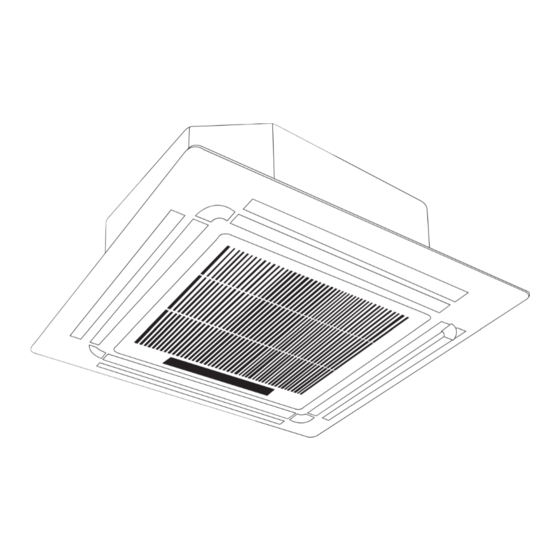
Compact Four-Way Cassette
R410a Models
Indoor Unit Model
MCA3U-12HRFN1-QRD0W
MCA3-18HRFN1-QRD0W
R32 Models
Indoor Unit Model
MCA3U-12HRFNX-QRD0W
MCA3-18HRFNX-QRD0W
Outdoor Unit Model
MOB30U-12HFN1-QRD0W
MOB30U-18HFN1-QRD0W
Outdoor Unit Model
MOB30U-12HFN8-QRD0W
MOB30U-18HFN8-QRD0W
Advertisement
Table of Contents

Related Manuals for Midea MCA3U-12HRFN1-QRD0W


Summary of Contents for Midea MCA3U-12HRFN1-QRD0W
- Page 1 Installation Manual Compact Four-Way Cassette R410a Models Indoor Unit Model Outdoor Unit Model MCA3U-12HRFN1-QRD0W MOB30U-12HFN1-QRD0W MCA3-18HRFN1-QRD0W MOB30U-18HFN1-QRD0W R32 Models Indoor Unit Model Outdoor Unit Model MCA3U-12HRFNX-QRD0W MOB30U-12HFN8-QRD0W MCA3-18HRFNX-QRD0W MOB30U-18HFN8-QRD0W...
-
Page 2: Table Of Contents
Table of Contents Installation Manual Accessories ..........Safety Precautions ......Installation Overview ....... 4 Indoor Unit Installation ......a. Indoor Unit Parts ..........07 b. Indoor Unit Installation Instructions ..08 5 Outdoor Unit Installation ......a. Outdoor Unit Installation Instructions ....11 b. - Page 3 Refrigerant Piping Connection ....a. Notes on Pipe Length and Elevation ....16 b. Refrigerant Piping Connection Instructions ..17 Caution: Risk of fire 8 Wiring (for R32 refrigerant ony ) ..........a. Outdoor Unit Wiring ......19 b. Indoor Unit Wiring ......20 c.
-
Page 4: Accessories
Accessories The air conditioning system comes with the following accessories. Use all of the installation parts and accessories to install the air conditioner. Improper installation may result in water leakage, electrical shock and fire, or cause the equipment to fail. Name Shape Quantity... -
Page 5: Safety Precautions
Safety Precautions Read Safety Precautions Before Installation Incorrect installation due to ignoring instructions can cause serious damage or injury. The seriousness of potential damage or injuries is classified as either a WARNING or CAUTION. Failure to observe a warning may result in death. The appliance must be installed in accordance with national regulations. -
Page 6: Installation Overview
Installation Overview INSTALLATION ORDER Install the indoor unit Install the outdoor unit Install the drainpipe (Page 7) (Page 11) (Page 14) Connect the wires Connect the refrigerant pipes Pressure test & Evacuate (Page 23) (Page 19) (Page 16) Install the fr ont panel Service Documents Perform a test run... - Page 7 Indoor Unit Installation Indoor Unit Parts Drain pump (within indoor unit) Drain pipe Air outlet Air inlet Front grille Louver Display panel Refrigerant pipe Fig. 4.1 Safety Precautions CAUTION WARNING • Install the indoor and outdoor units, cables and • Securely install the indoor unit on a structure that wires at least 1m from televisions or radios can sustain its weight.
- Page 8 Indoor Unit Installation Instructions CAUTION NOTE: Panel installation should be done after piping and wiring. DO NOT install the unit in the following locations: Step 1: Select installation location The indoor unit should be installed in a location that In areas with oil drilling or fracking meets the following requirements: In areas with caustic gases in the air, such as near ...
- Page 9 Table 4.1: Distance from ceiling relative to height of indoor unit Length of B mm MODEL Length of A mm Step 2: Hang indoor unit. 1. Use the included paper template to cut a rectangular hole in the ceiling, leaving at least 1m on all sides. The hole will be 60x60cm big.
- Page 10 5. Mount the indoor unit. You will need two people to NOTE: Ensure that the indoor unit is level. The unit is lift and secure it. Insert suspension bolts into the unit’ s equipped with a built-in drain pump and float switch. hanging holes (See Fig.
- Page 11 Outdoor Unit Installation Outdoor Unit Installation Instructions Step 1: Select installation location. If the location is exposed to strong winds (for example: near a seaside), the unit must be placed The outdoor unit should be installed in the location that against the wall to shelter it from the wind.
- Page 12 Fig. 5.4 Fig. 5.6 Fig. 5. More than 60cm Fig. 5.5 Table 5.1: Length Specifications of Split Type Outdoor Unit (unit: mm) Outdoor Unit Dimensions Mounting Dimensions W x H x D Distance A Distance B 800x333x554 800x333x554 946x410x810 (Twin Only) NOTE Since the units cent er of gravity is not at its physical center take care when lifting it with sling s .
-
Page 13: Outdoor Unit Installation
NOTE: The minimum distance between the outdoor Notes On Drilling Hole In Wall unit and walls described in the installation guide does not apply to airtight rooms. Be sure to keep the unit You must drill a hole in the wall for the refrigerant piping, unobstructed in at least two of the three directions (M, and the signal cable that will connect the indoor and N, P) (See Fig. -
Page 14: Drainpipe Installation
Drainpipe Installation The drainpipe is used to drain water from the unit. NOTE ON DRAINPIPE INSTALLATION Improper installation may cause unit and property damage. • When using an extended drainpipe, tighten the indoor connection with an additional protection tube to prevent it from pulling loose. CAUTION •... - Page 15 3. Using a 65-mm core drill, drill a hole in the wall. Make NOTE: When drilling the wall hole, make sure to avoid sure that the hole is drilled at a slight downward angle, wires, plumbing, and other sensitive components. so that the outdoor end of the hole is lower than the indoor end by about 12mm .
-
Page 16: Refrigerant Piping Connection
Refrigerant Piping Connection Table 7.1: The Maximum Length And Drop Height Safety Precautions Based on Models. (Unit: meters) Capacity Length of Maximum drop WARNING piping height Code • All field piping must be completed by a licensed technician and must comply with the local and national regulations. -
Page 17: Refrigerant Piping Connection Instructions
Table 7.2 Permitted length Step 2: Remove burrs. Total piping length 18K+18K L+Max Burrs can affect the gas-tight seal of refrigerant (L1, L2) piping connection. They must be completely removed. (farthest distance Piping L1,L2 Hold the pipe at a downward angle to prevent from the line pipe length branch) - Page 18 Step 4: Connect pipes Connect the copper pipes to the indoor unit first, then Table 7.3: PIPING EXTENSION BEYOND FLARE FORM connect it to the outdoor unit. You should first connect the low-pressure pipe, then the high-pressure pipe. Pipe Tightening Flare dimension (A) Flare shape torque...
-
Page 19: Wiring
Wiring NOTE: The fuse is made of ceramic. Safety Precautions TAKE NOTE OF FUSE SPECIFICATIONS WARNING The air conditioner’s circuit board(PCB) is designed with a fuse to provide overcurrent • Be sure to disconnect the power supply before protection. The speci cations of the fuse are working on the unit. -
Page 20: Indoor Unit Wiring
b. Using wire strippers, strip the rubber jacket from both ends of signal cable to reveal about 15cm Control box of the wires inside. c. Strip the insulation from the ends of the wires. d. Using a wire crimper, crimp u-lugs on the ends of the wires. -
Page 21: Power Specifications
Power Specifications Indoor Power Supply Specifications MODEL PHASE 1 Phase 1 Phase POWER FREQUENCY 220-240V 220-240V AND VOLT CIRCUIT BREAKER/ FUSE(A) Outdoor Inverter Power Supply Specifications MODEL Phase 1 Phase 1 Phase 1 Phase POWER FREQUENCY 220-240V 220-240V 220-240V AND VOLT CIRCUIT BREAKER/ FUSE(A) Outdoor 3 Phase Inverter Power Supply Specifications... -
Page 22: Wiring Diagram
Wiring Diagrams MCA3U-12HRFN1-QRD0W... - Page 23 MCA3U-12HRFN1-QRD0W MCA3-18HRFN1-QRD0 Page 22...
- Page 24 Pressure Test Instructions Systems are pressure tested to ensure they are: Safe – for this test a pressure above the system’s maximum allowable pressure (PS i ) is used Leak tight – this test is at PS i . Pressure testing is hazardous and should be carried out carefully: The nitrogen used for pressure testing is an asphyxiant, so the area around the system should be well-ventilated High pressures are used, so all non-essential personal should be evacuated...
- Page 25 Air Evacuation 4. Turn on the vacuum pump to evacuate the system. Safety Precautions 5. Run the vacuum for at least 15 minutes, or until the Gauge reads -76cmHG (-1x10⁵Pa). 6. Close the Low Pressure side of the manifold gauge, and CAUTION turn off the vacuum pump.
- Page 26 Note On Adding Refrigerant CAUTION • Refrigerant charging must be performed after wiring, vacuuming and the leak test. • DO NOT exceed the maximum allowable quantity of refrigerant or overcharge the system. Doing so can damage or impact the unit’ s function. •...
-
Page 27: Panel Installation
Panel Installation Step 3: Install the panel CAUTION Align the front panel to the main body, taking into account the position of the piping and drain sides. DO NOT place the panel facedown on the floor, against Hang the four latches of the decorative panel to the a wall, or on uneven surfaces. - Page 28 Remove foam stops from inside the fan. Close the front grille. Attach the side of the front grille to the panel. Fasten the installation covers at all four corners by pushing them inwards. (See Fig.10.6) Connect the display panel cable to the corresponding wire on the main body.
-
Page 29: Dip Switches
Dip Switches & Controller Dip Switches Definition Anti Cold Draft Fan motor power request Auto Restart after power Fault S1, S2 Unit Addresses Master Slave Temperature compensation Controller INSTALLATION METHOD Insert of the mainboard CN40 8. Turbo/Auxiliary Heat function indicator 1. -
Page 30: Test Run
Test Run Check to see that the drainage system is Before Test Run unimpeded and draining smoothly. g. Ensure there is no vibration or abnormal noise A test run must be performed after the entire system has during operation. been completely installed. Confirm the following points 5. - Page 31 Servicing Info (Required for the units adopt R32 Refrigerant only) 1. Checks to the area Prior to beginning work on systems containing flammable refrigerants, safety checks are necessary to ensure that the risk of ignition is minimised. For repair to the refrigerating system, the following precautions shall be complied with prior to conducting work on the system.
- Page 32 the charge size is in accordance with the room size within which the refrigerant containing parts are installed; the ventilation machinery and outlets are operating adequately and are not obstructed; if an indirect refrigerating circuit is being used, the secondary circuits shall be checked for the presence of refrigerant;...
- Page 33 11. Repair to intrinsically safe components Do not apply any permanent inductive or capacitance loads to the circuit without ensuring that this will not exceed the permissible voltage and current permitted for the equipment in use. Intrinscially safe components are the only types that can be worked on while live in the presence of a flammable atmosphere.
- Page 34 When the final OFN charge is used, the system shall be vented down to atmospheric pressure to enable work to take place. This operation is absolutely vital if brazing operations on the pipe-work are to take place. Ensure that the outlet for the vacuum pump is not closed to any ignition sources and there is ventilation available.
- Page 35 18. Labelling Equipment shall be labelled stating that it has been de-commissioned and emptied of refrigerant. The label shall be dated and signed. Ensure that there are labels on the equipment stating the equipment contains flammable refrigerant. 19. Recovery When removing refrigerant from a system, either for service or decommissioning, it is recommended good practice that all refrigerants are removed safely.
- Page 36 Step 15: Complete your warranty card document and e-mail this with dated photo of outdoor serial number to: warranty@fgeuropeuk.co.uk (Auto Restart) Note: Installation videos can also be found on the Midea UK YouTube channel. Please contact your Midea support team if you have any issues during the installation and commissioning process. Tel: 02074 092009 E-Mail: technical@fgeuropeuk.co.uk Indoor...
- Page 37 Display Board & Fault Codes Icon explanation of indoor display board Page 3 6 ...
- Page 38 Service Documents Mi Indoor Maintenance Checklist 17 Old Park Lane, London, W1K 1QT Tel: + 44 (0) 2074 092009 Customer Contact Information Company Name: Contact Name: Contact Number: E-Mail Address: Site Reference Date of Visit: Indoor Details Location Served Model No. Serial No.
- Page 39 Mi Outdoor Maintenance Checklist 17 Old Park Lane, London, W1K 1QT Tel: + 44 (0) 2074 092009 Customer Contact Information Company Name: Contact Name: Contact Number: E-Mail Address: Site Reference Date of Visit: Outdoor Details Location Served Model No. Serial No. 3 ☐...
- Page 40 Mi Commissioning & Installation Checklist 17 Old Park Lane, London, W1K 1QT Tel: + 44 (0) 2074 092009 Customer Contact Information Company Name: Contact Name: Contact Number: E-Mail Address: Site Reference Date of Visit: Site Address County/Region: Postcode: System Details Indoor Model No.
- Page 41 WARRANTY CLAIM REQUEST FORM 17 Old Park Lane, London, W1K 1QT Tel: + 44 (0) 2074 092009 Once this from is completed please return to: warranty@fgeuropeuk.co.uk Customer Contact Information Company Name: Contact Name: Contact Number: E-Mail Address: Site Reference: Date: Parts to Be Claimed Model No.
- Page 42 17 Old Park Lane, London, W1K 1QT Tel: + 44 (0) 2074 092009...