Table of Contents
Advertisement
MCAC-UTSM-2008-11
Contents
Part 1 General Information ..................................................................................................... 1
Part 2 Indoor Units .................................................................................................................. 7
Part 3 Outdoor Units ............................................................................................................. 88
Part 4 Installation ................................................................................................................ 127
Part 5 Control ...................................................................................................................... 136
※The specifications, designs, and information in this book are subject to change without notice for
product improvement.
Contents
i
Advertisement
Chapters
Table of Contents

Related Manuals for Midea MOU-12HN1


Summary of Contents for Midea MOU-12HN1
- Page 1 MCAC-UTSM-2008-11 Contents Part 1 General Information ..................... 1 Part 2 Indoor Units ........................7 Part 3 Outdoor Units ......................88 Part 4 Installation ........................ 127 Part 5 Control ........................136 ※The specifications, designs, and information in this book are subject to change without notice for product improvement.
-
Page 3: Table Of Contents
MCAC-UTSM-2008-11 General Information Part 1 General Information 1. Model Names of Indoor/Outdoor Units ...... 2 2. External Appearance ..........3 2.1 Indoor Units ................. 3 2.2 Outdoor Units................4 3. Nomenclature ............. 5 4. Features ..............6 General Information... -
Page 4: Model Names Of Indoor/Outdoor Units
Model Names of Indoor/Outdoor Units MCAC-UTSM-2008-11 1. Model Names of Indoor/Outdoor Units Outdoor unit model Power supply (V-ph-Hz) Compressor type Compressor brand Matched indoor units model MCA-12HRN1 MOU-12HN1 220~240-1-50 ROTARY MIDEA-TOSHIBA MUB-12HRN1 MCA-18HRN1 MOUA-18HN1 220~240-1-50 ROTARY MIDEA-TOSHIBA MUB-18HRN1 MCC-24HRN1 MOUA-24HN1... -
Page 5: External Appearance
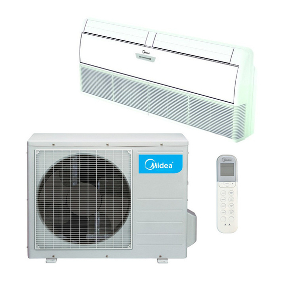
MCAC-UTSM-2008-11 External Appearance 2. External Appearance 2.1 Indoor Units Four-way cassette type Four-way cassette type (compact) Ceiling & floor type Ceiling & floor type General Information... -
Page 6: Outdoor Units
External Appearance MCAC-UTSM-2008-11 2.2 Outdoor Units 12,000Btu/h 18,000Btu/h 30,000~36,000Btu/h 24,000Btu/h 48,000Btu/h 60,000Btu/h General Information... -
Page 7: Nomenclature
Indoor Unit Type T Duct H High Static Pressure Duct C Cassette U Ceiling & Floor Midea 3.2 Outdoor Unit M O U A - 48 H N1 - R Power Supply R 380V~415V, 3N, 50Hz -- 220~240V, 1N, 50Hz... -
Page 8: Features
Features MCAC-UTSM-2008-11 4. Features 1. High quality coils: The coil is constructed of advanced inner grooved copper tube and aluminum fins. 2. Anti-rust, 500 hours salt spray test. 3. Low operation sound level: Well-known stable and quiet running fan motor. 4. -
Page 9: Part 2 Indoor Units
MCAC-UTSM-2008-11 Indoor Units Part 2 Indoor Units Four-way Cassette Type (Compact) ......8 Four-way Cassette Type..........21 Ceiling & Floor Type ............. 53 Indoor Units... -
Page 10: Four-Way Cassette Type (Compact)
Four-way Cassette Type (Compact) MCAC-UTSM-2008-11 Four-way Cassette Type (Compact) 1. Features ...................... 9 2. Specifications ..................10 3. Dimensions ....................11 4. Service Space ..................11 5. Wiring Diagram ..................12 6. Air Velocity and Temperature Distributions .......... 13 7. Capacity Tables ..................14 8. -
Page 11: Features
MCAC-UTSM-2008-11 Features 1. Features (1) Low operation noise ---Streamline plate ensures quietness ---Creates natural and comfortable environment (2) Efficient cooling ---Equal, fast and wide—range cooling (3) The adoption of the most advanced 3-Dimensional Screw Fan ---Reduces the air resistance passing through ---Smoothes the air flow ---Makes air speed distribution to the heat exchange uniform (4) Improvement for easy installation and maintenance... -
Page 12: Specifications
Specifications MCAC-UTSM-2008-11 2. Specifications Model MCA-12HRN1 MCA-18HRN1 Code 220042002960 220042001870 Power supply V-ph-Hz 220~240-1-50 220~240-1-50 Capacity Cooling Input 1100 1900 Capacity Heating Input 1050 1900 Model YDK45-4F YDK45-4F Brand Welling Welling Indoor fan motor Input 56.7/51.5/44.4 56.7/51.5/44.4 Capacitor 1.5uF/450V 2.5uF/450V Speed(Hi/Mi/Lo) r/min 930/845/680... -
Page 13: Dimensions
MCAC-UTSM-2008-11 Dimensions 3. Dimensions 4. Service Space Indoor Units... -
Page 14: Wiring Diagram
Wiring Diagram MCAC-UTSM-2008-11 5. Wiring Diagram Indoor Units... -
Page 15: Air Velocity And Temperature Distributions
MCAC-UTSM-2008-11 Air Velocity and Temperature Distributions 6. Air Velocity and Temperature Distributions Airflow velocity Temperature Indoor Units... -
Page 16: Capacity Tables
Capacity Tables MCAC-UTSM-2008-11 7. Capacity Tables 7.1 Cooling Capacity MCA-12HRN1 Cooling Outdoor conditions (DB) Indoor Conditions (kW) 21ºC 28ºC 35ºC 43ºC 3.30 3.14 2.98 2.85 21/15ºC DB/WB 2.44 2.41 2.38 2.39 Input 0.91 0.99 1.03 1.07 3.39 3.23 3.07 2.88 24/17ºC DB/WB 2.54 2.52... - Page 17 MCAC-UTSM-2008-11 Capacity Tables 7.2 Heating Capacity MCA-12HRN1 Heating Outdoor conditions Indoor Conditions (DB) (kW) 24/18ºC DB/WB 7/6ºC DB/WB 2/1ºC DB/WB -5/-6ºC DB/WB 5.20 4.20 3.44 3.12 15ºC 1.13 0.98 0.84 0.79 Input 5.04 3.24 3.04 4.00 20ºC 1.24 0.92 0.85 Input 1.05 4.72...
-
Page 18: Electric Characteristics
Electric Characteristics MCAC-UTSM-2008-11 8. Electric Characteristics Indoor Units Power Supply Indoor Fan Motor Model Voltage Min. Max. MCA-12HRN1 220-240V 198V 254V 0.33 0.045 0.264 MCA-18HRN1 220-240V 198V 254V 0.33 0.045 0.264 Remark: MCA: Min. Current Amps. (A) MFA: Max. Fuse Amps. (A) KW: Fan Motor Rated Output (kW) FLA: Full Load Amps. -
Page 19: Exploded View
MCAC-UTSM-2008-11 Exploded View 10. Exploded View MCA-12HRN1 MCA-18HRN1 10.5 Part Name Quantity Part Name Quantity Drainage pan ass'y E-Part box cover Centrifugal fan Drain pump Holder Installation bracket Drain pump Evaporator fixing hanger Right clapboard ass'y Motor Partition board Motor base Evaporator fixing board ass'y Base ass'y Evaporator ass'y... -
Page 20: Accessories
Accessories MCAC-UTSM-2008-11 11. Accessories Name Shape Quantity 1. Expansible hook Installation fittings 2. Installation hook 3. Installation paper board 4. Out-let pipe sheath 5. Out-let pipe clasp Drainpipe Fittings 6. Tightening band 7. Drain joint 8. Remote controller Remote controller & Its 9. -
Page 21: Field Wiring
MCAC-UTSM-2008-11 Field Wiring 13. Field Wiring MCA-12HRN1 Indoor Units... - Page 22 Field Wiring MCAC-UTSM-2008-11 MCA-18HRN1 Indoor Units...
-
Page 23: Four-Way Cassette Type
MCAC-UTSM-2008-11 Four-way Cassette Type Four-way Cassette Type 1. Features ....................22 2. Specifications ..................24 3. Dimensions ....................27 4. Service Space ..................28 5. Wiring Diagrams ..................29 6. Air Velocity and Temperature Distributions .......... 31 7. Capacity Tables ..................32 8. -
Page 24: Features
Features MCAC-UTSM-2008-11 1. Features (1) Ultra thin machine body to easy installation and maintenance. 24K:230mm, 30-48K:300mm. (2) Different color panels to choose: White, Gray, Blue, Black (3) The swing angle of the first louver are 40~42 degrees and the second louver are 37~38 degrees. (4) 4 speeds available, optional super high fan speed design, suitable for the large building over 3m high. - Page 25 MCAC-UTSM-2008-11 Features (7) Stylish design is harmonious with any interior decoration and creates and elegant environment. (8) Built-in water pump with 750mm pumping head. (9) Fresh air makes life more healthy and comfortable. Indoor Units...
-
Page 26: Specifications
Specifications MCAC-UTSM-2008-11 2. Specifications Model MCC-24HRN1 MCC-30HRN1 Code 220042500390 220042600250 Power supply V-ph-Hz 220~240-1-50 220~240-1-50 Capacity Cooling Input 2700 3500 Capacity Heating Input 2800 3600 Model YDK80-6E YDK90-6E Brand Welling Welling Indoor fan motor Input 120/110/100/90 165/143/116/100 Capacitor 3.5uF/450V 3.5uF/450V Speed(Hi/Mi/Lo) r/min 800/670/550/400... - Page 27 MCAC-UTSM-2008-11 Specifications Model MCC-30HRN1-R MCC-36HRN1 Code 220042600270 220042700210 Power supply V-ph-Hz 380~415-3-50 220~240-1-50 Capacity 10.5 Cooling Input 3500 3850 Capacity 12.0 Heating Input 3700 4050 Model YDK90-6E YDK90-6E Brand Welling Welling Indoor fan motor Input 165/143/116/100 165/143/116/100 Capacitor 3.5uF/450V 3.5uF/450V Speed(Hi/Mi/Lo) r/min 840/770/640/550...
- Page 28 Specifications MCAC-UTSM-2008-11 Model MCC-36HRN1-R MCC-48HRN1-R Code 220042700230 220042800310 Power supply V-ph-Hz 380~415-3-50 380~415-3-50 Capacity 10.5 Cooling Input 4881 3850 Capacity 12.0 Heating Input 4941 4100 Model YDK90-6E YDK90-6E Brand Welling Welling Indoor fan motor Input 165/143/116/100 165/143/116/100 Capacitor 3.5uF/450V 3.5uF/450V Speed(Hi/Mi/Lo) r/min 840/770/640/550...
-
Page 29: Dimensions
MCAC-UTSM-2008-11 Dimensions 3. Dimensions 3.1 MCC-24HRN1 3.2 MCC-30HRN1 MCC-30HRN1-R MCC-36HRN1 MCC-36HRN1-R MCC-48HRN1-R Indoor Units... -
Page 30: Service Space
Service Space MCAC-UTSM-2008-11 4. Service Space The indoor unit should be installed in a location that meets the following requirements: ● There is enough room for installation and maintenance. ● The ceiling is horizontal, and its structure can endure the weight of the indoor unit. ●... -
Page 31: Wiring Diagrams
MCAC-UTSM-2008-11 Wiring Diagrams 5. Wiring Diagrams 5.1 MCC-24HRN1 MCC-30HRN1 MCC-36HRN1 Indoor Units... - Page 32 Wiring Diagrams MCAC-UTSM-2008-11 5.2 MCC-30HRN1-R MCC-36HRN1-R MCC-48HRN1-R Indoor Units...
-
Page 33: Air Velocity And Temperature Distributions
MCAC-UTSM-2008-11 Air Velocity and Temperature Distributions 6. Air Velocity and Temperature Distributions Airflow velocity Temperature Indoor Units... -
Page 34: Capacity Tables
Capacity Tables MCAC-UTSM-2008-11 7. Capacity Tables MCC-24HRN1 Cooling Cooling Outdoor conditions (DB) Indoor Conditions (kW) 21ºC 28ºC 35ºC 43ºC 7.31 6.96 6.60 6.32 21/15ºC DB/WB 5.41 5.36 5.28 5.31 Input 2.24 2.43 2.54 2.62 7.53 7.17 6.82 6.39 24/17ºC DB/WB 5.64 5.59 5.52... - Page 35 MCAC-UTSM-2008-11 Capacity Tables MCC-30HRN1 Cooling Cooling Outdoor conditions (DB) Indoor Conditions (kW) 21ºC 28ºC 35ºC 43ºC 9.27 8.82 8.37 8.01 21/15ºC DB/WB 6.86 6.79 6.70 6.73 Input 2.91 3.15 3.29 3.40 9.54 9.09 8.64 8.10 24/17ºC DB/WB 7.16 7.09 7.00 6.80 Input 3.08...
- Page 36 Capacity Tables MCAC-UTSM-2008-11 MCC-30HRN1-R Cooling Cooling Outdoor conditions (DB) Indoor Conditions (kW) 21ºC 28ºC 35ºC 43ºC 9.27 8.82 8.37 8.01 21/15ºC DB/WB 6.86 6.79 6.70 6.73 Input 2.91 3.15 3.29 3.40 9.54 9.09 8.64 8.10 24/17ºC DB/WB 7.16 7.09 7.00 6.80 Input 3.08...
- Page 37 MCAC-UTSM-2008-11 Capacity Tables MCC-36HRN1 Cooling Cooling Outdoor conditions (DB) Indoor Conditions (kW) 21ºC 28ºC 35ºC 43ºC 10.82 10.29 9.77 9.35 21/15ºC DB/WB 8.00 7.92 7.81 7.85 Input 3.20 3.47 3.62 3.73 11.13 10.61 10.08 9.45 24/17ºC DB/WB 8.35 8.27 8.16 7.94 Input 3.39...
- Page 38 Capacity Tables MCAC-UTSM-2008-11 MCC-36HRN1-R Cooling Cooling Outdoor conditions (DB) Indoor Conditions (kW) 21ºC 28ºC 35ºC 43ºC 10.82 10.29 9.77 9.35 21/15ºC DB/WB 8.00 7.92 7.81 7.85 Input 3.20 3.47 3.62 3.73 11.13 10.61 10.08 9.45 24/17ºC DB/WB 8.35 8.27 8.16 7.94 Input 3.39...
- Page 39 MCAC-UTSM-2008-11 Capacity Tables MCC-48HRN1-R Cooling Cooling Outdoor conditions (DB) Indoor Conditions (kW) 21ºC 28ºC 35ºC 43ºC 14.42 13.72 13.02 12.46 21/15ºC DB/WB 10.67 10.56 10.42 10.47 Input 4.05 4.39 4.59 4.73 14.84 14.14 13.44 12.60 24/17ºC DB/WB 11.13 11.03 10.89 10.58 Input 4.30...
-
Page 40: Electric Characteristics
Electric Characteristics MCAC-UTSM-2008-11 8. Electric Characteristics Indoor Units Power Supply Indoor Fan Motor Model Voltage Min. Max. MCC-24HRN1 220-240V 198V 254V 0.065 0.56 MCC-30HRN1 220-240V 198V 254V 0.955 0.090 MCC-30HRN1-R 380-415V 342V 418V 0.955 0.090 MCC-36HRN1 220-240V 198V 254V 0.955 0.090 MCC-36HRN1-R 380-415V... -
Page 41: Exploded View
MCAC-UTSM-2008-11 Exploded View 10. Exploded View 10.1 MCC-24HRN1 Indoor Units... - Page 42 Exploded View MCAC-UTSM-2008-11 Part Name Quantity Part Name Quantity Electricity control box coping I Motor Electricity control box coping II Base E-part box ass'y Wire clamp E-part box Panel Transformer Wire clamp Room temp. sensor ass'y Wire clip Motor capacitor Evaporator fixing hanger Main controller Water pump board...
- Page 43 MCAC-UTSM-2008-11 Exploded View 10.2 MCC-30HRN1 Indoor Units...
- Page 44 Exploded View MCAC-UTSM-2008-11 Part Name Quantity Part Name Quantity Electric control box head cover I Base pan seat Electric control box head cover II Base pan welded assembly Electric control box assembly of indoor Plate, wire unit Electric control box welded assembly Tandem, wire Voltage transformer Bipitch wire clip...
- Page 45 MCAC-UTSM-2008-11 Exploded View 10.3 MCC-30HRN1 -R Indoor Units...
- Page 46 Exploded View MCAC-UTSM-2008-11 Part Name Quantity Part Name Quantity Electric control box head cover I Base pan seat Electric control box head cover II Base pan welded assembly Electric control box assembly of indoor Plate, wire unit Electric control box welded assembly Tandem, wire Voltage transformer Bipitch wire clip...
- Page 47 MCAC-UTSM-2008-11 Exploded View 10.4 MCC-36HRN1 Indoor Units...
- Page 48 Exploded View MCAC-UTSM-2008-11 Part Name Quantity Part Name Quantity Electric control box head cover I Base pan seat Electric control box head cover II Base pan welded assembly Electric control box assembly of indoor Plate, wire unit Electric control box welded assembly Tandem, wire Voltage transformer Bipitch wire clip...
- Page 49 MCAC-UTSM-2008-11 Exploded View 10.5 MCC-36HRN1-R Indoor Units...
- Page 50 Exploded View MCAC-UTSM-2008-11 Part Name Quantity Part Name Quantity Electric control box head cover I Base pan seat Electric control box head cover II Base pan welded assembly Electric control box assembly of indoor Plate, wire unit Electric control box welded assembly Tandem, wire Voltage transformer Bipitch wire clip...
- Page 51 MCAC-UTSM-2008-11 Exploded View 10.6 MCC-48HRN1-R 3/3.2/3.3/3.4/3.5/3.6/3.7 33 Indoor Units...
- Page 52 Exploded View MCAC-UTSM-2008-11 Part Name Quantity Part Name Quantity Electricity control box coping I Chassis pillow Electricity control box coping II Chassis Ass'y Electric control assy subassembly Plate, wire E-part box Panel Transformer Plate, wire Indoor temp. sensor subassembly Bipitch wire clip Motor capacitor Fixing hanger, evaporator Main controller subassembly...
-
Page 53: Accessories
MCAC-UTSM-2008-11 Accessories 11. Accessories Name Shape Quantity 1. Expansible hook Installation Fittings 2. Installation hook 3. Installation paper board 4. Bolt M5 5. Connecting pipe group 6. Binding tape Tubing & Fittings 7.Soundproof/insulation sheath 8. Out-let pipe sheath 9. Out-let pipe clasp Drainpipe Fittings 10. -
Page 54: Field Wiring
Field Wiring MCAC-UTSM-2008-11 13. Field Wiring Indoor Units... - Page 55 MCAC-UTSM-2008-11 Ceiling & Floor Type Ceiling & Floor Type 1. Features ....................54 2. Specifications ..................55 3. Dimensions ....................59 4. Service Space................... 60 5. Wiring Diagrams ..................61 6. Air Velocity and Temperature Distributions........... 65 7. Capacity Tables ..................67 8.
-
Page 56: Features
Features MCAC-UTSM-2008-11 1. Features 1.1. New design, more modern and elegant appearance. 1.2. Convenient installation --The ceiling type can be easily installed into a corner of the ceiling even if the ceiling is very narrow --It is especially useful when installation of an air conditioner in the center of the ceiling is impossible due to a structure such as one lighting 1.3. -
Page 57: Specifications
MCAC-UTSM-2008-11 Specifications 2. Specifications Model MUB-12HRN1 MUB-18HRN1 Code 220042101900 220042101920 Power supply V-ph-Hz 220~240-1-50 220~240-1-50 Capacity Cooling Input 1200 1900 Capacity Heating Input 1130 1850 Model YSK25-6L YSK55-4L Brand Welling Welling Indoor fan motor Input 33.4/31.1/29.5 125/105/85 Capacitor 1.2uF/450V 2.5uF/450V Speed(Hi/Mi/Lo) r/min 756/666/592... - Page 58 Specifications MCAC-UTSM-2008-11 Model MUB-24HRN1 MUB-30HRN1 Code 220042101940 220044300050 Power supply V-ph-Hz 220~240-1-50 220~240-1-50 Capacity Cooling Input 2700 3750 Capacity Heating Input 2800 3500 Model YSK55-4L YSK80-4A Brand Welling Welling Indoor fan motor Input 125/105/85 143/122/110 Capacitor 2.5uF/450V 3.5uF/450V Speed(Hi/Mi/Lo) r/min 1310/1190/1040 1310/1210/1115 Number of rows...
- Page 59 MCAC-UTSM-2008-11 Specifications Model MUB-30HRN1 MUB-36HRN1 Code 220042102000 220044400160 Power supply V-ph-Hz 380~415-3-50 220~240-1-50 Capacity 10.5 Cooling Input 3750 3750 Capacity Heating Input 3500 3500 Model YSK80-4A YSK80-4A Brand Welling Welling Indoor fan motor Input 143/122/110 143/122/110 Capacitor 3.5uF/450V 3.5uF/450V Speed(Hi/Mi/Lo) r/min 1310/1210/1115 1310/1210/1115...
- Page 60 Specifications MCAC-UTSM-2008-11 Model MUB-36HRN1 MUB-48HRN1-R MUB-60HRN1-R Code 220042102020 220042102040 220042102060 Power supply V-ph-Hz 380~415-3-50 380~415-3-50 380~415-3-50 Capacity 10.5 Cooling Input 3750 4700 5578 Capacity Heating Input 3700 4731 5764 Model YSK80-4A YSK59-4D(×2) YSK59-4D(×2) Brand Welling Welling Welling Indoor fan Input 143/122/110 89.5/81.5/77.5 89.5/81.5/77.5...
-
Page 61: Dimensions
MCAC-UTSM-2008-11 Dimensions 3. Dimensions a. Wall mounting installation b. Ceiling installation Capacity (Btu/h) 12000-24000 30000-36000 1280 1195 48000-60000 1670 1070 1542 Note: The dimension of 12000Btu/h, 18000Btu/h and 24000Btu/h are the same. The dimension of 30000Btu/h and 36000Btu/h are the same. The dimension of 48000Btu/h and 60000Btu/h are the same. -
Page 62: Service Space
Service Space MCAC-UTSM-2008-11 4. Service Space Indoor Units... -
Page 63: Wiring Diagrams
MCAC-UTSM-2008-11 Wiring Diagrams 5. Wiring Diagrams 5.1 MUB-12HRN1 MUB-18HRN1 Indoor Units... - Page 64 Wiring Diagrams MCAC-UTSM-2008-11 5.2 MUB-24HRN1 MUB-30HRN1(1 phase) MUB-36HRN1(1 phase) Indoor Units...
- Page 65 MCAC-UTSM-2008-11 Wiring Diagrams 5.3 MUB-30HRN1(3 phase) MUB-36HRN1(3 phase) Indoor Units...
- Page 66 Wiring Diagrams MCAC-UTSM-2008-11 5.3 MUB-48HRN1-R MUB-60HRN1-R Indoor Units...
-
Page 67: Air Velocity And Temperature Distributions
MCAC-UTSM-2008-11 Air Velocity and Temperature Distributions 6. Air Velocity and Temperature Distributions Discharge angle 60° (CEILING) Airflow velocity Temperature Indoor Units... - Page 68 Air Velocity and Temperature Distributions MCAC-UTSM-2008-11 Discharge angle 60°(FLOOR) Temperature Airflow velocity Indoor Units...
-
Page 69: Capacity Tables
MCAC-UTSM-2008-11 Capacity Tables 7. Capacity Tables MUB-12HRN1 Cooling Cooling Outdoor conditions (DB) Indoor Conditions (kW) 21ºC 28ºC 35ºC 43ºC 3.30 3.14 2.98 2.85 21/15ºC DB/WB 2.44 2.41 2.38 2.39 Input 1.00 1.08 1.13 1.16 3.39 3.23 3.07 2.88 24/17ºC DB/WB 2.54 2.52 2.49... - Page 70 Capacity Tables MCAC-UTSM-2008-11 MUB-18HRN1 Cooling Cooling Outdoor conditions (DB) Indoor Conditions (kW) 21ºC 28ºC 35ºC 43ºC 5.46 5.19 4.93 4.72 21/15ºC DB/WB 4.04 4.00 3.94 3.96 Input 1.58 1.71 1.79 1.84 5.62 5.35 5.09 4.77 24/17ºC DB/WB 4.21 4.18 4.12 4.01 Input 1.67...
- Page 71 MCAC-UTSM-2008-11 Capacity Tables MUB-24HRN1 Cooling Cooling Outdoor conditions (DB) Indoor Conditions (kW) 21ºC 28ºC 35ºC 43ºC 7.31 6.96 6.60 6.32 21/15ºC DB/WB 5.41 5.36 5.28 5.31 Input 2.24 2.43 2.54 2.62 7.53 7.17 6.82 6.39 24/17ºC DB/WB 5.64 5.59 5.52 5.37 Input 2.38...
- Page 72 Capacity Tables MCAC-UTSM-2008-11 MUB-30HRN1 (1 phase) Cooling Cooling Outdoor conditions (DB) Indoor Conditions (kW) 21ºC 28ºC 35ºC 43ºC 9.27 8.82 8.37 8.01 21/15ºC DB/WB 6.86 6.79 6.70 6.73 Input 3.11 3.38 3.53 3.64 9.54 9.09 8.64 8.10 24/17ºC DB/WB 7.16 7.09 7.00 6.80...
- Page 73 MCAC-UTSM-2008-11 Capacity Tables MUB-30HRN1 (3 phase) Cooling Cooling Outdoor conditions (DB) Indoor Conditions (kW) 21ºC 28ºC 35ºC 43ºC 9.27 8.82 8.37 8.01 21/15ºC DB/WB 6.86 6.79 6.70 6.73 Input 3.11 3.38 3.53 3.64 9.54 9.09 8.64 8.10 24/17ºC DB/WB 7.16 7.09 7.00 6.80...
- Page 74 Capacity Tables MCAC-UTSM-2008-11 MUB-36HRN1 (1 phase) Cooling Cooling Outdoor conditions (DB) Indoor Conditions (kW) 21ºC 28ºC 35ºC 43ºC 10.82 10.29 9.77 9.35 21/15ºC DB/WB 8.00 7.92 7.81 7.85 Input 3.11 3.38 3.53 3.64 11.13 10.61 10.08 9.45 24/17ºC DB/WB 8.35 8.27 8.16 7.94...
- Page 75 MCAC-UTSM-2008-11 Capacity Tables MUB-36HRN1 (3 phase) Cooling Cooling Outdoor conditions (DB) Indoor Conditions (kW) 21ºC 28ºC 35ºC 43ºC 10.82 10.29 9.77 9.35 21/15ºC DB/WB 8.00 7.92 7.81 7.85 Input 3.11 3.38 3.53 3.64 11.13 10.61 10.08 9.45 24/17ºC DB/WB 8.35 8.27 8.16 7.94...
- Page 76 Capacity Tables MCAC-UTSM-2008-11 MUB-48HRN1-R Cooling Cooling Outdoor conditions (DB) Indoor Conditions (kW) 21ºC 28ºC 35ºC 43ºC 14.42 13.72 13.02 12.46 21/15ºC DB/WB 10.67 10.56 10.42 10.47 Input 3.90 4.23 4.42 4.56 14.84 14.14 13.44 12.60 24/17ºC DB/WB 11.13 11.03 10.89 10.58 Input 4.14...
- Page 77 MCAC-UTSM-2008-11 Capacity Tables MUB-60HRN1-R Cooling Cooling Outdoor conditions (DB) Indoor Conditions (kW) 21ºC 28ºC 35ºC 43ºC 16.48 15.68 14.88 14.24 21/15ºC DB/WB 12.20 12.07 11.90 11.96 Input 4.63 5.02 5.24 5.41 16.96 16.16 15.36 14.40 24/17ºC DB/WB 12.72 12.60 12.44 12.10 Input 4.91...
-
Page 78: Electric Characteristics
Electric Characteristics MCAC-UTSM-2008-11 8. Electric Characteristics Indoor Units Power Supply Indoor Fan Motor Model Voltage Min. Max. MUB-12HRN1 220-240V 198V 254V 0.025 0.145 MUB-18HRN1 220-240V 198V 254V 0.71 0.055 0.57 MUB-24HRN1 220-240V 198V 254V 0.71 0.055 0.57 MUB-30HRN1 220-240V 198V 254V 0.79 0.08... -
Page 79: Exploded View
MCAC-UTSM-2008-11 Exploded View 10. Exploded View 10.1 MUB-12HRN1 Part Name Quantity Part Name Quantity Filter Evaporator ass'y Grille clamp Installation board Grille Foam ass'y Grille clamp Foam ass'y Grille strengthening rib Evaporator Left support Volute shell Foam ass'y Grille lock Support board Plastic fan Evaporator right clapboard... - Page 80 Exploded View MCAC-UTSM-2008-11 10.2 MUB-18HRN1 Part Name Quantity Part Name Quantity Filter Evaporator ass'y Grille clamp Installation board Grille Foam ass'y Grille hang Foam ass'y Grille strengthening rib Evaporator Left support Volute shell Foam ass'y Grille lock Support board Plastic fan Evaporator right clapboard Motor clamp Evaporator left clapboard...
- Page 81 MCAC-UTSM-2008-11 Exploded View 10.3 MUB-24HRN1 Part Name Quantity Part Name Quantity Filter Evaporator ass'y Grille clamp Installation board Grille Foam ass'y Grille hang Foam ass'y Grille strengthening rib Evaporator Left support Volute shell Foam ass'y Grille lock Support board Plastic fan Evaporator right clapboard Motor clamp Evaporator left clapboard...
- Page 82 Exploded View MCAC-UTSM-2008-11 10.4 MUB-30HRN1 MUB-36HRN1(1 phase) Part Name Quantity Part Name Quantity Filter Evaporator ass'y Grille clamp Installation board Grille Foam ass'y Grille clamp Foam ass'y Grille strengthening rib Evaporator Left support Volute shell Foam ass'y Grille lock Support board Plastic fan Evaporator right clapboard Motor clamp...
- Page 83 MCAC-UTSM-2008-11 Exploded View 10.5 MUB-30HRN1 MUB-36HRN1(3 phase) Part Name Quantity Part Name Quantity Filter Evaporator ass'y Grille clamp Installation board Grille Foam ass'y Grille clamp Foam ass'y Grille strengthening rib Evaporator Left support Volute shell Foam ass'y Grille lock Support board Plastic fan Evaporator right clapboard Motor clamp...
- Page 84 Exploded View MCAC-UTSM-2008-11 10.6 MUB-48HRN1-R 31.1 Part Name Quantity Part Name Quantity Grille ass'y Volute shell Motor clamp Middle beam Motor clamp E-part box cover Filter bracket E-part box ass'y Installation board 24.1 Main controller ass'y Installation board 24.2 Motor capacitor Filter bracket 24.3 Wire joint...
- Page 85 MCAC-UTSM-2008-11 Exploded View 10.7 MUB-60HRN1-R Part Name Quantity Part Name Quantity Grille ass'y Volute shell Motor clamp Middle beam Motor clamp E-part box cover Filter bracket E-part box ass'y Installation board 24.1 Main controller ass'y Installation board 24.2 Motor capacitor Filter bracket 24.3 Wire joint...
-
Page 86: Accessories
Accessories MCAC-UTSM-2008-11 11. Accessories Name Shape Quantity 1.Hook Installation fittings 2.Hanging arm 3. Remote controller 4. Remote controller holder Remote controller & Its Holder 5. Mounting screw(ST2.9×10-C-H) 6. Alkaline dry batteries (AM4) 7. Owner's manual Others 8. Installation manual 9. Remote controller manual 12. -
Page 87: Field Wiring
MCAC-UTSM-2008-11 Field Wiring 13. Field Wiring MUB-12HRN1 MUB-18HRN1 Indoor Units... - Page 88 Field Wiring MCAC-UTSM-2008-11 MUB-24HRN1 MUB-30HRN1 MUB-36HRN1(1 phase) Indoor Units...
- Page 89 MCAC-UTSM-2008-11 Field Wiring MUB-30HRN1 MUB-36HRN1(3 phase) MUB-48HRN1-R MUB-60HRN1-R Indoor Units...
-
Page 90: Part 3 Outdoor Units
Outdoor Units MCAC-UTSM-2008-11 Part 3 Outdoor Units 1. Specifications ............89 2. Dimensions ............... 94 3. Service Space ............99 4. Piping Diagrams ............. 100 5. Wiring Diagrams ............. 103 6. Electric Characteristics .......... 109 7. Operation Limits ............. 109 8. -
Page 91: Specifications
MCAC-UTSM-2008-11 Specifications 1. Specifications Model MOU-12HN1 MOUA-18HN1 Code 220075100110 220075200490 Power supply V-ph-Hz 220~240-1-50 220~240-1-50 Max. input consumption 1500 2400 Max. input current 10.9 Starting current Model PA140X2C-4FT PA225X2CS-4KU1 Type ROTARY ROTARY Brand MIDEA-TOSHIBA MIDEA-TOSHIBA Supplier MIDEA-TOSHIBA MIDEA-TOSHIBA Capacity Btu/h... - Page 92 Power supply V-ph-Hz 220~240-1-50 220~240-1-50 Max. input consumption 3300 4620 Max. input current Starting current Model PA290X3CS-4MU1 C-SBN301H5D Type ROTARY SCROLL Brand MIDEA-TOSHIBA SANYO Supplier MIDEA-TOSHIBA SANYO Capacity Btu/h 24600 33438 Compressor Input 2430 3650 Rated current(RLA) 11.4 17.65 Locked rotor Amp(LRA)
- Page 93 MCAC-UTSM-2008-11 Specifications Model MOU-30HN1-R MOU-36HN1 Code 220075400020 220075500670 Power supply V-ph-Hz 380~415-3-50 220~240-1-50 Max. input consumption 4620 4620 Max. input current Starting current Model C-SBN303H8D C-SBN301H5D Type SCROLL SCROLL Brand SANYO SANYO Supplier SANYO(Dalian) SANYO Capacity Btu/h 33438 33438 Compressor Input 3650 3650...
- Page 94 Specifications MCAC-UTSM-2008-11 Model MOU-36HN1-R MOUA-48HN1-R Code 220075500680 220075700040 Power supply V-ph-Hz 380~415-3-50 380~415-3-50 Max. input consumption 4620 5870 Max. input current 10.7 Starting current Model C-SBN303H8D JT160G-P8Y1 Type SCROLL SCROLL Brand SANYO DAIKIN Supplier SANYO(Dalian) DAIKIN Capacity Btu/h 33438 49098.7 Compressor Input 3650...
- Page 95 MCAC-UTSM-2008-11 Specifications Model MOUA-60HN1-R Code 220075800650 Power supply V-ph-Hz 380~415-3-50 Max. input consumption 7500 Max. input current 12.8 Starting current Model C-SBN453H8D Type SCROLL Brand SANYO Supplier Dalian SANYO Compressor Co., Ltd. Capacity Btu/h 55956.8 Compressor Input 5750 Rated current(RLA) 9.77 Locked rotor Amp(LRA) Thermal protector...
-
Page 96: Dimensions
Dimensions MCAC-UTSM-2008-11 2. Dimensions 2.1 MOU-12HN1 Outdoor Units... - Page 97 MCAC-UTSM-2008-11 Dimensions 2.2 MOUA-18HN1 Outdoor Units...
- Page 98 Dimensions MCAC-UTSM-2008-11 2.3 MOUA-24HN1 Outdoor Units...
- Page 99 MCAC-UTSM-2008-11 Dimensions 2.4 MOU-30HN1 MOU-30HN1-R MOU-36HN1 MOU-36HN1-R Outdoor Units...
- Page 100 Dimensions MCAC-UTSM-2008-11 2.5 MOUA-48HN1-R MOUA-60HN1-R Outdoor Units...
-
Page 101: Service Space
MCAC-UTSM-2008-11 Service Space 3. Service Space Obstacle (Wall or obstacle) Air inlet >30cm Fix with bolt Air inlet Maintain channel >60cm Air outlet Deep foundation Necessary width 600mm is necessary between 2 outdoor units Outdoor Units... -
Page 102: Piping Diagrams
Piping Diagrams MCAC-UTSM-2008-11 4. Piping Diagrams 4.1 MOU-12HN1 Indoor units Outdoor unit condenser temp. sensor Check valve evaporator temp. sensor 4-way valve filter stop valve Throttle capiliary room temp. sensor stop valve compressor 4.2 MOUA-18HN1 Indoor units Outdoor unit condenser temp. sensor filter evaporator temp. - Page 103 MCAC-UTSM-2008-11 Piping Diagrams 4.3 MOUA-24HN1 Indoor units Outdoor unit condenser temp. sensor filter evaporator temp. sensor 4-way valve stop valve Throttle capiliary room temp. sensor stop valve compressor 4.4 MOU-30HN1 MOU-36HN1 MOU-30HN1-R MOU-36HN1-R Indoor units Outdoor unit condenser temp. sensor Check valve evaporator temp.
-
Page 104: Outdoor Units
Piping Diagrams MCAC-UTSM-2008-11 4.5 MOUA-48HN1-R Indoor units Outdoor unit condenser temp. sensor filter evaporator temp. sensor 4-way valve stop valve High pressure switch room temp. sensor Throttle capiliary ambient temp. sensor stop valve Low pressure switch Discharge temp.sensor low pressure receiver compressor 4.6 MOUA-60HN1-R Indoor units... -
Page 105: Wiring Diagrams
MCAC-UTSM-2008-11 Wiring Diagrams 5. Wiring Diagrams 5.1 MOU-12HN1 Outdoor Units... - Page 106 Wiring Diagrams MCAC-UTSM-2008-11 5.2 MOUA-18HN1 Outdoor Units...
- Page 107 MCAC-UTSM-2008-11 Wiring Diagrams 5.3 MOUA-24HN1 Outdoor Units...
- Page 108 Wiring Diagrams MCAC-UTSM-2008-11 5.4 MOU-30HN1 MOU-36HN1 Outdoor Units...
- Page 109 MCAC-UTSM-2008-11 Wiring Diagrams 5.5 MOU-30HN1-R MOU-36HN1-R Outdoor Units...
- Page 110 Wiring Diagrams MCAC-UTSM-2008-11 5. 6 MOUA-48HN1-R MOUA-60HN1-R Outdoor Units...
-
Page 111: Electric Characteristics
MCAC-UTSM-2008-11 Electric Characteristics 6. Electric Characteristics Outdoor Unit Compressor Model Voltage Min. Max. MOU-12HN1 220~240V 198V 254V 29.9 0.024 0.275 MOUA-18HN1 220~240V 198V 254V 36.8 0.048 0.48 MOUA-24HN1 220~240V 198V 254V 11.4 0.053 0.67 MOU-30HN1 220~240V 198V 254V 17.65 0.25 1.38... -
Page 112: Sound Levels
For 48000,60000Btu/h Outdoor Unit Microphone 1.0m Note: H= 0.5 × height of outdoor unit Note: The point A is in the middle of the whole outdoor panel. Model Noise level dB(A) MOU-12HN1 MOUA-18HN1 MOUA-24HN1 MOU-30HN1 MOU-30HN1-R MOU-36HN1 MOU-36HN1-R MOUA-48HN1-R MOUA-60HN1-R 59.3... -
Page 113: Exploded View
MCAC-UTSM-2008-11 Exploded View 9. Exploded View 9.1 MOU-12HN1 Part Name Quantity Part Name Quantity Fan motor High pressure valve ass'y Motor bracket ass'y 10.1 High pressure valve Rear net 10.2 Filter ass'y Condenser ass'y Base ass'y E-part box ass'y Grille... - Page 114 Exploded View MCAC-UTSM-2008-11 9.2 MOUA-18HN1 5.1/ 5.2 Part Name Quantity Part Name Quantity Motor Grille Motor bracket ass'y Front panel ass'y Rear net Valve plate Condenser ass'y Partition board ass'y High pressure valve ass'y Left supporter High pressure valve Big handle Capillary E-part box ass'y Temp.
- Page 115 MCAC-UTSM-2008-11 Exploded View 9.3 MOUA-24HN1 Part Name Quantity Part Name Quantity Motor Front panel ass'y Motor bracket ass'y Partition board ass'y Rear net Drainage cover Condenser ass'y E-part box ass'y Condenser temp. sensor ass'y 16.1 Compressor capacitor High pressure valve ass'y 16.2 Wire joint High pressure valve...
- Page 116 Exploded View MCAC-UTSM-2008-11 9.4 MOU-30HN1 MOU-36HN1 Part Name Quantity Part Name Quantity Top cover ass'y Copper nut Rear Supporter Copper nut Motor bracket ass'y Sphere pad Fixing ring Sphere pad Accumulator cylinder Temp. sensor ass'y Motor Discharge temp sensor Suction pipe Compressor electric heater Condenser ass'y Front panel...
- Page 117 MCAC-UTSM-2008-11 Exploded View 9.5 MOU-30HN1-R MOU-36HN1-R Part Name Quantity Part Name Quantity Top cover ass'y Temp sensor Rear Supporter Copper nut Motor bracket ass'y Copper nut Fixing ring Sphere pad Accumulator cylinder Sphere pad Motor Temp.sensor ass'y Suction pipe Discharge temp sensor Condenser ass'y Compressor electric heater Condenser ass'y...
- Page 118 Exploded View MCAC-UTSM-2008-11 9.6 MOUA-48HN1-R Part Name Quantity Part Name Quantity Rear supporter Front-right panel ass'y Motor bracket ass'y Front net ass'y Condenser ass'y Front panel Input pipe ass'y Rear-left supporting board Output pipe ass'y E-part box ass'y Top cover 20.1 E-Part box Partition board ass'y...
- Page 119 MCAC-UTSM-2008-11 Exploded View 9.7 MOUA-60HN1-R Part Name Quantity Part Name Quantity Rear supporter Front-right panel ass'y Motor bracket ass'y Front net ass'y Condenser ass'y Front panel Input pipe ass'y Rear-left supporting board Output pipe ass'y E-part box ass'y Top cover 20.1 E-Part box Partition board ass'y...
-
Page 120: Troubleshooting
Troubleshooting MCAC-UTSM-2008-11 10. Troubleshooting 10.1. Self-diagnosis Indoor unit’s LED indication (1) For the Four-way cassette During malfunction protection, digital pipe displays as follow: Displaying contents Malfunction or protection Indoor temperature sensor is abnormal Evaporator temperature sensor is abnormal Condenser temperature sensor is abnormal Temperature sensor error of water pump Outdoor unit malfunction EEPROM malfunction... - Page 121 MCAC-UTSM-2008-11 Troubleshooting 10.2 Solving steps for typical malfunctio (1) For the new four-way cassette Indoor temperature sensor is abnormal Whether the resistance of the room temp. sensor is 10K Replace temp. sensor Replace the PCB E3: Evaporator temperature sensor is abnormal Whether the resistance of the evaporator temp.
- Page 122 Troubleshooting MCAC-UTSM-2008-11 E5: Temperature sensor error of water pump Whether the resistance of the temp. sensor is 10K Replace temp. sensor Replace the PCB E6: Outdoor unit malfunction Whether the outdoor unit is power on Check when the power is on Replace the outdoor unit Measure whether the voltage of the communication line’s red and black end board...
- Page 123 MCAC-UTSM-2008-11 Troubleshooting E7: EEPROM malfunction EEPROM chip is broken Replace EEPROM Check whether the main control chip 9177 is broken Replace 9177 chip Check PCB board or replace the main control board E8: Full-water malfunction Check whether the water-level switch is inserted well Insert the water-level switch well Check whether the water-level switch is broken Replace the water-level switch...
- Page 124 Troubleshooting MCAC-UTSM-2008-11 (2) For the outdoor unit a. Phase sequence error: Phase sequence error Change the order of two of the wires to power supply. Switch on the unit again If the problem can not be solved, the outdoor PCB is defective b.
- Page 125 MCAC-UTSM-2008-11 Troubleshooting d. Protection of pressure or temp. Protection of pressure or temp. Is it k1 or K2 open ? Is temp. protective switch K1 open Is pressure protective switch open Possible reason Possible reason The wires is loose to K1 The wires is loose to K2 Air or other gas in the refrigerant.
- Page 126 Troubleshooting MCAC-UTSM-2008-11 f. Open-circuit and short-circuit trouble of T4 Is connection to connector of temp. sensor good? Check the resistance of the temp. sensor according to Annex 1 Repair connector Is it the resistance is normal? Replace the sensor Indoor PCB is defective. g.
- Page 127 MCAC-UTSM-2008-11 Troubleshooting Appendix Indoor Temp. and Pipe Temp. Sensor Resistance Value Table (℃--K) ℃ ℃ ℃ ℃ K Ohm K Ohm K Ohm K Ohm 115.266 12.6431 2.35774 0.62973 108.146 12.0561 2.27249 0.61148 101.517 11.5000 2.19073 0.59386 96.3423 10.9731 2.11241 0.57683 89.5865 10.4736...
-
Page 129: Part 4 Installation
MCAC-UTSM-2008-11 Installation Part 4 Installation 1. Precaution on Installation ........128 2. Vacuum Dry and Leakage Checking ..... 129 3. Additional Charge..........130 4. Water Drainage ............131 5. Insulation Work ............. 133 6. Wiring ..............134 7. Test Operation ............135 Installation... -
Page 130: Precaution On Installation
Precaution on Installation MCAC-UTSM-2008-11 1. Precaution on Installation 1.1. Measure the necessary length of the connecting pipe, and make it by the following way. Connect the indoor unit at first, then the outdoor unit. Bend the tubing in proper way. Do not harm them. CAUTIONS: Daub the surfaces of the flare pipe and the joint nuts with frozen oil, and wrench it for 3~4 rounds With hands before fasten the flare nuts. -
Page 131: Vacuum Dry And Leakage Checking
MCAC-UTSM-2008-11 Vacuum Dry and Leakage Checking 2. Vacuum Dry and Leakage Checking 2.1. Vacuum Dry: use vacuum pump to change the moisture (liquid) into steam (gas) in the pipe and discharge it out of the pipe to make the pipe dry. Under one atmospheric pressure, the boiling point of ℃... -
Page 132: Additional Charge
Additional Charge MCAC-UTSM-2008-11 ② Special vacuum dry procedure This vacuum dry method is used in the following conditions: There’s moisture when flushing the refrigerant pipe. Rainwater may enter into the pipe. Vacuum dry for the first time ······ 2h pumping cond time ······... -
Page 133: Water Drainage
MCAC-UTSM-2008-11 Water Drainage 4. Water Drainage 4.1. Gradient and Supporting 4.1.1 Keep the drainpipe sloping downwards at a gradient of at least 1/100. Keep the drainpipe as short as possible and eliminate the air bubble. 4.1.2 The horizontal drainpipe should be short. When the pipe is too long, a prop stand must be installed to keep the gradient of 1/100 and prevent bending. - Page 134 Water Drainage MCAC-UTSM-2008-11 For Four-way cassette 4.4 Convergent drainage 4.4.1. The number of indoor units should be as small as possible to prevent the traverse main pipe overlong. 4.4.2. Indoor unit with drain pump and indoor unit without drain pump should be in different drainage system. 4.4.3.
-
Page 135: Insulation Work
MCAC-UTSM-2008-11 Insulation Work 5. Insulation Work 5.1 Insulation material and thickness 5.1.1. Insulation material Insulation material should adopt the material which is able to endure the pipe’s temperature: no less than ℃ ℃ in the high -pressure side, no less than 120 in the low -pressure side(For the cooling type machine, no requirements at the low-pressure side.) -
Page 136: Wiring
Wiring MCAC-UTSM-2008-11 For construction convenience, before laying pipes, use insulation material to insulate the pipes to be deal with, at the same time, at two ends of the pipe, remain some length not to be insulated, in order to be welded and check the leakage after laying the pipes. -
Page 137: Test Operation
MCAC-UTSM-2008-11 Test operation 7. Test operation (1) The test operation must be carried out after the entire installation has been completed. (2) Please confirm the following points before the test operation. The indoor unit and outdoor unit are installed properly. Tubing and wiring are correctly completed. -
Page 138: Part 5 Control
Control MCAC-UTSM-2008-11 Part 5 Control 1. Remote Controller ..........137 Control... -
Page 139: Remote Controller
MCAC-UTSM-2008-11 Remote Controller 1. Remote Controller 1.1 R11-HG/E Mode select button I/O Button Push the button to start Each time you push button, a mode is operation, push the selected in a sequence button again to stop operation. that goes from AUTO, COOL, DRY, HEAT (cooling only type without), FAN ONLY and... - Page 140 Remote Controller MCAC-UTSM-2008-11 1.2 R05/BGE The below is R05/BGE wireless remote controller, for Four-way cassette type and the Ceiling& floor type. AUTO TE MP C O O L Mo de s etting Fan s peed se tti n g H E AT F AN Adjus t Ad jus t...
- Page 141 MCAC-UTSM-2008-11 Remote Controller BUTTONS AND FUNCTION MODE: Once pressing, running mode will be selected in the following sequence: AUTO COOL HEAT FAN NOTE: No heating mode for cool only type unit. FAN SPEED: Fan speed will be selected in following sequence once pressing this button: AUTO LOW MED HIGH Adjust...