Table of Contents
Advertisement
Quick Links
Advertisement
Table of Contents

Related Manuals for Asus P7F-C/4L


Summary of Contents for Asus P7F-C/4L
- Page 1 P7F-C Series P7F-C/SAS P7F-C/4L...
- Page 2 Product warranty or service will not be extended if: (1) the product is repaired, modified or altered, unless such repair, modification of alteration is authorized in writing by ASUS; or (2) the serial number of the product is defaced or missing.
-
Page 3: Table Of Contents
Contents Notices ... vii Safety information ... viii About this guide ... ix Typography ... x P7F-C Series specifications summary ... xi Chapter 1: Product introduction Welcome! ... 1-3 Package contents ... 1-3 Serial number label ... 1-4 Special features ... 1-4 1.4.1 Product highlights ... - Page 4 3.2.2 Using the dual function power switch ... 3-4 Chapter 4: Managing and updating your BIOS ... 4-3 4.1.1 ASUS EZ Flash 2 utility ... 4-3 4.1.2 BUPDATER utility... 4-4 4.1.3 ASUS CrashFree BIOS 3 utility ... 4-6 BIOS setup program ... 4-7 4.2.1...
- Page 5 Hard Disk Drives; CDROM Drives ... 4-34 4.7.3 Boot Settings Configuration ... 4-35 4.7.4 Security ... 4-36 Tools menu ... 4-38 4.8.1 ASUS EZ Flash 2 ... 4-38 Exit menu ... 4-39 Chapter 5: RAID configuration Setting up RAID ... 5-3 5.1.1 RAID definitions ... 5-3 5.1.2...
- Page 6 Managing Arrays ... 5-25 5.3.5 Viewing SAS topology ... 5-30 5.3.6 Global Properties ... 5-31 LSI Software RAID Configuration Utility (P7F-C/4L model only) ... 5-34 5.4.1 Creating a RAID set ... 5-35 5.4.2 Adding or viewing a RAID configuration ... 5-41 5.4.3 Initializing the virtual drives ...
-
Page 7: Notices
Canadian Department of Communications. This class B digital apparatus complies with Canadian ICES-003. REACH Complying with the REACH (Registration, Evaluation, Authorization, and Restriction of Chemicals) regulatory framework, we published the chemical substances in our products at ASUS REACH website at http://green.asus.com/english/REACH.htm. -
Page 8: Safety Information
Safety information Electrical safety • To prevent electrical shock hazard, disconnect the power cable from the electrical outlet before relocating the system. • When adding or removing devices to or from the system, ensure that the power cables for the devices are unplugged before the signal cables are connected. -
Page 9: About This Guide
Refer to the following sources for additional information and for product and software updates. ASUS websites The ASUS website provides updated information on ASUS hardware and software products. Refer to the ASUS contact information. Optional documentation Your product package may include optional documentation, such as warranty flyers, that may have been added by your dealer. -
Page 10: Typography
Conventions used in this guide To make sure that you perform certain tasks properly, take note of the following symbols used throughout this manual. DANGER/WARNING: Information to prevent injury to yourself when trying to complete a task. CAUTION: Information to prevent damage to the components when trying to complete a task. -
Page 11: P7F-C Series Specifications Summary
3420: 6* SATA2 300MB/s ports - Intel Matrix Storage utility supports software RAID 0, 1, 10 & 5(Windows) LSI MegaRAID driver supports software RAID 0, 1& 10(Windows & Linux) (P7F-C/4L only) LSI 1068E 8-port SAS — controller: ® Integrated RAID 0, 1, 1E support ®... - Page 12 P7F-C Series specifications summary Onboard I/O PSU Connector Connectors USB Connectors Fan Header Chassis Intruder Serial Port Header Rear I/O External Serial Connectors Port External USB Port VGA Port RJ-45 PS/2 KB/Mouse Management Software Solution Monitoring Temperature FAN RPM Environment *Specifications are subject to change without notice.
-
Page 13: Chapter 1: Product Introduction
This chapter describes the motherboard features and the new technologies it supports. Product introduction... - Page 14 Chapter summary Welcome! ... 1-3 Package contents ... 1-3 Serial number label ... 1-4 Special features ... 1-4 ASUS P7F-C Series...
-
Page 15: Welcome
Thank you for buying an ASUS The motherboard delivers a host of new features and latest technologies, making it another standout in the long line of ASUS quality motherboards! Before you start installing the motherboard, and hardware devices on it, check the items in your package with the list below. -
Page 16: Serial Number Label
Before requesting support from the ASUS Technical Support team, you must take note of the motherboard's serial number containing 13 characters xxS2xxxxxxxxx shown as the figure below. With the correct serial number of the product, ASUS Technical Support team members can then offer a quicker and satisfying solution to your problems. - Page 17 Serial ATA products with a host of new features, including Native Command Queuing (NCQ), Power Management (PM) Implementation Algorithm, and Hot Swap. Serial ATA allows thinner, more flexible cables with lower pin count and reduced voltage requirements. ASUS P7F-C Series...
- Page 18 USB 2.0 technology The motherboard implements the Universal Serial Bus (USB) 2.0 specification, dramatically increasing the connection speed from the 12 Mbps bandwidth on USB 1.1 to a fast 480 Mbps on USB 2.0. USB 2.0 is backward compatible with USB 1.1. Temperature, fan, and voltage monitoring The CPU temperature is monitored to prevent overheating and damage.
-
Page 19: Chapter 2: Hardware Information
This chapter lists the hardware setup procedures that you have to perform when installing system components. It includes description of the jumpers and connectors on the motherboard. Hardware information... - Page 20 Chapter summary Before you proceed ... 2-3 Motherboard overview ... 2-4 Central Processing Unit (CPU) ... 2-9 System memory ... 2-15 Expansion slots ... 2-17 Jumpers ... 2-21 Connectors ... 2-25 ASUS P7F-C Series...
-
Page 21: Before You Proceed
ON, in sleep mode, or in soft-off mode. This is a reminder that you should shut down the system and unplug the power cable before removing or plugging in any motherboard component. The illustration below shows the location of the onboard LED. ASUS P7F-C Series... -
Page 22: Motherboard Overview
Motherboard overview Before you install the motherboard, study the configuration of your chassis to ensure that the motherboard fits into it. To optimize the motherboard features, we highly recommend that you install it in an ATX 1.1 compliant chassis. Ensure to unplug the chassis power cord before installing or removing the motherboard. -
Page 23: Motherboard Layout
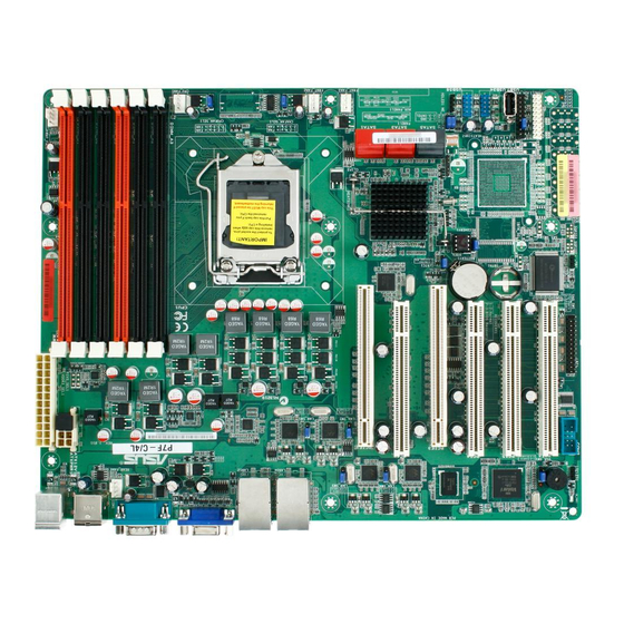
2.2.3 Motherboard layout P7F-C/SAS ASUS P7F-C Series... - Page 24 P7F-C/4L Chapter 2: Hardware information...
-
Page 25: Layout Contents
VGA controller setting (3-pin VGA_SW1)) CPU Fan and Chassis Fan control setting (3-pin CPUFAN_SEL1, CHAFAN_SEL1) LAN controller setting (3-pin LAN_SW1, LAN_SW2) (LAN_SW3, LAN_SW4 P7F-C/4L Model only) RAID configuration utility selection (3-pin RAID_SEL1) (P7F-C/4L Model only) Onboard storage setting (3-pin SAS_SW1) - Page 26 Internal connectors Serial ATA connectors (7-pin SATA1, SATA2, SATA3, SATA4; RED) (7-pin SATA5, SATA6; Black) Hard disk activity LED connector (4-pin HDLED1) SAS connectors (7-pin SAS1, SAS2, SAS3, SAS4; RED) (7-pin SAS5, SAS6, SAS7, SAS8; Blue) (P7F-C/SAS model only) USB connector (10-1 pin USB34, USB56; A-Type USB7) Serial General Purpose Input/Output connector (6-1 pin SGPIO1) Serial General Purpose Input/Output connectors (6-1 pin SGPIO2/3) (P7F-C/SAS model only)
-
Page 27: Central Processing Unit (Cpu)
ASUS will shoulder the cost of repair only if the damage is shipment/transit-related. • Keep the cap after installing the motherboard. ASUS will process Return Merchandise Authorization (RMA) requests only if the motherboard comes with the cap on the LGA1156 socket. - Page 28 Lift the load lever in the direction of the arrow until the load plate is completely lifted. Remove the PnP cap from the CPU socket. Position the CPU over the socket, ensuring that the gold triangle is on the bottom-left corner of the socket, and then fit the socket alignment keys into the CPU notches.
- Page 29 Close the load plate (A), and then push down the load lever (B), ensuring that the front edge of the load plate slides under the retention knob (C). Insert the load lever under the retention tab. ASUS P7F-C Series 2-11...
-
Page 30: Installing The Cpu Heatsink And Fan
2.3.2 Installing the CPU heatsink and fan The Intel LGA1156 processor requires a specially designed heatsink and fan ® assembly to ensure optimum thermal condition and performance. • When you buy a boxed Intel and heatsink assembly. If you buy a CPU separately, ensure that you use only Intel •... -
Page 31: Uninstalling The Cpu Heatsink And Fan
Rotate each fastener counterclockwise. Pull up two fasteners at a time in a diagonal sequence to disengage the heatsink and fan assembly from the motherboard. Carefully remove the heatsink and fan assembly from the motherboard. ASUS P7F-C Series 2-13... -
Page 32: Installing The Cpu Heatsink In Rack
2.3.4 Installing the CPU heatsink in rack The Intel 1156 processors require a specially designed heatsink to ensure ® optimum thermal condition and performance. • Ensure that you use qualified heatsink assembly only. • Ensure that you have applied the thermal interface material to the top of the CPU before installing the heatsink. -
Page 33: System Memory
DO NOT combine RDIMM and UDIMM. • The motherboard supports x8 DRAM Only and x4 & x16 DRAM are not supported ASUS P7F-C Series DIMM Type Speed Registered DDR3 ECC 1333 Registered DDR3 ECC 1066... -
Page 34: Installing A Dimm
2.4.3 Installing a DIMM Unplug the power supply before adding or removing DIMMs or other system components. Failure to do so can cause severe damage to both the motherboard and the components. To install a DIMM: Press the retaining clips outward to unlock a DIMM socket. -
Page 35: Expansion Slots
When using PCI cards on shared slots, ensure that the drivers support “Share IRQ” or that the cards do not need IRQ assignments. Otherwise, conflicts will arise between the two PCI groups, making the system unstable and the card inoperable. ASUS P7F-C Series 2-17... -
Page 36: Interrupt Assignments
2.5.3 Interrupt assignments Standard Interrupt assignments Priority * These IRQs are usually available for ISA or PCI devices. 2-18 Standard function System Timer Keyboard Controller Programmable Interrupt Communications Port (COM2) Communications Port (COM1) Floppy Disk Controller System CMOS/Real Time Clock ACPI Mode when used IRQ Holder for PCI Steering IRQ Holder for PCI Steering... -
Page 37: Pci Express X16 Slots (X8 Link)
The PCI slot supports cards such as a LAN card, USB card, and other cards that comply with PCI 2.3 specifications. PCI Express x16 slot (x8 link) PCI slot PCI Express x16 slot (x8 link) PCI slot PCI slot PCI slot ASUS P7F-C Series 2-19... -
Page 38: Installing I Button
2.5.6 Installing i Button Follow the steps below to install an optional i Button on your motherboard. Locate the I Button slot on the motherboard. Snap the I Button in place. 2.5.7 Connect Thermal sensor cable Follow the steps below to connect the thermal sensor cable to the connector on your motherboard. -
Page 39: Jumpers
Removing the cap will cause system boot failure! If the steps above do not help, remove the onboard battery and move the jumper again to clear the CMOS RTC RAM data. After the CMOS clearance, reinstall the battery. ASUS P7F-C Series 2-21... - Page 40 VGA controller setting (3-pin VGA_SW1) This jumper allows you to enable or disable the onboard VGA controller. Set to pins 1–2 to activate the VGA feature. CPU Fan and Chassis Fan control setting (3-pin CPUFAN_SEL1, CHAFAN_SEL1) These jumpers allow you to switch for fan pin selection. The CPUFAN_SEL1 jumper is for the CPU fan control and the CHAFAN_SEL1 jumper is for the front fans and rear fans control.
- Page 41 LAN controller setting (3-pin LAN_SW1, LAN_SW2) (LAN_SW3, LAN_SW4 P7F-C/4L model only ) These jumpers allow you to enable or disable the onboard Marvell Gigabit LAN controllers. Set to pins 1–2 to activate the Gigabit LAN feature. RAID configuration utility selection (3-pin RAID_SEL1)
- Page 42 Onboard storage setting (3-pin SAS_SW1) (P7F-C/SAS model only) This jumper allows you to enable or disable the onboard LSI1068E SAS controller. Set the jumper to pins 1–2 to enable the SAS function (default). Force BIOS recovery setting (3-pin RECOVERY1) This jumper allows you to quickly update or recover the BIOS settings when it becomes corrupted.
-
Page 43: Connectors
Network (LAN) through a network hub. Refer to the table below for the LAN port LED indications. LAN 3 (RJ-45) port. (P7F-C/4L model only) This port allows Gigabit connection to a Local Area Network (LAN) through a network hub. Refer to the table below for the LAN port LED indications. -
Page 44: Internal Connectors
2.7.2 Internal connectors Serial ATA connectors (7-pin SATA1, SATA2, SATA3, SATA4; RED) (7-pin SATA5, SATA6; Black) Supported by the Intel signal cables for Serial ATA hard disk drives that allows up to 3Gb/s of data transfer rate. If you installed Serial ATA hard disk drives, you can create a RAID 0, RAID 1, RAID 10, or RAID 5 configuration. - Page 45 These connectors are for USB 2.0 ports. Connect the USB module cables to connectors USB34 and USB56, then install the modules to a slot opening at the back of the system chassis. These USB connectors comply with USB 2.0 specification that supports up to 480 Mbps connection speed. ASUS P7F-C Series 2-27...
- Page 46 Serial General Purpose Input/Output connector (6-1 pin SGPIO1) This connector is used for the SGPIO peripherals for the LSI MegaRAID and Intel Matrix RAID SATA LED. Serial General Purpose Input/Output connectors (8-1 pin SGPIO2/3) (P7F-C/SAS model only) These connector is used for the SAS chip SGPIO interface that controls the LED pattern generation, device information and general purpose data.
- Page 47 DO NOT forget to connect the fan cables to the fan connectors. Insufficient air flow inside the system may damage the motherboard components. • These are not jumpers! DO NOT place jumper caps on the fan connectors! • All fans feature the ASUS Fan Speed Control technology. ASUS P7F-C Series 2-29...
- Page 48 ATX power connectors (24-pin EATXPWR1, 8-pin EATX12V1) These connectors are for an ATX power supply plugs. The power supply plugs are designed to fit these connectors in only one orientation. Find the proper orientation and push down firmly until the connectors completely fit. •...
- Page 49 11. Parallel port connector (26-1 pin LPT1) This connector is for a parallel port. Connect the parallel port module cable to this connector, then install the module to a slot opening at the back of the system chassis. ASUS P7F-C Series 2-31...
-
Page 50: System Panel Connector
12. System panel connector (20-pin PANEL1) This connector supports several chassis-mounted functions. System power LED (3-pin PLED) This 3-pin connector is for the system power LED. Connect the chassis power LED cable to this connector. The system power LED lights up when you turn on the system power, and blinks when the system is in sleep mode. -
Page 51: Auxiliary Panel Connector
Connect the Locator LED cables to these 2-pin connector. The LEDs will light up when the Locator button is pressed. Locator Button/Swich (2-pin LOCATORBTN) These leads are for the locator button on the front panel. This button queries the state of the system locator. ASUS P7F-C Series 2-33... - Page 52 2-34 Chapter 2: Hardware information...
-
Page 53: Chapter 3: Powering Up
This chapter describes the power up sequence, and ways of shutting down the system. Powering up... - Page 54 Chapter summary Starting up for the first time ... 3-3 Turning off the computer ... 3-4 ASUS P7F-C Series...
-
Page 55: Starting Up For The First Time
Check the jumper settings and connections or call your retailer for assistance. At power on, hold down the <Del> key to enter the BIOS Setup. Follow the instructions in Chapter 4. ASUS P7F-C Series... -
Page 56: Powering Off The Computer
Powering off the computer 3.2.1 Using the OS shut down function If you are using Windows Click the Start button then click Shut Down. Select Shut Down from the What do you want the computer to do? list box. Select Shutdown Event Tracker. Ensure that the Planned check box is checked. -
Page 57: Chapter 4: Bios Setup
This chapter tells how to change the system settings through the BIOS Setup menus. Detailed descriptions of the BIOS parameters are also provided. BIOS setup... - Page 58 Managing and updating your BIOS ... 4-1 BIOS setup program ... 4-7 Main menu ... 4-10 Advanced menu ... 4-16 Server menu ... 4-29 Power menu ... 4-31 Boot menu ... 4-34 Tools menu ... 4-38 Exit menu ... 4-39 ASUS P7F-C Series...
-
Page 59: Managing And Updating Your Bios
BIOS using the BUPDATER utility. 4.1.1 ASUS EZ Flash 2 utility The ASUS EZ Flash 2 feature allows you to update the BIOS without having to use a DOS-based utility. Before you start using this utility, download the latest BIOS from the ASUS website at www.asus.com. -
Page 60: Bupdater Utility
Updating the BIOS file To update the BIOS file using the BUPDATER utility: Visit the ASUS website at www.asus.com and download the latest BIOS file for the motherboard. Save the BIOS file to a bootable USB flash disk drive. Copy the BUPDATER utility (BUPDATER.exe) from the ASUS support website at support.asus.com to the bootable USB flash disk drive you created... - Page 61 The utility returns to the DOS prompt after the BIOS update process is completed. Reboot the system from the hard disk drive. The BIOS update is finished! Please restart your system. C:\> ASUS P7F-C Series Update ROM BOARD: P7F-C Series...
-
Page 62: Asus Crashfree Bios 3 Utility
4.1.3 ASUS CrashFree BIOS 3 utility The ASUS CrashFree BIOS 3 is an auto recovery tool that allows you to restore the BIOS file when it fails or gets corrupted during the updating process. You can update a corrupted BIOS file using a USB flash drive that contains the updated BIOS file. -
Page 63: Bios Setup Program
The BIOS setup screens shown in this section are for reference purposes only, and may not exactly match what you see on your screen. • Visit the ASUS website (www.asus.com) to download the latest BIOS file for this motherboard. ASUS P7F-C Series... -
Page 64: Bios Menu Screen
4.2.1 BIOS menu screen Menu items Menu bar Main Advanced System Time System Date SATA 1 SATA 2 SATA 3 SATA 4 SATA 5 SATA 6 Storage Configuration System Information v02.61 (C)Copyright 1985-2009, American Megatrends, Inc. Sub-menu items 4.2.2 Menu bar The menu bar on top of the screen has the following main items: Main For changing the basic system configuration... -
Page 65: Menu Items
4.2.9 General help At the top right corner of the menu screen is a brief description of the selected item. ASUS P7F-C Series System Time [11:17:09] System Date [Wed 11/25/2009] SATA1... -
Page 66: Main Menu
Main menu When you enter the BIOS Setup program, the Main menu screen appears, giving you an overview of the basic system information. Refer to section 4.2.1 BIOS menu screen for information on the menu screen items and how to navigate through them. Main Advanced System Time... - Page 67 Configuration options: [Disabled] [Auto] PIO Mode [Auto] Allows you to select the data transfer mode. Configuration options: [Auto] [0] [1] [2] [3] [4] ASUS P7F-C Series BIOS SETUP UTILITY Select the type of device connected to the system.
- Page 68 DMA Mode [Auto] Sets the DMA mode. Configuration options: [Auto] [SWDMA0] [SWDMA1] [SWDMA2] [MWDMA0] [MWDMA1] [MWDMA2] [UDMA0] [UDMA1] [UDMA2] [UDMA3] [UDMA4] [UDMA5] SMART Monitoring [Auto] Sets the Smart Monitoring, Analysis, and Reporting Technology. Configuration options: [Auto] [Disabled] [Enabled] 32Bit Data Transfer [Enabled] Enables or disables 32-bit data transfer.
-
Page 69: Storage Configuration
BIOS. Configuration option: [Disabled] [Enabled] IDE Detect Time Out (Sec) [35] Selects the time out value for detecting ATA/ATAPI devices. Configuration options: [0] [5] [10] [15] [20] [25] [30] [35] ASUS P7F-C Series BIOS SETUP UTILITY [Enhanced] [IDE] [Disabled]... -
Page 70: Ahci Configuration
4.3.5 AHCI Configuration This menu is the section for AHCI configuration. It appears only when you set the item Configure SATA as from the sub-menu of SATA Configuration to [AHCI]. Main AHCI Settings SATA Port1 [Not Detected] SATA Port2 [Not Detected] SATA Port3 [Not Detected] SATA Port4 [Not Detected] SATA Port5 [Not Detected]... -
Page 71: System Information
System Memory Information Speed DDR3 1333 DIMM_A1 20484 MB, 2R, 1333 DIMM_A2 DIMM_A3 DIMM_B1 DIMM_B2 DIMM_B3 ASUS P7F-C Series BIOS SETUP UTILITY X3440 @ ←→ ↑↓ Enter Go to Sub Screen BIOS SETUP UTILITY Select Screen Select Item General Help... -
Page 72: Advanced Menu
Advanced menu The Advanced menu items allow you to change the settings for the CPU and other system devices. Take caution when changing the settings of the Advanced menu items. Incorrect field values can cause the system to malfunction. Main Advanced CPU Configuration Chipset... - Page 73 Configuration options: [Disabled] [Enabled] CPU TM Function [Enabled] This function enables the overheated CPU to throttle the clock speed to cool down. Configuration options: [Disabled] [Enabled] ASUS P7F-C Series BIOS SETUP UTILITY Sets the ratio between [Enabled]...
- Page 74 Execute-Disable Bit Capability [Enabled] Allows you to enable or disable the No-Execution Page Protection Technology. Setting this item to [Disabled] forces the XD feature flag to always return to zero (0). Configuration options: [Disabled] [Enabled] Intel(R) HT Technology [Enabled] Allows you to enable or disable the Intel Hyper-Threading Technology function. When disabled, only one thread per activated core is enabled.
- Page 75 C1 based on the uncore auto-demote information. Configuration options: [Disabled] [Enabled] C3 Auto Demotion [Enabled] When this item is enabled, the CPU will conditionally demote C6/C7 requests to C3 based on the uncore auto-demote information. Configuration options: [Disabled] [Enabled] ASUS P7F-C Series 4-19...
-
Page 76: Chipset
You may allow the system to detect DDR3 memory frequency via SPD or designate a specific frequency. Configuration options: [Auto] [800 MHz] [1066 MHz] [1333 MHz] Refer to the memory AVL on ASUS website at www.asus.com. 4-20 BIOS SETUP UTILITY ←→... - Page 77 DRAM Margin Ranks [Disabled] Configuration options: [Enabled] [Disabled] MRC Serial Debug Message Level [Disabled] Configuration options: [Disabled] [Minimum] [Maximum] [Test] Memory ECC Function [Enabled] Allows you to enable or disable Memory ECC fucntion. Configuration options: [Disabled] [Enabled] ASUS P7F-C Series 4-21...
-
Page 78: Onboard Devices Configuration
Double Rate Refresh [Auto] Allows you to enable or disable Double Rate Refresh. Configuration options: [Auto] [Disabled] Page Poilcy [Closed] Configuration options: [Closed] [Open] Adaptive Page [Disabled] Configuration options: [Disabled] [Enabled] Data Scramble [Disabled] Configuration options: [Disabled] [Enabled] Memory Thermal Throttling [Disabled] Setting this item to [CLTT] to Closed Loop Thermal Throttling and [OLTT] to Open Loop Thermal Throttling. - Page 79 Onboard LAN1/2/3/4 Boot ROM [PXE] Allows you to configure the onboard LAN1/2/3/4 boot mode. Configuration: [Disabled] [PXE] Onboard LAN3/4 Boot ROM are available only for P7F-C/4L model. LSI 1068E Boot ROM [Enabled] Allows you to configure the onboard LSI 1068E boot mode.
-
Page 80: Usb Configuration
4.4.4 USB Configuration Advanced USB Configuration Module Version - 2.24.5-13.4 USB Devices Enabled: 2 Hubs USB Functions Legacy USB Support BIOS EHCI Hand-off v02.61 (C)Copyright 1985-2008, American Megatrends, Inc. USB Functions [Enabled] Allows you to enabled or disable the USB function. Configuration options: [Disabled] [Enabled] Legacy USB Support [Enabled] Allows you to enable or disable support for legacy USB devices. -
Page 81: Pcipnp
Configuration options: [Bus 0 First] [Bus N First] Onboard Option ROM Priority [Normal] Allows you to select the onboard option ROM priority. Configuration options: [Normal] [High] ASUS P7F-C Series BIOS SETUP UTILITY NO: lets the BIOS configure all the devices in the system. -
Page 82: Acpi Configuration
4.4.6 ACPI Configuration Advanced ACPI Settings Advanced ACPI Configuration Chipset ACPI Configuration General WHEA Configuration v02.61 (C)Copyright 1985-2009, American Megatrends, Inc. Advanced ACPI Configuration Advanced Advanced ACPI Configuration ACPI APIC support BIOS-->AML ACPI table Headless mode ACPI APIC Support [Enabled] Allows you to enable or disable the Advanced Configuration and Power Interface (ACPI) support in the Advanced Programmable Interrupt Controller (APIC). - Page 83 Configuration options: [FED00000h] [FED01000h] [FED02000h] [FED03000h] General WHEA Configuration Advanced General WHEA Configuration WHEA Support WHEA Support [Enabled] Allows you to enable or disable the Windows Hardware Error Architecture. Configuration options: [Disabled] [Enabled] ASUS P7F-C Series BIOS SETUP UTILITY [Disabled] Enabled [Disabled] Disabled [Enabled] [FED00000h]...
-
Page 84: Event Log Configuration
4.4.7 Event Log Configuration Main Advanced Event Logging details View Event Log Mark all event as read Clear Event Log View Event Log Press <Enter> to read all the unread event log. Mark all events as read Press <Enter> to mark all the events as read. Clear Event Log Press <Enter>... -
Page 85: Server Menu
(C)Copyright 1985-2009, American Megatrends, Inc. Remote Access [Enabled] Enables or disables the remote access feature. Configuration options: [Disabled] [Enabled] The following items appear only when Remote Access is set to [Enabled]. ASUS P7F-C Series BIOS SETUP UTILITY Power Boot Tools... - Page 86 Serial port number [COM2] Selects the serial port for console redirection. Configuration options: [COM1] [COM2] Base Address. IRQ [2F8h, 3] This item is not user-configurable and changes with the configuration of Serial port number. Serial Port Mode [57600 8,n,1] Sets the Serial port mode. Configuration options: [115200 8,n,1] [57600 8,n,1] [38400 8,n,1] [19200 8,n,1] [09600 8,n,1] Flow Control [Hardware]...
-
Page 87: Power Menu
When set to [Power On], the system will reboot after an AC power loss. When set to [Last State], the system goes into either off or on state, whatever the system state was before the AC power loss. Configuration options: [Power Off] [Power On] [Last State] ASUS P7F-C Series BIOS SETUP UTILITY Power Boot... - Page 88 Power On By RTC Alarm [Disabled] Allows you to enable or disable RTC to generate a wake-up event. Configuration options: [Disabled] [Enabled] The following items appear only when the Resume On RTC Alarm item is set to [Enabled]. RTC Alarm Date [15] To set the alarm date, highlight this item and press the <+>...
-
Page 89: Hardware Monitor
[N/A]. Fan Speed Control [Generic Mode] Allows you to configure the ASUS Smart Fan feature that smartly adjusts the fan speeds for more efficient system operation. Configuration options: [Full Speed Mode] [High Density Mode] [Generic Mode] [Whisper Mode] VCORE1, 3.3V Voltage, 5V Voltage, 12V Voltage, VBAT Voltage,... -
Page 90: Boot Menu
Boot menu The Boot menu items allow you to change the system boot options. Select an item then press <Enter> to display the sub-menu. Main Advanced Boot Settings Boot Device Priority Boot Settings Configuration Security v02.61 (C)Copyright 1985-2009, American Megatrends, Inc. 4.7.1 Boot Device Priority Boot Device Priority... -
Page 91: Boot Settings Configuration
Allows you to enable or disable the full screen logo display feature. Configuration options: [Disabled] [Enabled] Set this item to [Enabled] to use the ASUS MyLogo2™ feature. AddOn ROM Display Mode [Force BIOS] Allows you to set the display mode for Options ROM. -
Page 92: Security
4.7.4 Security The Security menu items allow you to change the system security settings. Select an item then press <Enter> to display the configuration options. Security Settings Supervisor Password : Not Installed User Password Change Supervisor Password Change User Password v02.61 (C)Copyright 1985-2009, American Megatrends, Inc. -
Page 93: Change User Password
When set to [Setup], BIOS checks for user password when accessing the Setup utility. When set to [Always], BIOS checks for user password both when accessing Setup and booting the system. Configuration options: [Setup] [Always] ASUS P7F-C Series BIOS SETUP UTILITY Power... -
Page 94: Tools Menu
4.8.1 ASUS EZ Flash 2 Allows you to run ASUS EZ Flash 2. When you press <Enter>, a confirmation message appears. Use the left/right arrow key to select between [Yes] or [No], then press <Enter> to confirm your choice. Check section 4.1.1 ASUS EZ Flash 2 utility for details. -
Page 95: Exit Menu
Setup menus. When you select this option or if you press <F5>, a confirmation window appears. Select YES to load default values. Select Exit & Save Changes or make other changes before saving the values to the non-volatile RAM. ASUS P7F-C Series BIOS SETUP UTILITY Power... - Page 96 4-40 Chapter 4: BIOS setup...
- Page 97 This chapter provides instructions for setting up, creating, and configuring RAID sets using the available utilities. RAID configuration...
- Page 98 Chapter summary Setting up RAID ... 5-3 Intel Matrix Storage Manager Option ROM Utility ... 5-5 ® LSI Logic MPT Setup Utility (P7F-C/SAS model only) ... 5-15 LSI Software RAID Configuration Utility (P7F-C/4L model only) ... 5-35 ASUS P7F-C Series...
-
Page 99: Setting Up Raid
LSI1068E PCI-E SAS controller (P7F-C/SAS model only) supports SAS disk • drives and RAID0, RAID1, and RAID1E configuration. LSI MegaRAID software RAID Configuration Utility (P7F-C/4L model only) • with RAID 0, RAID 1, and RAID 10 support (for both Linux and Windows OS). -
Page 100: Installing Hard Disk Drives
5.1.2 Installing hard disk drives The motherboard supports Serial ATA for RAID set configuration. For optimal performance, install identical drives of the same model and capacity when creating a disk array. To install the SATA hard disks for RAID configuration: Install the SATA hard disks into the drive bays following the instructions in the system user guide. -
Page 101: Intel ® Matrix Storage Manager Option Rom Utility
The RAID BIOS setup screens shown in this section are for reference only and may not exactly match the items on your screen. ASUS P7F-C Series All Rights Reserved. MAIN MENU 3. Reset Disks to Non-RAID 4. -
Page 102: Creating A Raid Set
5.2.1 Creating a RAID set To create a RAID set From the utility main menu, select 1. Create RAID Volume and press <Enter>. The following screen appears. Intel(R) Matrix Storage Manager option ROM v8.9.0.1023 PCH-D wRAID5 Copyright(C) 2003-09 Intel Corporation. Enter a unique volume name that has no special characters and is [↑↓]Change Enter a name for the RAID set and press <Enter>. -
Page 103: Creating A Recovery Set
Intel(R) Matrix Storage Manager option ROM v8.9.0.1023 PCH-D wRAID5 Copyright(C) 2003-09 Intel Corporation. RAID Level: Strip Size: Enter a unique volume name that has no special characters and is [↑↓]Change [TAB]-Next ASUS P7F-C Series All Rights Reserved. CREATE VOLUME MENU Name: Volume0 RAID0(Stripe) Disks:... - Page 104 Enter a name for the recovery set and press <Enter>. When the RAID Level item is selected, press the up/down arrow key to select Recovery, and then press <Enter>. When the Disks item is selected, press <Enter> to select the hard disk drives you want to include in the recovery set.
-
Page 105: Deleting A Raid Set
Are you sure you want to delete volume “Volume0”? (Y/N): Press <Y> to delete the RAID set and return to the utility main menu, or press <N> to return to the DELETE VOLUME menu. ASUS P7F-C Series All Rights Reserved. DELETE VOLUME MENU... -
Page 106: Resetting Disks To Non-Raid
5.2.4 Resetting disks to Non-RAID Take caution before you reset a RAID volume hard disk drive to non-RAID. Resetting a RAID volume hard disk drive deletes all internal RAID structure on the drive. To reset a RAID set hard disk drive From the utility main menu, select 3. -
Page 107: Recovery Volume Options
Use the up/down arrow key to select a drive, and then press <Space> to select. A small triangle marks the selected drive. Press <Enter> after completing your selection and return to the utility main menu. ASUS P7F-C Series All Rights Reserved. RECOVERY VOLUME OPTIONS... -
Page 108: Exiting The Intel ® Matrix Storage Manager
5.2.6 Exiting the Intel To exit the utility From the utility main menu, select 5. Exit, and then press <Enter>. The following warning message appears. Press <Y> to exit or press <N> to return to the utility main menu. 5.2.7 Rebuilding the RAID This option is only for the RAID 1 set. -
Page 109: Rebuilding The Raid With A New Hard Disk
Select a destination disk with the same size as the original hard disk. Reboot the system and then follow the steps in section Rebuilding the RAID with other non-RAID disk on page 5-32. ASUS P7F-C Series All Rights Reserved. MAIN MENU 3. -
Page 110: Setting The Boot Array In The Bios Setup Utility
5.2.8 Setting the Boot array in the BIOS Setup Utility You can set the boot priority sequence in the BIOS for your RAID arrays when creating multi-RAID using the Intel To set the boot array in the BIOS: Set at least one of the arrays bootable to boot from the hard disk. Reboot the system and press <Del>... -
Page 111: Lsi Logic Mpt Setup Utility (P7F-C/Sas Model Only)
Turn on the system after installing all SAS hard disk drives. During POST, press <Ctrl+C> to enter the SAS configuration utility. LSI Logic Corp. MPT SAS BIOS MPTBIOS-6.16.00.00 (2007.05.07) Copyright 2000-2007 LSI Logic Corp. Adapter(s) disabled by user Press Ctrl-C to start LSI Logic Configuration Utility... ASUS P7F-C Series 5-15... - Page 112 The following screen appears. Select a channel and press <Enter> to enter the setup. LSI Logic Config Utility Adapter List Global Properties Adapter SAS1068E Esc = Exit Menu F1/Shift+1 = Help Alt+N = Global Properties -/+ = Alter Boot Order The numbers of the channel depend on the controller.
- Page 113 The disk has been selected as the Hot Spare for the RAID array. • The disk is already part of another array. ASUS P7F-C Series v6.16.00.00 (2007.05.07) Create Integrated Mirror Array of 2 disks plus up to 2 optional hot spares.
- Page 114 A confirmation screen appears. Press <M> to keep existing data on the first disk. If you choose this option, data on the first disk will be mirrored on the second disk that you will add to the volume later. Make sure the data you want to mirror is on the first disk. Press <D>...
-
Page 115: Integrated Mirroring Enhanced
Select New Array Type -- SAS1068E Create IM Volume Create IME Volume Create IS Volume Esc = Exit Menu F1/Shift+1 = Help Enter = Choose array type to create ASUS P7F-C Series v6.16.00.00 (2007.05.07) SAS1068E 04:00:00 1.22.01.00-IR 500E0101:23456712 2B.00 Enabled (Enabled BIOS &... - Page 116 The Create New Array screen shows the disks you can add to make up the IME volume. Integrated Mirroring Enhanced (IME) supports three to ten disks, or seven mirrored disks plus two hot spare disks. Use the arrow key to select a disk, then move the cursor to the RAID Disk column.
- Page 117 Save changes then exit this menu Discard changes then exit this menu Exit the Configuration Utility and Reboot The utility creates the array. LSI Logic Config Utility Processing...may take up 1 minute Creating RAID array ASUS P7F-C Series v6.16.00.00 (2007.05.07) 5-21...
-
Page 118: Integrated Striping (Is) Volume
5.3.3 Integrated Striping (IS) volume Overview The Integrated Striping (IS) feature provides RAID 0 functionality, supporting volumes with two to eight disks. You may combine an IS volume with an IM or IME volume. Creating Integrated Striping volumes DO NOT combine Serial ATA and SAS disk drives in one volume. To create an IS volume: Turn on the system after installing all SAS hard disk drives. - Page 119 The disk has been selected as the Hot Spare for the RAID array. • The disk is already part of another array. ASUS P7F-C Series v6.16.00.00 (2007.05.07) Create Integrated Mirror Array of 2 disks plus up to 2 optional hot spares.
- Page 120 Repeat step 5 to add the other disks to the volume. When done, press <C> to create the array, then select Save changes then exit this menu. Create and save new array? Cancel Exit Save changes then exit this menu Discard changes then exit this menu Exit the Configuration Utility and Reboot The utility creates the array.
-
Page 121: Managing Arrays
Select New Array Type -- SAS1068E View Existing Array Create IM Volume Create IME Volume Create IS Volume Esc = Exit Menu F1/Shift+1 = Help Enter = Choose array type to create ASUS P7F-C Series v6.16.00.00 (2007.05.07) SAS1068E 04:00:00 1.22.01.00-IR 500E0101:23456712 2B.00 Enabled (Enabled BIOS &... - Page 122 The View Existing Array screen appears. Here you can view properties of the RAID array(s) created. If you have configured a hot spare, it will also be listed. if you created more than one array, you may view the next array by pressing <Alt+N>.
-
Page 123: Managing Hot Spares
Type Scan Order Size(MB) Status Manage Hot Spare Synnchronize Array Activate Array Delete Array Esc = Exit Menu Enter = Select Item ASUS P7F-C Series v6.16.00.00 (2007.05.07) 1 of 1 LSILOGICLogical Volume 3000 51498 Optimal RAID Drive Disk Status 0003... - Page 124 Use the arrow key to select the disk you would like to configure as hot spare, then move the cursor to the Hot Spr column. Press <+>, <->, or <Space>. The Drive Status column field now shows Hot Spare. Press <C> to commit the changes. LSI Logic Config Utility Manage Hot Spare -- SAS1068E Identifier...
-
Page 125: Activating An Array
Manage Hot Spare Synnchronize Array Activate Array Delete Array Esc = Exit Menu Enter = Select Item Press <Y> to delete, or <N> to cancel. ASUS P7F-C Series v6.16.00.00 (2007.05.07) LSILOGICLogical Volume 3000 51498 Optimal F1/Shift+1 = Help v6.16.00.00 (2007.05.07) -
Page 126: Viewing Sas Topology
5.3.5 Viewing SAS topology From the Adapter Properties screen, select SAS Topology. LSI Logic Config Utility Adapter Properties -- SAS1068E Adapter PCI Slot PCI Address(Bus/Dev/Func) MPT Firmware Revision SAS Address NVDATA Version Status Boot Order Boot Support RAID Properties SAS Topology Advanced Adapter Properties Esc = Exit Menu Enter = Select Item -/+ = Change Item... -
Page 127: Global Properties
Pause When Boot Alert Displayed Boot Information Display Mode Support Interrupt Restore Defaults Esc = Exit Menu F1/Shift+1 = Help Alt+N = Adapter List -/+ = Change Item ASUS P7F-C Series v6.16.00.00 (2007.05.07) FW Revision Status Boot Order 1.22.01.00-IR Enabled Ins/Del = Alter Boot List v6.16.00.00 (2007.05.07) - Page 128 Boot Information Display Mode Sets the disk information display mode. Configuration options: [Display adapters & installed devices] [Display adapters only] [Display adapters and all devices] [Display minimal information] LSI Logic Config Utility Adapter List Global Properties Pause When Boot Alert Displayed Boot Information Display Mode Support Interrupt Restore Defaults...
-
Page 129: Restore Defaults
Pause When Boot Alert Displayed Boot Information Display Mode Support Interrupt Restore Defaults Esc = Exit Menu F1/Shift+1 = Help Alt+N = Adapter List -/+ = Change Item ASUS P7F-C Series v6.16.00.00 (2007.05.07) [No] [Display adapters & installed devices] [Hook interrupt, the Default] 5-33... -
Page 130: Lsi Software Raid Configuration Utility (P7F-C/4L Model Only)
LSI Software RAID Configuration Utility (P7F-C/4L model only) The LSI MegaRAID software RAID configuration utility allows you to create RAID 0, RAID 1, or RAID 10 set(s) from SATA hard disk drives connected to the SATA connectors supported by the motherboard southbridge chip. -
Page 131: Creating A Raid Set
Clear Configuration Objects Select Boot Drive Rebuild Check Consistency Defines Physical Arrays. An Array Will Automatically Become A VD Use Cursor Keys to Navigate Between Items And Press Enter To Select An Option ASUS P7F-C Series BIOS Version A.09.04300936R 5-35... - Page 132 The ARRAY SELECTION MENU displays the available drives connected to the SATA ports. Use the up/down arrow key to select the drives you want to include in the RAID set, and then press <Space>. When selected, the drive indicator changes from READY to ONLIN A[X]-[Y], where X is the array number, and Y is the drive number.
- Page 133 Virtual Drive 0 RAID = 1 Size = 77247MB DWC = Off = On Accept SPAN = NO Cursor Keys, SPACE-(De)Select F2-ChIdInfo F3-SlotInfo F10-Configure Esc-Quit ASUS P7F-C Series BIOS Version A.09.04300936R Virtual Drive(s) Configured Size #Stripes StripSz 77247MB 64 KB...
- Page 134 When creating a RAID 1 or a RAID 10 set, select DWC from the Virtual Drive menu, and then press <Enter>. When creating a RAID 0 set, proceed to step 10. Select On to enable the Disk Write Cache setting, and then press <Enter>. LSI Software RAID Configuration Utility Ver A.62 Apr 29, 2009 Management Menu Configure...
-
Page 135: Using New Configuration
Select Boot Drive Objects Rebuild Check Consistency Clear Existing Configuration And Start A New Configuration Use Cursor Keys to Navigate Between Items And Press Enter To Select An Option ASUS P7F-C Series BIOS Version A.09.04300936R Save Configuration? Virtual Drive(s) Configured Size... - Page 136 Follow step 2 to 7 of the previous section: Using Easy Configuration. Select Size from the Virtual Drive menu, and then press <Enter>. Key-in the desired virtual drive size, and then press <Enter>. LSI Software RAID Configuration Utility Ver A.62 Apr 29, 2009 Management Menu Configure Initialize...
-
Page 137: Adding Or Viewing A Raid Configuration
The information of the selected hard disk drive displays at the bottom of the screen. Follow step 3 to 12 of section 5.2.1 Creating a RAID set: Using Easy Configuration to add a new RAID set. ASUS P7F-C Series BIOS Version A.09.04300936R BIOS Version A.09.04300936R... -
Page 138: Initializing The Virtual Drives
5.4.3 Initializing the virtual drives After creating the RAID set(s), you must initialize the virtual drives. You may initialize the virtual drives of a RAID set(s) using the Initialize or Objects command on the Management Menu. Using the Initialize command To initialize the virtual drive using the Initialize command From the Management Menu, select Initialize, and then press <Enter>. - Page 139 LSI Software RAID Configuration Utility Ver A.62 Apr 29, 2009 Management Menu Configure Initialize Objects VD 0 Initialization Complete. Press Esc.. Rebuild Check Consistency Virtual Drives Virtual Drive 0 SPACE-(De)Select, F10-Initialize ASUS P7F-C Series BIOS Version A.09.04300936R Virtual Drive(s) Configured RAID Size #Stripes 154494MB Initialize? BIOS Version A.09.04300936R...
- Page 140 Using the Objects command To initialize the virtual drives using the Objects command From the Management Menu, select Objects > Virtual Drive, and then press <Enter>. LSI Software RAID Configuration Utility Ver A.62 Apr 29, 2009 Management Menu Adapter Configure Virtual Drive Initialize Physical Drive...
- Page 141 Use Cursor Keys To Navigate Between Items And Press Enter To Select An Option A progress bar appears on screen. If desired, press <Esc> to abort initialization. When initialization is completed, press <Esc>. ASUS P7F-C Series BIOS Version A.09.04300936R Vitual Drive(1)
-
Page 142: Rebuilding Failed Drives
5.4.4 Rebuilding failed drives You can manually rebuild failed hard disk drives using the Rebuild command in the Management Menu. To rebuild a failed hard disk drive From the Management Menu, select Rebuild, and then press <Enter>. LSI Software RAID Configuration Utility Ver A.62 Apr 29, 2009 Management Menu Configure Initialize... - Page 143 Rebuilding Of Drive Will Take A Few Minutes. Start Rebuilding Drive (Y/N)? Port # 1 DISK SPACE-(De)Select,F10-Start Rebuild,F2-Drive Information,F3-View Virtual Drives When rebuild is complete, press any key to continue. ASUS P7F-C Series BIOS Version A.09.04300936R PORT # ONLIN A00-00...
-
Page 144: Checking The Drives For Data Consistency
5.4.5 Checking the drives for data consistency You can check and verify the accuracy of data redundancy in the selected virtual drive. The utility can automatically detect and/or detect and correct any differences in data redundancy depending on the selected option in the Objects > Adapter menu. - Page 145 Continue - Continues the consistency check. • Abort - Aborts the consistency check. When you restart checking, it continues from zero percent. When checking is complete, press any key to continue. ASUS P7F-C Series BIOS Version A.09.04300936R Virtual Drive(s) Configured RAID Size...
- Page 146 Using the Objects command To check data consistency using the Objects command From the Management Menu, select Objects, and then select Virtual Drive from the sub-menu. Use the arrow keys to select the virtual drive you want to check, and then press <Enter>.
-
Page 147: Deleting A Raid Configuration
Rebuild Check Consistency Use Cursor Keys To Navigate Between Items And Press Enter To Select An Option The utility clears all the current array(s). Press any key to continue. ASUS P7F-C Series BIOS Version A.09.04300936R Clear Existing Configuration BIOS Version A.09.04300936R... -
Page 148: Selecting The Boot Drive From A Raid Set
5.4.7 Selecting the boot drive from a RAID set You must have created a new RAID configuration before you can select the boot drive from a RAID set. See section 5.2.1 Creating a RAID set: Using New Configuration for details. To select the boot drive from a RAID set From the Management Menu, select Configure >... -
Page 149: Enabling Writecache
Check Consistency Disk Write Cache - Off(Write Through) or On(Write Back) Use Cursor Keys To Navigate Between Items And Press Enter To Select An Option When finished, press any key to continue. ASUS P7F-C Series BIOS Version A.09.04300936R Adapter 0... - Page 150 5-54 Chapter 5: RAID configuration...
-
Page 151: Chapter 6: Driver Installation
This chapter provides instructions for installing the necessary drivers for different system components. Driver installation... - Page 152 Chapter summary RAID driver installation ... 6-3 Intel chipset device software installation ... 6-19 LAN driver installation ... 6-21 VGA driver installation... 6-23 Management application and utilities installation ... 6-25 ASUS P7F-C Series...
-
Page 153: Raid Driver Installation
Use the arrow keys to select the type of RAID driver disk you want to create and press <Enter> to enter the sub-menu. PCH INTEL RAID Driver PCH INTEL RAID Driver Windows 32 bit(also support AHCI) Windows 64 bit(also support AHCI) Back Exit ASUS P7F-C Series ®... - Page 154 PCH LSI RAID Driver PCH LSI RAID Driver Windows XP 32 bit Windows XP 64 bit Windows Server 2003 32 bit Windows Server 2003 64 bit Windows Vista 32 bit Windows Vista 64 bit Windows Server 2008 32 bit Windows Server 2008 64 bit RHEL AS4 UP5 32/64 bit RHEL AS4 UP6 32/64 bit RHEL AS4 UP7 32/64 bit...
- Page 155 Type dd if=XXX.img of=/dev/fd0 to decompress the file into the floppy disk from the following path in the support DVD: For LSI MegaRAID Driver \Drivers\PCH LSI RAID\Driver\makedisk\Linux Eject the floppy disk. ASUS P7F-C Series ® environment Enterprise Linux server environment ®...
-
Page 156: Installing The Raid Controller Driver
6.1.2 Installing the RAID controller driver Windows Server OS ® During Windows To install the RAID controller driver when installing Windows Boot the computer using the Windows ® Windows Server OS Setup starts. Windows Setup Press F6 if you need to install a third party SCSI or RAID driver... Press <F6>... - Page 157 Next. 10. The wizard searches the RAID controller drivers. When found, click Next to install the drivers. 11. Click Finish after the driver installation is done. ASUS P7F-C Series into Drive A: Press ENTER when ready. F3=Exit Server OS ®...
- Page 158 To verify the RAID controller driver installation: Right-click the My Computer icon on the Windows Properties from the menu. Click the Hardware tab, and then click the Device Manager button. Click the “+” sign before the item SCSI and RAID controllers, and then the Intel(R) ICH8R/ICH9R/ICH10R/DO/PCH SATA RAID Controller item should appear.
- Page 159 Insert your driver disk into /dev/sda and press “OK” to continue. Select No and press <Enter> to continue. More Driver Disks? Do you wish to load any more driver disks? ASUS P7F-C Series Red Hat OS installation CD. ® Cancel Enterprise OS:...
- Page 160 Select your desired language and press <Enter> to continue. Choose a Language What language would you like to use during the installation process? Catalan Chinese(Simplified) Chinese(Traditional) Croatian Czech Danish Dutch English Select your keyboard type and press <Enter> to continue. What type of keyboard do you have? ua-utf ua-utf-ws...
- Page 161 Unable to find any devices of the type needed for this installation type. Would you like to manually select your driver or use a driver disk? Select driver ASUS P7F-C Series Back No driver found Use a driver disk Back...
- Page 162 11. Scroll down to locate the driver and press <Enter> to continue. Please select the driver below which you wish to load. If it does not appear and you have a driver disk, press F2. LSI Logic Fusion MPT SPI Driver (mptspi) LSI MegaRAID Controllers (megaraid_mbox) LSI MegaRAID Controllers (megaraid_sas) LSI megasr Driver ver 13.10.0708.2009 (megasr)
- Page 163 LSI megasr Driver ver 13.10.0708.2009 (megasr) USB Mass Storage driver for Linux (usb-storage) Done The displayed devices may vary with models and systems. 14. Follow the onscreen instructions to finish installing the RedHat operating system. ASUS P7F-C Series Devices Add Device 6-13...
- Page 164 Red Hat Enterprise Linux OS 5.0 ® To install the RAID controller driver when installing Red Hat Boot the system from the Red Hat At the boot:, type linux dd noprobe=ata[n]. The number of ata varies with the hard disk drive number you have when building a RAID set. For example, if you want to build a RAID set with 6 hard disk drives, type command line: linux dd noprobe=ata1 noprobe=ata2 noprobe=ata3 noprobe=ata4 noprobe=ata5 noprobe=ata6.
- Page 165 Follow the onscreen instructions to finish the OS installation. If you install RHEL AS5, when the installation is completed, DO NOT click Reboot. Press <Ctrl> + <Alt> + <F2> to switch to the command-line interface from graphic user interface. ASUS P7F-C Series Back 6-15...
- Page 166 10. Type the following commands when using a USB floppy. cat /proc/partitions Write down the Major and Minor number before sdb for later use. mknod /dev/sdb b [major number] [minor number] mkdir /mnt/driver mount /dev/sdb /mnt/driver cd /mnt/driver sh replace_ahci.sh reboot 6-16 Chapter 6: Driver installation...
- Page 167 Press <F5>, then select Yes from the menu. Press <Enter>. Boot from Hard Disk Installation Installation--ACPI Disabled Installation--Local APIC Disabled Installation--Safe Settings Rescue System Memory Test Boot Options | Help Language ASUS P7F-C Series 1280 x 1024 Driver File 1280 x 1024 Driver 6-17...
- Page 168 Insert the RAID driver disk to the floppy disk drive. Make sure that Installation from the Boot Options menu is selected, then press <Enter>. Boot Options | Help Language If you install SLES 10, type brokenmodules=ahci after Boot Options and press Enter to continue.
-
Page 169: Intel ® Chipset Device Installation
DVD automatically displays the Drivers menu if Autorun is enabled in your computer. Click the item Intel Chipset Device Software from the menu. The Intel(R) Chipset Device Software window appears. Click Next to start installation. ASUS P7F-C Series ® chipset software on a Windows Server ® chipset device software:... - Page 170 Select Yes to accept the terms of the License Agreement and continue the process. Read the Readme File Information and press Next to continue the installation. After completing the installation, click Finish to complete the setup process. 6-20 Chapter 6: Driver installation...
-
Page 171: Lan Driver Installation
If Autorun is NOT enabled in your computer, browse the contents of the support DVD to locate the file ASSETUP.EXE from the BIN folder. Double- click the ASSETUP.EXE to run the DVD. Click the Marvell Yukon Ethernet Driver to begin installation. ASUS P7F-C Series ® Yukon Ethernet 6-21... - Page 172 Click I accept the terms of the License Agreement and click Install to continue. Marvell MiniPort Driver Setup window appears, showing the installing process. Click Finish to close the wizard. 6-22 Chapter 6: Driver installation...
-
Page 173: Vga Driver Installation
Insert the motherboard/system support CD to the optical drive. The support CD automatically displays the Drivers menu if Autorun is enabled in your computer. The Drivers menu if Autorun is enabled in your computer. The XGI VGA Package window appears, preparing the setup. ASUS P7F-C Series Server ® 6-23... - Page 174 Click Next to start the installation. The system will update the VGA driver automatically. When the installation completes, click Finish to restart your computer before using the program. 6-24 Chapter 6: Driver installation...
-
Page 175: Management Applications And Utilities Installation
The contents of the support DVD are subject to change at any time without notice. Visit the ASUS website (www.asus.com) for updates. 6.5.1 Running the support DVD Place the support DVD to the optical drive. -
Page 176: Utilities Menu
Intel Matrix Storage and LSI MegaRAID driver disks. 6.5.5 Contact information Click the Contact tab to display the ASUS contact information. You can also find this information on the inside front cover of this user guide. 6-26 Chapter 6: Driver installation... -
Page 177: Appendix: Reference Information
This appendix includes additional information that you may refer to when configuring the motherboard. Reference information... - Page 178 Appendix summary P7F-C/SAS block diagram ...A-3 P7F-C/4L block diagram ...A-4 ASUS P7F-C Series...
-
Page 179: P7F-C/Sas Series Block Diagram
P7F-C/SAS Series block diagram ASUS P7F-C Series... -
Page 180: P7F-C/4L Series Block Diagram
P7F-C/4L Series block diagram Appendix A: Reference information...