
Related Manuals for Echo Bear Cat SC5540B


Summary of Contents for Echo Bear Cat SC5540B
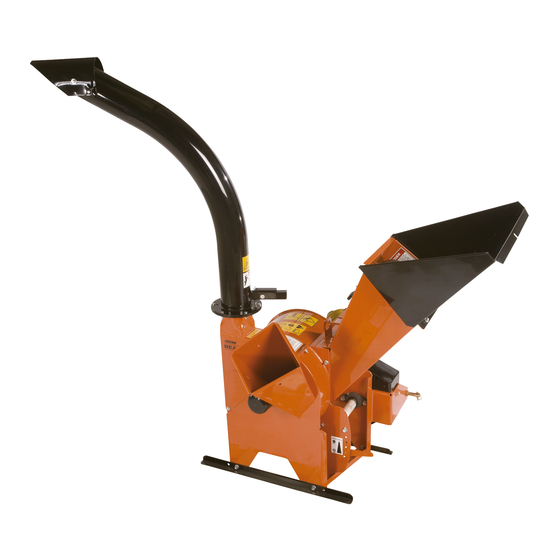
- Page 1 5 INCH CHIPPER/SHREDDER/ BLOWER SC5540B – 540 PTO PN: 13989-00 Rev. 010113 bearcatproducts.com Companion to 13990-00 Range: D00001 - Current...
- Page 2 Please read and understand this manual before operating your machine. If you have any questions or comments about this manual, please call us toll-free at 888.625.4520. If you have any questions or problems with your machine, please call or write your local authorized ECHO Bear Cat dealer.
- Page 3 Repair or attempted repair by anyone other than an authorized ECHO Bear Cat dealer as well as subsequent failure or damage that may occur as a result of that work will not be paid under this warranty.
-
Page 4: Table Of Contents
TABLE OF CONTENTS SAFETY ................................... 1 1.1 SAFETY ALERT SYMBOL ..............................1 1.2 BEFORE OPERATING ................................1 1.3 OPERATION SAFETY ................................2 1.4 PTO SAFETY ..................................3 1.5 MAINTENANCE/STORAGE SAFETY ..........................3 1.6 SAFETY DECALS ................................. 4 1.7 SAFETY DECAL LOCATIONS ............................. 5 ASSEMBLY................................ -
Page 5: Safety
SAFETY Section 1.1 SAFETY ALERT SYMBOL 1.2 BEFORE OPERATING 1. Read and understand this owner’s manual. Be completely familiar with the controls and the proper The Owner/Operator’s manual uses this symbol to alert use of this equipment. you of potential hazards. Whenever you see this symbol, 2. -
Page 6: Operation Safety
SAFETY 11. Always use an approved fuel container. Do not 5. Check cutting chamber to verify it is empty before remove gas cap or add fuel when engine is running. starting the machine. Add fuel to a cool engine only. 6. -
Page 7: Pto Safety
SAFETY 1.4 PTO SAFETY 1.5 MAINTENANCE/STORAGE SAFETY 1. Read and follow instructions on PTO safety decals. 1. Before inspecting, servicing, storing, or changing an accessory, shut off the machine and make sure 2. Stay alert and pay attention when PTO is operating. all moving parts have come to a complete stop. -
Page 8: Safety Decals
SAFETY 1.6 SAFETY DECALS See Section 1.7 for decal locations. Familiarize yourself with all of the safety and operating decals on the machine and the associated hazards. See the engine owner’s manual or contact the engine manufacturer for engine safety instructions and decals. -
Page 9: Safety Decal Locations
SAFETY 1.7 SAFETY DECAL LOCATIONS The numbers below correspond to the decals in Section 1.6. Make certain that all safety and operating decals on this machine are kept clean and in good condition. Decals that need replacement must be applied to their original locations. 6 ** 7 ** *Decal located under shield... -
Page 10: Assembly
ASSEMBLY Section WARNING WARNING If any bolts or nuts are dropped in the machine, be Before inspecting or servicing any part of this machine, sure to remove them before starting the machine. shut off power source, disengage the hydraulics, Remove items from the shredder area by removing the remove ignition key and make sure all moving parts discharge screen. -
Page 11: Attach Discharge Tube
ASSEMBLY NOTE Keep nuts as tight as possible while allowing the discharge tube to freely turn. Figure 2.3, Shredder Chute Tray Attachment to Chute Hinge 2.3 ATTACH DISCHARGE TUBE 1. Attach one clamping ring (1) and one spacer ring (2) to discharge tube base (3) using three 3/8 x 1-1/4"... -
Page 12: Connect The Pto Driveline
ASSEMBLY 2.4 CONNECT THE PTO DRIVELINE The driveline supplied with this machine may need to be IMPORTANT cut to a shorter length for proper operation with the tractor being used. To determine if driveline will need to be cut, ● The tractor must have a standard 540 RPM PTO follow steps below or consult attached driveline manual. -
Page 13: Connect Control Box Wires To Tractor
ASSEMBLY 2.5 CONNECT CONTROL BOX WIRES TO TRACTOR There are two electrical wires (red and white) that come wrapped around the three-point PTO connector. ● Connect the red wire to a 12-volt power source, such as the alternator or the battery. ●... -
Page 14: Features & Controls
FEATURES & CONTROLS Section Understanding how your machine works will help you achieve the best results when using your chipper/shredder/ blower. The following descriptions define the features and controls of your machine. 5. PTO SHAFT Connects the tractor PTO to the chipper/shredder drive shaft. -
Page 15: Operation
OPERATION Section As with any other piece of outdoor equipment, getting the NOTE feel for how your machine operates and getting to know the best techniques for particular jobs are important to This chipper is designed to be used with tractor PTOs overall good performance. -
Page 16: Chipper Operation Guidelines
OPERATION 4.4 CHIPPER OPERATION GUIDELINES 9. ALWAYS feed brush from the side of the chipper WARNING chute, rather than from the front. Step aside to avoid being hit by the brush moving into the chipper. Read and follow all safety instructions in this manual. 10. -
Page 17: Service & Maintenance
SERVICE & MAINTENANCE Section 5.1 MAINTENANCE SCHEDULE The items listed in this service and maintenance schedule WARNING are to be checked, and if necessary, corrective action taken. This schedule is designed for units operating under To prevent personal injury or property damage: shut normal conditions. -
Page 18: Rotor Lock
SERVICE & MAINTENANCE WARNING BEFORE INSPECTING OR SERVICING ANY PART OF THIS MACHINE, SHUT OFF POWER SOURCE, AND MAKE SURE ALL MOVING PARTS HAVE COME TO A COMPLETE STOP. ● The base of the cutting edge is worn or has been 5.2 ROTOR LOCK re-sharpened so that it no longer extends past the chipping slot (see below). -
Page 19: Installing The Blades
SERVICE & MAINTENANCE WARNING BEFORE INSPECTING OR SERVICING ANY PART OF THIS MACHINE, SHUT OFF POWER SOURCE, AND MAKE SURE ALL MOVING PARTS HAVE COME TO A COMPLETE STOP. 5.7 SHREDDER KNIVES MAINTENANCE Do not attempt to sharpen shredder knives. Inspect the knives often for signs of damage. -
Page 20: Setting Blade Clearance
SERVICE & MAINTENANCE WARNING BEFORE INSPECTING OR SERVICING ANY PART OF THIS MACHINE, SHUT OFF POWER SOURCE, AND MAKE SURE ALL MOVING PARTS HAVE COME TO A COMPLETE STOP. 8. Once clearance has been set, the lock collars must 5.9 SETTING BLADE CLEARANCE be replaced and retightened. -
Page 21: Drive Belts
SERVICE & MAINTENANCE WARNING BEFORE INSPECTING OR SERVICING ANY PART OF THIS MACHINE, SHUT OFF POWER SOURCE, AND MAKE SURE ALL MOVING PARTS HAVE COME TO A COMPLETE STOP. 2. Open the access cover, exposing the chipper 5.11 DRIVE BELTS shredder compartment. -
Page 22: Lubrication
SERVICE & MAINTENANCE WARNING BEFORE INSPECTING OR SERVICING ANY PART OF THIS MACHINE, SHUT OFF POWER SOURCE, AND MAKE SURE ALL MOVING PARTS HAVE COME TO A COMPLETE STOP. 5.14 LUBRICATION WARNING Polyurea lithium-based greases compatible. Mixing the two grease types may lead to premature failure. -
Page 23: Troubleshooting
Before performing any of the corrections in this troubleshooting chart, refer to the appropriate information contained in this manual for the correct safety precautions and operating or maintenance procedures. Contact your dealer or ECHO Bear Cat for service problems with the machine. - Page 24 TROUBLESHOOTING PROBLEM POSSIBLE CAUSES REMEDY Dull chipper blades Flip, sharpen, or replace Check drive belts, bearings, and pulleys for Drive system vibration bad or worn areas. Check for dull chipper blades. Excessive vibration while running Inspect rotor for damaged or missing Rotor out of balance chipper blades, replace if needed Set blade/anvil clearance to recommended...
-
Page 25: Specifications
SPECIFICATIONS Section DESCRIPTION ENGLISH METRIC Machine Dimensions (L×W×H) 49" × 48" × 78" 125 cm × 122 cm × 198 cm Weight 720 lbs. 326 kg Maximum Chipper Capacity 5" diameter 12.7 cm diameter Chipper Blades 4 reversible (3.125" × 2" × 0.25") 4 reversible (7.9 cm ×... -
Page 26: Bolt Torque
SPECIFICATIONS 7.1 BOLT TORQUE The tables below are for reference purposes only and their use by anyone is entirely voluntary, unless otherwise noted. Reliance on their content for any purpose is at the sole risk of that person and any loss or damage resulting from the use of this information is the responsibility of that person. -
Page 27: Options
OPTIONS Section PART NUMBER DESCRIPTION 70972 KIT, SHREDDER KNIVES 71930-00 KIT, 6" LOW PROFILE DISCHARGE 72493 KIT, CHIPPER BLADE Low Profile Discharge Chute, 71930-00 Shredder Knife Kit, 70972 Chipper Blade Kit, 72493 5 INCH CHIPPER/SHREDDER/BLOWER... - Page 28 ECHO Bear Cat ® bearcatproducts.com 237 NW 12th Street, West Fargo, ND 58078-0849 Phone: 701.282.5520 • Toll Free: 888.625.4520 • Fax: 701.282.9522 E-mail: service@bearcatproducts.com • sales@bearcatproducts.com...