Table of Contents
Advertisement
Quick Links
LASER CLEAN HEATING SYSTEM/VENTED HEATER
INSTALLATION AND OPERATION INSTRUCTIONS
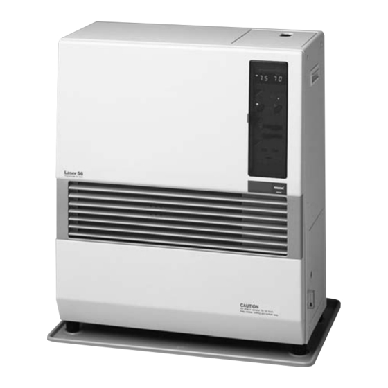
LASER CLEAN VENTED
Laser 56
MODEL
(Type J)
IMPORTANT
READ AND UNDERSTAND INSTRUCTIONS BEFORE INSTALLING OR USING HEATER.
RETAIN INSTRUCTIONS FOR FUTURE REFERENCE. CHECK LOCAL CODES FOR PERMITTED USE.
················································ 2
·············································· 3
···················································· 5
··········································· 9
·················································· 9
Operation
································ 4
················· 6
···································· 12
···································· 12
CONTENTS
························································ 30
············································ 14
········································ 16
······················ 17
························· 17
········································ 19
·························· 22
············· 23
···················· 29
Advertisement
Table of Contents

Related Manuals for Toyotomi Toyostove Laser 56


Summary of Contents for Toyotomi Toyostove Laser 56
-
Page 1: Table Of Contents
LASER CLEAN HEATING SYSTEM/VENTED HEATER INSTALLATION AND OPERATION INSTRUCTIONS LASER CLEAN VENTED Laser 56 MODEL (Type J) IMPORTANT READ AND UNDERSTAND INSTRUCTIONS BEFORE INSTALLING OR USING HEATER. RETAIN INSTRUCTIONS FOR FUTURE REFERENCE. CHECK LOCAL CODES FOR PERMITTED USE. CONTENTS SECTION A: SECTION G: ················································... -
Page 2: Section A
SECTION A: SPECIFICATIONS Model: Laser 56 Heater Efficiency: 93% (1) Heat Rating: High - 22,000 BTU/h (6,453 Watts) Med - 15,000 BTU/h (4,400 Watts) Low - 8,000 BTU/h (2,347 Watts) Fuel Consumption: High - 0.165 gal/h (0.625 L/h) Med - 0.113 gal/h (0.428 L/h) Low - 0.060 gal/h (0.227 L/h) Fuel System: Gravity Fed from Reservoir / Tank (2) -
Page 3: Safety Features
SAFETY FEATURES Your Laser 56 is equipped with the following safety features. Please familiarize yourself with these features. When your heater is extinguished due to a safety mechanism, be sure to identify and correct the problem. Flame Sensor Heater will automatically stop all operations if ignition fails or if flame fails during combustion, in order to prevent fuel overflow. -
Page 4: Section B
SECTION B: SAFETY TIPS FOR OPERATION CAUTION: Heater and vent pipe system must be properly installed before operation. Please follow instructions under “Installation”, Section I. Never use any fuel other than clear or red colored kerosene (ASTM D3699 RIGHT WRONG 1-K Kerosene or ASTM D396 No.1 S500 Low Sulfur No.1 Fuel Oil). -
Page 5: Section C
SECTION C: FUEL GUIDE The Toyostove Laser 56 is designed for use with ASTM D3699 1-K kerosene or ASTM D396 No.1 S500 Low Sulfur No.1 Fuel Oil. Use of low-quality kerosene will cause burner performance to drop, leading to abnormal combustion and reduced heater life. -
Page 6: Section D
SECTION D: OPERATING CONTROLS AND PART NAMES Before using heater, familiarize yourself with the following operating controls and part names. Programmable Set Back ROOM 6. Digital Indicator TEMP 7. Burning mode lamp 9. Auto lamp 8. ON/OFF lamp 2. Auto switch 1. - Page 7 ON/OFF switch: Main switch which turns heater on and off. When switched on, heater begins operation and combustion starts after preheat period. Auto switch: The switch turns automatic operation modes on and off which have been programmed into timer. Temperature selectors: “NORMAL”...
- Page 8 17 16 RE. # PART # DESCRIPTION RE. # PART # DESCRIPTION RE. # PART # DESCRIPTION 20478346 Front panel assembly 20478747 Blower motor assembly with case 20475722 Removable fuel tank without hose 20475804 Carrying handle 20475971 Blower motor exhaust fan 20475925 Fuel supply hose 20450007...
-
Page 9: Section E
SECTION E: OPERATION BEFORE IGNITION Open the Valve(s) Open the valve(s) of the external fuel tank. Start the Fuel flow If using heater for the first time, or after heater has been out of fuel, press the red reset button once for a period of one second in order to send fuel to the fuel sump. - Page 10 Select Manual Operation Press the “AUTO” switch to “OFF” position. Turn Heater ON A. Push in ON/OFF switch to “ON” position. The current room temperature and the set temperature will be shown on the digital indicator. ON/OFF lamp will start to flash and then blower motor and ignition will start. Note: Heater will not start when room temperature is higher than the desired temperature setting.
- Page 11 Approx. +4˚F Approx. +1˚F TEMP. High Medium Re-Ignition AUTOMATIC OPERATION “AUTOMATIC” operation is established by programming the time/temperature settings for specific time, “SET-BACK” mode operation will be programmed in a 24-hour period. It is designed for energy efficiency by using a lower temperature setting, generally at night. 75˚F “NORMAL”...
-
Page 12: Turning Heater Off
TURNING HEATER OFF Press ON/OFF switch to “OFF” position. (AUTO lamp and temperature lamp will go out. Burning mode lamp will flash until flame disappears.) Circulation fan and blower motors continue to run for approx. three (3) minutes to cool down the heater. - Page 13 Clean Louvers (ONCE A WEEK) Dust and stains should be wiped off louvers with a damp cloth. Clean Circulation Fan Cover (ONCE A WEEK) Remove any dust or pet hair from the fan cover on the back of the heater. Check for Fuel Leaks (REGULARLY) Make it a habit to check for any sign of kerosene leakage along the fuel line and at all joints.
-
Page 14: Section G
SECTION G: TROUBLESHOOTING NOTE BEFORE REQUESTING FOR REPAIR AND SERVICES The following symptoms are normal during operation of the heater. CONDITION REASON White smoke or smell at initial use after Machine oil or dust burns of the surfaces of purchase. the burner or heat exchanger. - Page 15 Should problems arise during operation or ignition, use this chart to determine the cause and the proper steps to take. Be sure to unplug heater and allow to cool completely before taking corrective measures. In the event that heater should extinguish itself, without any action or your part, you should look to the digi - tal indicator for any of the following error codes.
-
Page 16: Section H
SECTION H: LONG TERM STORAGE At the close of each heating season, or when you do not plan to use your heater for an extended period, the following procedures are recommended. As the end of the season approaches, calculate your kerosene purchases so that you can use up all the kerosene you have on hand. -
Page 17: Section I
SECTION I: INSTALLATION TOOLS NEEDED FOR INSTALLATION Tool Phillips Head Screwdriver Installation of flue pipe, etc. Electric Drill Drilling hole in wall for flue pipe Hole Saw, 2-3/4 to 3“ diameter Making hole in wall for flue pipe STANDARD INSTALLATION PARTS The following standard installation parts are enclosed with heater. - Page 18 Flue Pipe (1) (PART #20479891) Exhaust Air Cap (1) (PART #20479845) Intake Air Cap (1) (PART #20474949) Spacer (1) (PART #20478967) Bent Joint (1) (PART #20474984) L-Shaped Hose (2) (PART #20474975) Oil Catch (1) (PART #20474925) Hose Band (2) (PART #20474977) Inlet Hose (1) (PART #20474951)
-
Page 19: Accessary Parts
ACCESSORY PARTS The following accessory parts are available for use in non-standard installation of the Laser 56. After giving careful consideration to your desired heater and flue pipe locations and fueling system, consult your TOYOSTOVE dealer to purchase the necessary accessory parts. Important: Use only genuine TOYOSTOVE parts for your heater. - Page 20 EXTENSION KIT Extension Pipe Kit (L) PART #20479898 INSTALLATION WITH EXTENSION PIPE KIT (L) Max. 39- ~ Min. 22- inch (# 20479861) (# 20474963) (# 20479853) (# 20474950) inch Pipe Support Hardware (# 20479872) Pipe Holder (2 pcs.) 80 inch Adjustable Exhaust Pipe Intake Hose...
- Page 21 Extension Pipe Kit (M) PART #20479897 Extension Pipe Kit (S) PART #20479896 Max. 39- ~ Min. 22- inch Max. 19- ~ Min. 12- inch (# 20479861) (# 20474963) (# 20479861) (# 20474963) (# 20479853) (# 20479858) (# 20474950) (# 20474950) Pipe Support Hardware Pipe Support Hardware 20 inch...
-
Page 22: Safety Tips For Installation
SAFETY TIPS FOR INSTALLATION Follow the safety tips below when planning the installation of your Laser 56. Intake and exhaust flue pipe openings must be fully exposed to outside air. Do not vent into chimney, garage, basement under the floor, or into any enclosed area. -
Page 23: Installation Of Heater And Flue Pipe
INSTALLATION OF HEATER AND FLUE PIPE IMPORTANT: Check and comply with all state and local codes that may apply to vented heaters before beginning installation. NOTE: This heater is designed to be used at altitudes up to 3,000 FT. above sea level. For use at altitudes higher than 3,000 FT. - Page 24 For standard installation, use the template enclosed with the heater to position the hole for the flue pipe. Tack or tape template to the wall at the desired position (See Fig. 4). Tape Fig. 4 NOTE: Heater should be installed on a sturdy floor that is level and flat. NOTE: The template can be adjusted for use of non-standard installations such as the use of extension pipe kits.
- Page 25 Install the inner flue pipe. For wall thickness 5- ” to 9” From inside the room, insert the inner flue pipe through the hole. Make sure the arrow on the inner flue pipe is pointing up. Secure the inner flue pipe to the wall with the three wood screws. (See Fig.
- Page 26 Insert the bent joint to the exhaust opening of the flue pipe. Cut the inlet hose for desired length if necessary. Attach the L-shaped hose to each end of the inlet hose and attach the L-shaped hose to the in take opening of the flue pipe.
- Page 27 Move the heater into position. Connect the bent joint to the exhaust outlet opening (upper opening) and attach the L-shaped hose to the intake inlet opening. Make sure all connections are tight (See Fig. 12). Bent Joint Outlet Opening L-Shaped Hose Inlet Opening Fig.
- Page 28 10. Make sure the position of the heater is level by using the plumb bob located at the right side of the heater. The plumb bob weight should be within the circle. If the plumb bob weight is not within the circle, adjust the heater legs until the plumb bob weight is within the red circle (See Fig.
-
Page 29: Permanent Wiring Installation
PERMANENT WIRING INSTALLATION WARNING: MAKE SURE POWER SUPPLY CORD IS DISCONNECTED TO AVOID ANY ELECTRIC SHOCK BEFORE SERVICING. ELECTRIC SHOCK MAY CAUSE SERIOUS INJURY. INSTALLATION SHOULD BE CONDUCTED BY A LICENSED ELECTRICIAN. Step 1. Step 4. Disconnect power supply Squeeze strain relief with the cord from power source. -
Page 30: Section J
SECTION J: FUELING WARNING: Use only ASTM D3699 1-K kerosene or ASTM D396 No.1 S500 Low Sulfur No.1 Fuel Oil. NEVER USE GASOLINE. Use of gasoline can lead to uncontrollable flames resulting in destructive fire. Laser 56 FUEL SYSTEM OPTIONS ¡... - Page 31 Outdoor fuel tank Tank vent Laser 56 Fuel filter 81/2ft.maximum Fusuble link valve (inside) 16in.minimum Fusible link valve Shut-off valve Loop 3/8in.OD copper tubing...
- Page 32 WHO IS COVERED : The original purchaser at retail. WHAT WE WILL DO : TOYOTOMI will either repair or replace, at its option, all defective parts free of charge that are covered by this limited warranty on a carry-in basis, to your nearest authorized dealer or distributor of TOYOTOMI.