Table of Contents
Advertisement
Laser 560_Type A_US.qxd 15.3.26 16:15 ページ 1
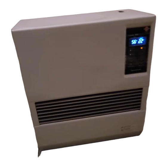
LASER CLEAN HEATING SYSTEM/VENTED HEATER
INSTALLATION AND OPERATION INSTRUCTIONS
LASER CLEAN VENTED
Laser 560
MODEL
(Type A)
IMPORTANT
READ AND UNDERSTAND INSTRUCTIONS BEFORE INSTALLING OR USING HEATER.
RETAIN INSTRUCTIONS FOR FUTURE REFERENCE. CHECK LOCAL CODES AND ORDINANCES FOR PERMITTED USE.
···················································· 5
················································ 2
·············································· 3
································ 4
················· 6
··········································· 9
················································· 10
···································· 15
···································· 16
CONTENTS
·············································· 8
Installation of Heater and Flue Pipe
························································ 33
·········································· 9
······················ 20
························· 20
········································ 22
·························· 25
··············· 26
······················· 32
Advertisement
Table of Contents

Related Manuals for Toyotomi Toyostove Laser 560


Summary of Contents for Toyotomi Toyostove Laser 560
-
Page 1: Table Of Contents
Laser 560_Type A_US.qxd 15.3.26 16:15 ページ 1 LASER CLEAN HEATING SYSTEM/VENTED HEATER INSTALLATION AND OPERATION INSTRUCTIONS LASER CLEAN VENTED Laser 560 MODEL (Type A) IMPORTANT READ AND UNDERSTAND INSTRUCTIONS BEFORE INSTALLING OR USING HEATER. RETAIN INSTRUCTIONS FOR FUTURE REFERENCE. CHECK LOCAL CODES AND ORDINANCES FOR PERMITTED USE. CONTENTS SECTION A: SECTION G:... -
Page 2: Section A
Laser 560_Type A_US.qxd 15.3.26 16:15 ページ 2 SECTION A: SPECIFICATIONS Model: Laser 560 Heater Efficiency: 92.4% (1) Heat Rating: High - 22,000 BTU/h Med - 15,000 BTU/h Low - 8,000 BTU/h Fuel Consumption: High - 0.165 gal/h (0.625 L/h) Med - 0.113 gal/h (0.428 L/h) Low - 0.060 gal/h (0.227 L/h) Fuel System: Gravity Fed from Reservoir / Tank (2) -
Page 3: Safety Features
Laser 560_Type A_US.qxd 15.3.26 16:15 ページ 3 SAFETY FEATURES Your Laser 560 is equipped with the following safety features. Please familiarize yourself with these features. When your heater is extinguished due to a safety mechanism, be sure to identify and correct the problem. Heat Circulation Heat shield plate... -
Page 4: Section B
Laser 560_Type A_US.qxd 15.3.26 16:15 ページ 4 SECTION B: SAFETY TIPS FOR OPERATION CAUTION: Heater and vent pipe system must be properly installed before operation. Please follow instructions under “Installation”, Section I. Never use any fuel other than clear or red colored kerosene (ASTM D3699 1-K RIGHT WRONG Kerosene, ASTM D396 Low Sulfur No.1 Fuel Oil, ASTM D975 Ultra Low Sulfur... -
Page 5: Section C
FUEL GUIDE The Toyostove Laser 560 is designed for use with ASTM D3699 1-K kerosene, ASTM D396 Low Sulfur No.1 Fuel Oil, ASTM D975 Ultra Low Sulfur Diesel (ULSD), or Ultra Low Sulfur Heating Oil (ULSHO). Use of low-quality fuel will cause burner performance to drop, leading to abnormal combustion and reduced heater life. -
Page 6: Section D
Laser 560_Type A_US.qxd 15.3.26 16:15 ページ 6 SECTION D: OPERATING CONTROLS AND PART NAMES Before using heater, familiarize yourself with the following operating controls and part names. Circulation fan motor 17. Circulation fan Fan cover 18. Room temperature Carrying handle sensor Control panel Red reset button... - Page 7 Laser 560_Type A_US.qxd 15.3.26 16:15 ページ 7 1. ON/OFF button: Main button turns heater on and off. When switched on, heater begins operation and combustion starts after preheat period. 2. AUTO button: The button turns weekly timer operation modes on and off which have been programmed into weekly timer.
- Page 8 Laser 560_Type A_US.qxd 15.3.26 16:16 ページ 8 82 81 81 82 RE. # PART # DESCRIPTION RE. # PART # DESCRIPTION RE. # PART # DESCRIPTION 20470446 Front panel assembly 20475971 Blower motor exhaust fan 20474039 Insulator A 20475804 Carrying handle 20475983 Blower motor intake fan 20474057...
-
Page 9: Section E
Laser 560_Type A_US.qxd 15.3.26 16:16 ページ 9 SECTION E: OPERATION BEFORE IGNITION 1. Open the Valve(s) Open the valve(s) of the external fuel tank. 2. Start the Fuel flow Red reset Button If using heater for the first time, press the red reset button in order to send fuel to the fuel sump and release. -
Page 10: Operation
Laser 560_Type A_US.qxd 15.3.26 16:16 ページ 10 3) Setting of a day of the week “dAy” sign is shown on the display and all of days of the week will blink. Press the “▲MIN.” button or the “▼HOUR” button to set a day of the week. A day of the week will blink. (Initial setting is “SUN”.) The other days of the week will go off. - Page 11 Laser 560_Type A_US.qxd 15.3.26 16:16 ページ 11 2. Adjusting Room Temperature A. Press “HOUR” or “MIN.” button. ˚F or ˚C will start to flash. Note: “HOUR” or “MIN.” button will change the temperature in increment of 2˚F (1˚C). B. Press “MIN.” for up and “HOUR” for down. Room temperature can be set from 50˚F (10˚C) to 90°F (32˚C). (Initial setting : 56˚F (13˚C)) C.
- Page 12 Laser 560_Type A_US.qxd 15.3.26 16:16 ページ 12 Approx. +10˚F Approx. +1˚F TEMP. High Medium Re-lgnition CHILD LOCK OPERATION Press the CHILD LOCK (CLEAR) button for more than 3 seconds to set the child lock while in operation or not in operation. “CHILD LOCK” sign will be shown on the digital indicator.
- Page 13 Laser 560_Type A_US.qxd 15.3.26 16:16 ページ 13 WEEKLY TIMER OPERATION 1. Set the Weekly Timer Note: The following programs are set at the factory in advance. Program # Clock Time Temp. AM 6:00 68˚F (20˚C) “MON” “TUE” “WED” “THU” “FRI” AM 8:30 62˚F (16˚C) “MON”...
- Page 14 Laser 560_Type A_US.qxd 15.3.26 16:16 ページ 14 2) Set the timer The timer is shown on the display. (In the case that the timer time is not set, dashes are shown on the display.) Press the “▲MIN.” button or the “▼HOUR” button to set timer time. “AM 12:00” will be shown on the display. (The all signs except the colon will blink.) When pressing the “▼HOUR”...
-
Page 15: Turning Heater Off
Laser 560_Type A_US.qxd 15.3.26 16:16 ページ 15 2. Activate Weekly Timer Operation During operation (in ON position), press the “AUTO” button to turn on the weekly timer operation mode. However, if no program are set, you will hear the beep sound and cannot turn on the weekly timer operation mode. Press the “▲MIN.” button or the “▼HOUR”... -
Page 16: Section F
Laser 560_Type A_US.qxd 15.3.26 16:16 ページ 16 SECTION F: ROUTINE MAINTENANCE CAUTION: Be sure to turn off and unplug heater before performing any checks or cleaning. CAUTION: Allow heater to cool completely before cleaning or maintenance. FOR OPTIMUM HEATER PERFORMANCE, THE PARTS SHOWN BELOW SHOULD BE CLEANED REGULARLY: Fan cover Louver Side door... - Page 17 Laser 560_Type A_US.qxd 15.3.26 16:16 ページ 17 Clean Fuel Strainer (ONCE A SEASON) Oil catch The strainer of the fuel sump should be cleaned once a season and before starting the heater at the beginning of each season. (a) Close the valve closest to the heater. (b) To catch the fuel which will drain out, set the Oil catch below the Strainer cover, with a small container under it.
-
Page 18: Section G
Laser 560_Type A_US.qxd 15.3.26 16:16 ページ 18 SECTION G: TROUBLESHOOTING NOTE BEFORE REQUESTING FOR REPAIR AND SERVICES The following symptoms are normal during operation of the heater. CONDITION REASON White smoke or smell at initial use after Machine oil or dust burns off of the surfaces the purchase. -
Page 19: Section H
Laser 560_Type A_US.qxd 15.3.26 16:16 ページ 19 SECTION H: LONG TERM STORAGE At the end of each heating season, or when you do not plan to use your heater for an extended period, the following procedures are recommended. As the end of the season approaches, calculate your fuel purchases so that you can use up all the fuel you have on hand. -
Page 20: Section I
Laser 560_Type A_US.qxd 15.3.26 16:16 ページ 20 SECTION I: INSTALLATION TOOLS NEEDED FOR INSTALLATION Tool Phillips Head Screwdriver Installation of flue pipe, etc. Electric Drill Drilling hole in wall for flue pipe Hole Saw, 2-3/4 to 3” diameter Making hole in wall for flue pipe STANDARD INSTALLATION PARTS The following standard installation parts are enclosed with heater. - Page 21 Laser 560_Type A_US.qxd 15.3.26 16:16 ページ 21 Flue Pipe (1) (PART #20479891) Exhaust Air Cap (1) (PART #20479845) Intake Air Cap (1) (PART #20474949) Spacer (1) (PART #20478967) Screw 4G (3) (PART #20474985) Screw M (3) (PART #20474272) 3-1/8” Bent Joint (1) (PART #20470484) L-Shaped Hose (2) (PART #20474975) Oil Catch (1) (PART #20474925) Hose Band (2) (PART #20474977)
-
Page 22: Accessary Parts
Laser 560_Type A_US.qxd 15.3.26 16:16 ページ 22 ACCESSORY PARTS The following accessory parts are available for use in non-standard installation of the Laser 560. After giving careful consideration to your desired heater and flue pipe locations and fueling system, consult your TOYOSTOVE dealer to purchase the necessary accessory parts. - Page 23 Laser 560_Type A_US.qxd 15.3.26 16:16 ページ 23 EXTENSION KIT Extension Pipe Kit (L) PART #20479898 INSTALLATION WITH EXTENSION PIPE KIT (L) Max. 39- ~ Min. 22- inch (# 20479861) (# 20474963) (# 20479853) (# 20474950) inch Pipe Support Hardware (# 20479872) Pipe Holder (2 pcs.) 80 inch Adjustable...
- Page 24 Laser 560_Type A_US.qxd 15.3.26 16:16 ページ 24 Extension Pipe Kit (M) PART #20479897 Extension Pipe Kit (S) PART #20479896 Max. 39- ~ Min. 22- inch Max. 19- ~ Min. 12- inch (# 20479861) (# 20474963) (# 20479861) (# 20474963) (# 20479853) (# 20479858) (# 20474950) (# 20474950)
-
Page 25: Safety Tips For Installation
Laser 560_Type A_US.qxd 15.3.26 16:16 ページ 25 SAFETY TIPS FOR INSTALLATION Follow the safety tips below when planning the installation of your Laser 560. Intake and exhaust flue pipe openings must be fully exposed to outside air. Do not vent into chimney, garage, basement under the floor, or into any enclosed area. Do not install flue pipe in close proximity to other objects or materials (See page 26). - Page 26 Laser 560_Type A_US.qxd 15.3.26 16:16 ページ 26 IMPORTANT: Check and comply with all state and local codes that may apply to vented heaters before beginning installation. NOTE: This heater is designed to be used at altitudes up to 3,000 ft. above sea level. For use at altitudes higher than 3,000 FT.
- Page 27 Laser 560_Type A_US.qxd 15.3.26 16:16 ページ 27 For standard installation, use the template enclosed with the heater to position the hole for the flue pipe. Tack or tape template to the wall at the desired position (See Fig. 4). Tape Fig.
- Page 28 Laser 560_Type A_US.qxd 15.3.26 16:16 ページ 28 Install the inner flue pipe. For wall thickness 5- ” to 9” From inside the room, insert the inner flue pipe through the hole. Make sure the arrow on the inner flue pipe is pointing up. Secure the inner flue pipe to the wall with the three wood screws. (See Fig.
- Page 29 Laser 560_Type A_US.qxd 15.3.26 16:16 ページ 29 6. Insert the bent joint to the exhaust opening of the flue pipe. Cut the inlet hose for desired length if necessary. Attach the L-shaped hose to each end of the inlet hose and attach the L-shaped hose to the intake opening of the flue pipe.
- Page 30 Laser 560_Type A_US.qxd 15.3.26 16:16 ページ 30 Move the heater into position. Connect the bent joint to the exhaust outlet opening (upper opening) and attach the L-shaped hose to the intake inlet opening. Make sure all connections are tight (See Fig. 12). Bent Joint Outlet Opening Inlet Opening...
- Page 31 Laser 560_Type A_US.qxd 15.3.26 16:16 ページ 31 10. Make sure the position of the heater is level by using the plumb bob located at the right side of the heater. The plumb bob weight should be within the circle. If the plumb bob weight is not within the circle, adjust the heater legs until the plumb bob weight is within the red circle (See Fig.
-
Page 32: Permanent Wiring Installation
Laser 560_Type A_US.qxd 15.3.26 16:16 ページ 32 PERMANENT WIRING INSTALLATION WARNING: MAKE SURE POWER SUPPLY CORD IS DISCONNECTED TO AVOID ANY ELECTRIC SHOCK BEFORE SERVICING. ELECTRIC SHOCK MAY CAUSE SERIOUS INJURY. INSTALLATION SHOULD BE CONDUCTED BY A LICENSED ELECTRICIAN. Step 1. Step 4. -
Page 33: Section J
Laser 560_Type A_US.qxd 15.3.26 16:16 ページ 33 SECTION J: FUELING WARNING: Use only ASTM D3699 1-K kerosene, ASTM D396 Low Sulfur No.1 Fuel Oil, ASTM D975 Ultra Low Sulfur Diesel (ULSD), or Ultra Low Sulfur Heating Oil (ULSHO). NEVER USE GASOLINE. Use of gasoline can lead to uncon- trollable flames resulting in destructive fire. - Page 34 Laser 560_Type A_US.qxd 15.3.26 16:16 ページ 34 Outdoor fuel tank Tank vent Laser 560 Fuel filter (1) 81/2ft.maximum 16in.minimum Shut off valve Shut-off valve 3/8in.OD copper tubing NOTE: Please check local codes for permitted use. (1) 15 or less Micron Filter is recommened.
- Page 35 Laser 560_Type A_US.qxd 15.3.26 16:16 ページ 35 CUSTOMER’S RECORD PROGRAM MANAGEMENT TABLE Monday (Tue.) Tuesday (Wed.) Wednesday (Thu.) Thursday (Fri.) Friday (Sat.) Saturday (Sun.) Sunday (Mon.) PROGRAM # TIME TEMPERATURE...
- Page 36 WHO IS COVERED : The original purchaser at retail. WHAT WE WILL DO : TOYOTOMI will either repair or replace, at its option, all defective parts free of charge that are covered by this limited warranty on a carry-in basis, to your nearest authorized dealer or distributor of TOYOTOMI.