National Instruments NI 5102 Getting Started Manual
Ni high-speed digitizers
Hide thumbs
Also See for NI 5102:
- Getting started manual (68 pages) ,
- Getting started manual (32 pages)
Table of Contents
Advertisement
Quick Links
GETTING STARTED GUIDE
NI High-Speed Digitizers
This document contains English and Japanese language instructions.
This document explains how to install, configure, and test NI high-speed digitizers and accessories,
and how to begin programming them using the NI-SCOPE instrument driver software. This document
applies to the following digitizers and accessories: NI 5102, NI 5105, NI 5112, NI 5114, NI 5122,
NI 5124, NI 5132, NI 5133, NI 5142, NI 5152, NI 5153, NI 5154, NI 5620, NI 5621, NI 5622, NI 5900,
NI 5911, and NI 5922.
For more information on features and programming, refer to the NI High-Speed Digitizers Help.
For device specifications, refer to the specifications document included with your device. Both
documents are available at Start»All Programs»National Instruments»NI-SCOPE»
Documentation.
For the most current versions of documentation, visit
NI-SCOPE, visit
Contents
Conventions ......................................................................................................................................... 2
1. Verifying System Requirements...................................................................................................... 3
2. Unpacking........................................................................................................................................ 3
3. Verifying the Kit Contents............................................................................................................... 3
Other Required Items................................................................................................................... 4
4. Installing the Software ..................................................................................................................... 4
5. Installing the Hardware.................................................................................................................... 5
PXI Modules ................................................................................................................................ 5
PXI Express Modules .................................................................................................................. 6
PCI Devices ................................................................................................................................. 7
USB Devices................................................................................................................................ 8
USB Cable Strain Relief ...................................................................................................... 9
Mounting the USB-513x.............................................................................................................. 10
Desktop Use......................................................................................................................... 10
DIN Rail Mounting.............................................................................................................. 10
Panel Mounting.................................................................................................................... 11
Windows Device Recognition ..................................................................................................... 11
6. Configuring and Testing in MAX.................................................................................................... 12
7. Programming the Device ................................................................................................................. 14
Acquiring Data Interactively ....................................................................................................... 14
Acquiring Data Programmatically ............................................................................................... 14
NI-SCOPE Examples................................................................................................................... 14
NI Example Finder............................................................................................................... 14
8. Making Your First Measurement..................................................................................................... 14
March 2009
371133M
.
ni.com/idnet
. For the latest version of
ni.com/manuals
Advertisement
Chapters
Table of Contents

Related Manuals for National Instruments NI 5102


Summary of Contents for National Instruments NI 5102
-
Page 1: Table Of Contents
NI-SCOPE instrument driver software. This document applies to the following digitizers and accessories: NI 5102, NI 5105, NI 5112, NI 5114, NI 5122, NI 5124, NI 5132, NI 5133, NI 5142, NI 5152, NI 5153, NI 5154, NI 5620, NI 5621, NI 5622, NI 5900, NI 5911, and NI 5922. -
Page 2: Conventions
NI 5152/5153/5154 Front Panels... 20 NI 5622 Front Panels ... 21 Appendix B: Front Panels for Traditional NI-DAQ (Legacy) Devices... 22 NI 5102 Front Panels ... 22 NI 5112 Front Panels ... 25 NI 5620/5621 Front Panels ... 26 NI 5911 Front Panel... 27 Appendix C: Accessory Front Panels ... -
Page 3: Verifying System Requirements
NI LabVIEW SignalExpress CD (USB devices only) Note SMC-based devices are based on the National Instruments Synchronization and Memory Core architecture. These include the NI 5105, NI 5114, NI 5122, NI 5124, NI 5142, NI 5152, NI 5153, NI 5154, NI 5622, and NI 5922. For more information, refer to the NI High-Speed Digitizers Help. -
Page 4: Other Required Items
Other Required Items In addition to the items contained in the kit, you need the following items: ❑ 1/8 in. flat-head screwdriver ❑ One of the following configurations: – (PXI Devices) A PXI chassis, a PXI/SCXI combination chassis, or a PXI/CompactPCI chassis with a controller and the chassis documentation (PXI Express Devices) –... -
Page 5: Installing The Hardware
Before operating the module, cover all empty PXI slots using PXI filler panels or slot blockers, which you can purchase at 10. Plug in and power on the PXI chassis. © National Instruments Corporation ni.com NI High-Speed Digitizers Getting Started Guide... -
Page 6: Pxi Express Modules
PXI Chassis Ejector Handle in Downward Position PXI Express Modules Follow the installation instructions in the slot of the chassis. Refer to the chassis documentation for information about the markings that denote PXI Express slots. PXI Express Chassis Ejector Handle NI High-Speed Digitizers Getting Started Guide Figure 1. -
Page 7: Pci Devices
Multiple NI 5911 devices in the same computer can raise operating temperatures beyond specification and produce imprecise data. NI strongly recommends leaving an empty PCI slot between multiple NI 5911 devices or adding a fan. © National Instruments Corporation PCI Slot Figure 3. PCI Installation Figure 4. -
Page 8: Usb Devices
Secure the device to the PCI chassis with a screw. Caution It is important to completely screw the device front panel into the PCI slot, both for mechanical stability and to create a solid ground connection. Improperly secured devices may affect the accuracy of the device. -
Page 9: Usb Cable Strain Relief
1 Groove Method 2 Zip Tie Method 3 USB Cable Strain Relief Groove (Large) 4 USB Cable Strain Relief Groove (Small) © National Instruments Corporation Figure 6. USB Cable Strain Relief Options 5 USB Cable 6 Zip Tie 7 Zip Tie Bar... -
Page 10: Mounting The Usb-513X
Mounting the USB-513x You can use the USB-513x on a desktop or mount it to a standard DIN rail or a panel. Desktop Use The USB-513x has plastic guides on the underside that allow it to be stacked on top of other USB-513x devices. -
Page 11: Panel Mounting
NI device installed. Install the software automatically (Recommended) is selected by default. Click Next or Yes to install the software for each device. © National Instruments Corporation Figure 8. Mounting the USB-513x on a Panel USB Cable Strain Relief... -
Page 12: Configuring And Testing In Max
Note (USB devices) device. Click Next on any dialog boxes that appear to complete the installation. After Windows recognizes newly installed device, a dialog box prompts you to select from the following options, which may vary depending on the devices and software installed on your system: •... - Page 13 (SFP). However, only NI-DAQmx devices can be self-calibrated using MAX. Exit MAX when you have finished configuring and testing the digitizer. © National Instruments Corporation Select the device to see its properties in the configuration , where n is the device number MAX assigned to your device. NI-SCOPE The assigned device name is appended to the device in its configuration "...
-
Page 14: Programming The Device
Soft Front Panel. The NI-SCOPE SFP provides context-sensitive help for its controls. Acquiring Data Programmatically You can use NI-SCOPE to begin programming the digitizer in your ADE. Refer to the Programming section of the NI High-Speed Digitizers Help at Start»All Programs»National Instruments» NI-SCOPE»Documentation. NI-SCOPE Examples Programming examples for using NI-SCOPE with LabVIEW, LabWindows on the NI-SCOPE CD. -
Page 15: Appendix A: Front Panels For Smc-Based Devices And Usb Devices
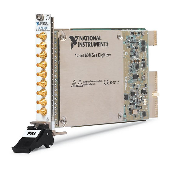
Table 1 describes the signal connections for the NI 5105. Connector CH 0 to CH 7 Standard SMB jack connector PFI 1 Standard SMB jack connector © National Instruments Corporation NI PXI-5105 NI PCI-5105 12-Bit 60 MS/s Digitizer CH 0 CH 0... -
Page 16: Ni 5114 Front Panels
NI 5114 Front Panels Figure 11 shows the NI PXI-5114 and NI PCI-5114 front panels. For the AUX connector pinout information, refer to Figure 13. Table 2 describes the signal connections for the NI 5114. Connector CH 0, Standard BNC female CH 1 connector TRIG... -
Page 17: Ni 5122/5124/5142/5922 Front Panels
TRIG Standard BNC female connector CLK IN Standard SMB jack connector © National Instruments Corporation Figure 12. NI 5122/5124/5142/5922 Front Panels Description Analog input connection; digitizes data and triggers acquisitions. External analog trigger connection; signals on the TRIG connector cannot be digitized. - Page 18 Table 3. NI 5122/5124/5142/5922 Front Panel Signal Connections (Continued) Connector CLK OUT Standard SMB jack connector AUX I/O 9-pin mini-circular DIN connector Figure 13 shows the pin assignments for the 9-pin DIN connector. +5 V (Fused) Reserved Figure 13. 9-Pin DIN Connector Pin Assignments for NI 5114/5122/5124/5142/5922 NI High-Speed Digitizers Getting Started Guide Description NI 5122/5124/5142: Output for the reference clock or sample...
-
Page 19: Ni 5132/5133 Front Panels
Figure 15 shows the NI 5132/5133 back panel. Recessed USB port Table 4 describes the signal connections for the NI 5132/5133. Connector CH 0, CH 1 PFI 1 © National Instruments Corporation CH 0 CH 1 PFI 1 CH 0 CH 1 PFI 1 Figure 14. -
Page 20: Ni 5152/5153/5154 Front Panels
NI 5152/5153/5154 Front Panels Figure 16 shows the NI PXI-5152/5153/5154 and NI PCI-5152/5153/5154 front panels. Table 5 describes the signal connections for the NI 5152/5153/5154. Table 5. NI 5152/5153/5154 Front Panel Signal Connections Connector CH 0, Standard BNC female CH 1 connector TRIG Standard BNC female... -
Page 21: Ni 5622 Front Panels
Figure 17 shows the NI PXIe-5622 front panels. Table 6 describes the signal connections for the NI 5622. Connector IF IN PFI 1 CLK IN CLK OUT © National Instruments Corporation NI PXIe-5622 16-Bit IF Digitizer ACCESS ACTIVE IF IN PFI 1... -
Page 22: Appendix B: Front Panels For Traditional Ni-Daq (Legacy) Devices
NI-DAQ (Legacy) devices: NI 5102, NI 5112, NI 5620/5621, and NI 5911. NI 5102 Front Panels The NI 5102 is available for PXI and PCI platforms. This section describes the front panels and signal connections for both types of NI 5102 digitizers. - Page 23 Note The +5 V signal is fused at 1.1 A. However, NI recommends limiting the current from this pin to 30 mA. The fuse is self-resetting. © National Instruments Corporation Table 7. NI PXI-5102 Front Panel Signal Connections Description Analog input connection; digitizes data and triggers acquisitions.
- Page 24 Standard SMB jack connector PFI 2 Standard SMB jack connector Note When used as inputs, NI 5102 PFI lines can trigger an acquisition and/or allow an external sample clock connection. NI High-Speed Digitizers Getting Started Guide CH 0 CH 1 TRIG...
-
Page 25: Ni 5112 Front Panels
TRIG Standard BNC female connector PFI 1 Standard SMB jack connector 9-pin mini-circular DIN connector © National Instruments Corporation NATIONAL INSTRUMENTS NI PXI-5112 100 MHz Digital Oscilloscope PFI 1 Figure 21. NI 5112 Front Panels Table 9. NI 5112 Front Panel Signal Connections Description Analog input connection;... -
Page 26: Ni 5620/5621 Front Panels
NI 5620/5621 Front Panels Figure 22 shows the NI PXI-5620/5621 front panels. Table 10 describes the signal connections for the NI 5620/5621. Connector INPUT Standard SMA female connector REF CLK IN Standard SMA female connector PFI 1 Standard SMB jack connector NI High-Speed Digitizers Getting Started Guide NI PXI-5620... -
Page 27: Ni 5911 Front Panel
Standard BNC female connector PFI 1 Standard SMB jack connector PFI 2 (AUX) 9-pin mini-circular DIN connector © National Instruments Corporation CH 0 PFI 1 PFI 2 Figure 23. NI 5911 Front Panel Table 11. NI 5911 Front Panel Signal Connections Description Analog input connection;... -
Page 28: Appendix C: Accessory Front Panels
Appendix C: Accessory Front Panels This appendix describes the front panel and signal connections for the digitizer accessory. NI 5900 Front Panel Figure 24 shows the NI PXI-5900 differential amplifier front panel and the connections to the NI 5922. Table 12 describes the signal connections for the NI 5900. Connector CH 0+ Standard BNC female connector... -
Page 29: Appendix D: Troubleshooting
If the device is still not listed, power off the system, verify that the device is correctly installed, and restart. If the device still does not appear under Devices and Interfaces, contact NI Technical Support at ni.com/support © National Instruments Corporation 5. Installing the 6. Configuring and Testing in 5. Installing the 6. -
Page 30: Device Failed The Self-Test
If the software optimization application is not installed on your system, use the MXI software CD or the National Instruments Driver CD included with your kit to install the software. After installation, you may need to restart your computer before running the MXI Optimization Application. -
Page 31: Ni 5112 Programming Practices
National Instruments corporate headquarters is located at 11500 North Mopac Expressway, Austin, Texas, 78759-3504. National Instruments also has offices located around the world to help address your support needs. For telephone support in the United States, create your service request at and follow the calling instructions or dial 512 795 8248. - Page 32 National Instruments, NI, ni.com, and LabVIEW are trademarks of National Instruments Corporation. Refer to the Terms of Use section on ni.com/legal for more information about National Instruments trademarks. Other product and company names mentioned herein are trademarks or trade names of their respective companies. For patents covering National Instruments products/technology, refer to the appropriate location: Help»Patents in your software, the patents.txt file on your media, or the National Instruments Patent Notice at ni.com/patents.
- Page 33 付録 対応デバイスおよび NI 5105 のフロントパネル NI 5114 のフロントパネル NI 5122/5124/5142/5922 NI 5132/5133 フロントパネル 2009 年 月 371133M 高速デジタイザおよびアクセサリの取り付け、構成、テスト、 NI 5102 NI 5105 NI 5112 、 、 、 NI 5152 NI 5153 NI 5154 、 、 、 NI 5922 に適用します。 高速デジタイザヘルプ』を参照してくだ...
-
Page 34: 表記規則
NI 5152/5153/5154 NI 5622 のフロントパネル NI-DAQ 付録 従来型 NI 5102 のフロントパネル NI 5112 のフロントパネル NI 5620/5621 フロントパネル NI 5911 フロントパネル 付録 アクセサリのフロントパネル NI 5900 フロントパネル 付録 トラブルシューティング PXI/PXI Express モジュールのフロントパネル モジュールが接続されていても ... 30 が点灯しない デバイスが デバイスがセルフテストで不合格になる ... 31 過熱遮断エラー 接続時におけるパフォーマンスの問題... -
Page 35: システム要件を確認する
デバイス仕様書 – はじめにお読みください – 『 高速デジタイザスタートアップガイド』 (本書) – 『強制空冷の維持について』 ( – スペクトル計測ツールキット デバイスのみ) – ケーブル( – NI LabVIEW SignalExpress CD © National Instruments Corporation NI-SCOPE ドライバと一緒に使用するには、特定の要件を満たすシス NI-SCOPE Readme NI-SCOPE → →ドキュメントを選択して『 )防止のため静電気防止用袋に梱包されて出荷さ 高速デジタイザまたはアクセサリ を含む、 安全対策と電磁両立性について 対応デバイスのみ) (メモリオプションが デバイスのみ) ( デバイスのみ)... -
Page 36: その他必要となるもの
メモ 対応デバイスは、ナショナルインスツルメンツ and Memory Core NI 5105 NI 5114 、 、 NI 5922 および が含まれます。詳細については、 『 てください。 その他必要となるもの キットに含まれるアイテム以外に、以下が必要となります。 ❑ 1/8 in. マイナスドライバー ❑ 以下のうちいずれか – ( デバイス) PXI/CompactPCI – PXI Express ( キュメント – ( デバイス) – ( デバイス) メモ... -
Page 37: ハードウェアを取り付ける
シャーシを配置する際は、吸排気口が遮蔽されないよう注意します。 詳細について は、各シャーシのドキュメントを参照してください。 着脱用ハンドルがラッチされていない状態(下向き)になっていることを確認します。 モジュールの脱着ハンドル部分を持ち、図 トに差し込みます。 モジュールの底部がシャーシのガイドに固定されていることを確認 します。 モジュールを完全にシャーシに押し込み、脱着ハンドルを引き上げて固定します。 モジュールのフロントパネルの上下を取り付けネジで固定します。 両方のネジが適切に 締められていないと、パフォーマンスに影響が出る恐れがあります。 8. PXI シャーシファンが動作し、通気を妨げるようなほこりや汚れがついていないことを 確認します。 モジュールを動作する前に、 ( で購入可能)を使用して、すべての空の ni.com/jp い。 10. PXI シャーシの電源ケーブルのプラグを差し込み、電源を入れます。 © National Instruments Corporation PXI/PXIe 、 、および プラットフォームのハードウェアを取 シャーシの電源を切り、プラグを抜きます。 のようにモジュールを空いているスロッ フィラーパネルまたはスロットブロッカー スロット HIGH に設定します。 スロットに取り付けてくださ 高速デジタイザ スタートアップガイド... -
Page 38: Pxi Express モジュール
シャーシ 脱着ハンドル(下向きになっていること) PXI Express モジュール 「 モジュール」セクションの取り付け手順に従って、モジュールをシャーシの PXI Express スロットに取り付けます。 シャーシのドキュメントを参照してください。 PXI Express シャーシ 脱着ハンドル デバイス デバイスを取り付けるには、以下の手順に従ってください。 コンピュータの電源を切り、電源プラグを抜きます。 2. PC のカバーを外します。 高速デジタイザ スタートアップガイド 図 モジュールの取り付け PXI Express スロットを示す表記については、 ネジ NI PXI Express モジュール PXI Express 図 モジュールの取り付け ネジ NI PXI モジュール... - Page 39 NI PCI-5911 ( ) ムの中央に位置していることを確認します。 タのカバーに接触している場合、信号の劣化を招く恐れがあります。 ノイズを最小限に 抑えるために、 ださい。 NI 5911 複数の デバイスを同一のコンピュータに取り付けると、仕様に記載されている 動作温度を上回り、データの精度が低下する場合があります。 そのため、複数の NI 5911 デバイスを使用する場合には、 けるか、ファンを追加してください。 デバイスを シャーシにネジで固定します。 © National Instruments Corporation スロットにデバイスを差し込みます。 スロット 図 の取り付け を取り付ける際、 コネクタが図 コネクタの外部シェルがコンピュー コネクタが の金属部分に触れることがないように注意してく NI PCI-5911 図 の取り付け つの スロットを空けてデバイスを取り付 ス...
-
Page 40: Usb デバイス
注意 デバイスのフロントパネルは必ず は、機械的な安定性と確実な接地接続を確保するために重要です。 デバイスを適切に固定 しないと、デバイスの確度に影響する場合があります。 ( 対応デバイス) プラスチックのレバーを使用するものもあります。このような場合、レバーは使用せず に、取り外す必要があります。 キットに含まれているネジを使用してデジタイザを固定 してください。 ネジで固定することができない場合は、別のコンピュータシャーシを使 用する必要があります。 5. PC のカバーを元どおりに取り付けます。 コンピュータの電源プラグを差し込み、電源を投入します。 ( 対応デバイス) します。 確認する方法については、 メモ 対応デバイスでは、拡散スペクトルクロックは、タイミングクロック信号が 狭い周波数範囲全体に渡るよう、クロック信号を分散します。 拡散スペクトルクロックを 無効にすると、デバイスの確度に影響が出る可能性があります。 デバイス デバイスを取り付けるには、図 続します。 ノートブック 高速デジタイザ スタートアップガイド スロットにネジで固定してください。これ コンピュータの種類によっては、 拡散スペクトルクロックが のドキュメントを参照してください。 のように NI USB 高速デジタイザ 図... -
Page 41: Usb ケーブルストレインリリーフ
ケーブルストレインリリーフ ケーブルには、以下の • : USB 固定溝を使用 込みます。 図 のように、 • ケーブルタイを使用 バーにケーブルタイを通し、 固定溝を使用 ケーブルタイを使用 ケーブルストレインリリーフ用溝(大) ケーブルストレインリリーフ用溝(小) 図 © National Instruments Corporation つのストレインリリーフオプションがあります。 ケーブルを、 デバイスの下側にある ケーブルのサイズに一致する溝を使用します。 図 のように、 デバイスの下側にあるケーブルタイ取り付け ケーブルを固定します。 ケーブルストレインリリーフオプション つの溝のいずれかに押し ケーブル ケーブルタイ ケーブルタイ取り付けバー 高速デジタイザ スタートアップガイド... -
Page 42: Usb-513X を取り付ける
を取り付ける USB-513x をデスクトップで使用、または標準 できます。 デスクトップでの使用 USB-513x には、複数の チックガイドが下部にあります。 デスクトップで使用する場合にデバイスを安定させるには、図 め用の脚をデバイスの下側に貼り付けます。 USB-513x メモ をパネルに取り付ける場合、または他の 重ねる場合は、ゴム脚は使用しないでください。 NI USB 高速デジタイザ レールマウント レールマウントキット(製品番号 USB-513x は、 製品群を標準 メモ 「 ケーブルストレインリリーフ」セクションの説明どおり、 レールに取り付ける前に、ストレインリリーフ対策を行います。 高速デジタイザ スタートアップガイド レールまたはパネルに取り付けることが USB-513x デバイスを積み重ねて使用することができるようにプラス プラスチックガイド USB-513x 図 ゴム脚を に取り付ける : 779689-01 USB-513x 、 レールに取り付けるためのアクセサリです。... -
Page 43: パネルに取り付ける
ウンロードして印刷します。 技術サポートデータベースのドキュメントを参照するに は、 ni.com/info テンプレートを使用して、パネル上下に印を付けます。 印は、 隔です。 3. USB ケーブルを 4. #8 または ネジをパネルの下の位置にネジ止めします。 5. USB-513x の下にあるネジ穴に合わせて、 6. #8 または ネジを © National Instruments Corporation USB-513x 図 をパネルに取り付ける USB-4065/5132/5133/6509 Panel 」に添付されているパネル取り付け用テンプレートの で のコードを入力します。 rd3233 USB-513x のコネクタから外します。 USB-513x USB-513x 上部のネジ穴に挿入してパネルに固定します。 を参照しながら以下の手順に従っ... -
Page 44: Windows のデバイス認識
Windows のデバイス認識 ハードウェアの取り付け後に初めてコンピュータを起動すると、 取り付けられたデバイスが認識されます。 一部の すべての デバイスに対して、 「新しいハードウェアの検索」ウィザードが起動します。 デ フォルトでは、デバイスに最適なドライバを検索する(推奨)が選択されています。 次へま たははいをクリックして、各デバイスのソフトウェアをインストールします。 メモ ( デバイス) デバイスを認識します。 表示されるダイアログボックスで次へをクリックし、インストー ルを完了します。 Windows が新しく取り付けられたデバイスを認識すると、以下のオプションを選択するた めのダイアログボックスが表示されます。表示されるオプションは、システムにインストー ルされているデバイスとソフトウェアによって異なります。 • NI LabVIEW SignalExpress LabVIEW SignalExpress • このデバイスを対話的に使用するを選択すると ( )が開きます。 • このデバイスでアプリケーションを開始するを選択すると • デバイスを構成しテストするを選択すると、 ます。 • 何もしないを選択すると、デバイスの認識状態は維持されますが、アプリケーションは 起動しません。 6. - Page 45 イスのプログラミング時に必要となります。 • NI-DAQ (従来型 ビューに表示します。 デバイス番号が値の列に表示されます。 デフォルトでは、デ バイスのリソース名は、 デバイス番号)です。 従来型 LabVIEW Real-Time • NI-DAQmx ( スに追加されます。 たとえば、デジタイザをインストールした場合、デバイスツ リー構図ラベルには デバイス名) 。 アプリケーションを開発する際、 © National Instruments Corporation NI-DAQ デバイスおよび従来型の 図 のツリー構図 モジュールと共にデジタイザを使用している場合、 <F5> を押して画面を更新します。 それでも表示 ハードウェアを取り付ける」のセクションの手順を再度繰り返し の使用方法については、 では、サポートされていない従来型 』を参照してください。 デバイスを選択して、プロパティを構成 (レガシー)デバイス) ( n は...
-
Page 46: デバイスをプログラミングする
デバイスを右クリックし、プロパティを選 (レガシー)デバイス) デバイスを右クリックして、セルフテストを選択します。 (レガシー)デバイス) デバイスを右クリックして、テストパネルを選択します。 ) を使用してプログラミングする方法と、 つの方法でこの機能を実行できます。 ただし、 NI-DAQmx を終了します。 NI-SCOPE NI-SCOPE ソフトフロントパネルを選択します。 NI-SCOPE デバイス名を右クリックして名前 NI-DAQ (レガシー)のデバ 高速デジタイザヘル 」関数または niScope_init 「 ハードウェアを取り付け )を参照して ni.com/support/jp プロパティウィンドウでテストパネル NI-SCOPE ソフトフロントパ でセルフ 対応デバイスのみとなります。 計測器ドライバを使用したプロ のサンプルを実行して、デジタ National Instruments NI-SCOPE SFP では、各制御器に デバ → ni.com/jp... -
Page 47: プログラムでデータを集録する
「 での構成とテスト」のセクション • 高速デジタイザヘルプ→プログラミング→リファレンス→ リファレンス→ • 高速デジタイザヘルプ→プログラミング→リファレンス→ Reference Help 入力信号を集録する際に、必要に応じてパラメータを調整します。 集録する信号を、デジタイザの入力チャンネルの ついては、 「付録 NI-DAQ 「付録 従来型 い。 サンプルプログラムを実行します。 © National Instruments Corporation NI-SCOPE NI-SCOPE → /CVI 、 で使用可能な NI-SCOPE → 』を参照してください。 CVI 7.1 以降のユーザは、 NI-SCOPE NI-SCOPE で使用できる NI-SCOPE (高速デジタイザ National Instruments... -
Page 48: 付録 A: Smc 対応デバイスおよび Usb デバイスのフロントパネル
A: SMC 付録 対応デバイスおよび この付録では、 NI 5124 NI 5132 NI 5133 、 、 NI 5922 デジタイザのフロントパネルと信号接続について説明します。 NI 5105 のフロントパネル NI PXI-5105 図 は、 NI 5105 表 は、 の信号接続を示します。 コネクタ CH 0 CH 7 ~ PFI 1 高速デジタイザ スタートアップガイド デバイスのフロントパネル 対応デバイスおよび デバイス... -
Page 49: Ni 5114 のフロントパネル
の信号接続を示します。 コネクタ CH 0 CH 1 、 メスコネクタ(標準) TRIG メスコネクタ(標準) CLK IN コネクタ(標準) AUX I/O ピンミニサーキュラ コネクタ © National Instruments Corporation NI PCI-5114 および のフロントパネルを示します。 を参照してください。 NI PXI-5114 CH 0 CH 0 CH 1 CH 1 TRIG TRIG CLK IN... -
Page 50: Ni 5122/5124/5142/5922 フロントパネル
NI 5122/5124/5142/5922 NI PXI-5122/5124/5142/5922 図 は、 NI PXI-5122 ネルを示します。 図 NI 5122/5124/5142/5922 表 は、 3 NI 5122/5124/5142/5922 表 コネクタ CH 0 、 メスコネクタ(標準) CH 1 TRIG メスコネクタ(標準) CLK IN コネクタ(標準) 高速デジタイザ スタートアップガイド フロントパネル NI PCI-5122/5124/5142/5922 および NI PXIe-5122 および のフロントパネルは同じです。 NI 5122/5124/5142/5922 の信号接続を示します。... - Page 51 コネクタ CLK OUT コネクタ(標準) AUX I/O ピンミニサーキュラ コネクタ ピン コネクタピンの割り当ては、図 +5 V ( ヒューズ付き 予約済み NI 5114/5122/5124/5142/5922 図 © National Instruments Corporation フロントパネルの信号接続 (続き) 説明 NI 5122/5124/5142: ロック出力。 NI 5922: 基準クロック出力。 汎用デジタルタイミング PFI 1 よび へのアクセス(別途ケーブルが必要) 。 ピン 配列に関する情報については、図 のとおりです。...
-
Page 52: Ni 5132/5133 フロントパネル
NI 5132/5133 フロントパネル NI USB-5132 図 は、 NI USB-5132 NI USB-5133 NI 5132/5133 図 は、 埋め込み式 ポート NI 5132/5133 表 は、 コネクタ CH 0 、 標準 CH 1 PFI 1 標準 高速デジタイザ スタートアップガイド NI USB-5133 および のフロントパネルを示します。 CH 0 CH 1 PFI 1 CH 0 CH 1... -
Page 53: Ni 5152/5153/5154 フロントパネル
NI 5152/5153/5154 表 は、 表 コネクタ CH 0 、 CH 1 TRIG PFI 0 コネクタ(標準) PFI 1 コネクタ(標準) © National Instruments Corporation NI PCI-5152/5153/5154 および ACCESS ACTIVE CH 0 TRIG TRIG CH 1 PFI 0 PFI 1 PFI0 PFI1 NI 5152/5153/5154 図... -
Page 54: Ni 5622 のフロントパネル
NI 5622 のフロントパネル NI PXIe-5622 図 は、 NI 5622 表 は、 の信号接続を示します。 コネクタ 説明 IF IN コネクタ PFI 1 コネクタ CLK IN コネクタ CLK OUT コネクタ 高速デジタイザ スタートアップガイド のフロントパネルを示します。 NI PXIe-5622 16-Bit IF Digitizer ACCESS ACTIVE IF IN PFI 1 CLK IN CLK OUT TTL (+5 V MAX) -
Page 55: Ni-Daq
NI 5102 のフロントパネル NI 5102 には、 と NI 5102 両方の デジタイザのフロントパネルと信号接続について説明します。 NI PXI-5102 図 は、 ( ) 列情報については、図 © National Instruments Corporation (レガシー)用デバイスのフロントパネル NI-DAQ (レガシー)デバイス プラットフォームがあります。 このセクションでは、 NI PXI-5102 のフロントパネルを示します。 を参照してください。 NI 5102 PFI 1 NI PXI-5102 図 フロントパネル NI 5102... - Page 56 NI PXI-5102 表 は、 コネクタ CH 0 、 CH 1 TRIG PFI 1 コネクタ(標準) ピンミニサーキュラ コネクタ NI PXI-5102 の ピン +5 V ( ヒューズ付き 予約済み NI PXI-5102 図 +5 V メモ 信号には 30 mA を 以内に制限して使用してください。 このヒューズはセルフリセット型です。 高速デジタイザ スタートアップガイド の信号接続を示します。 7 NI PXI-5102 表...
- Page 57 ( ) NI PCI-5102 表 は、 コネクタ CH 0 、 CH 1 TRIG PFI 1 PFI 2 NI 5102 PFI メモ クロック接続が可能となります。 © National Instruments Corporation NI PCI-5102 のフロントパネルを示します。 CH 0 CH 1 TRIG PFI 1 PFI 2 NI PCI-5102 図...
-
Page 58: Ni 5112 のフロントパネル
NI 5112 のフロントパネル NI PXI-5112 図 は、 ン配列情報については、図 NI 5112 表 は、 の信号接続を示します。 コネクタ CH 0 、 CH 1 TRIG PFI 1 ピンミニサーキュラ コネクタ 高速デジタイザ スタートアップガイド NI PCI-5112 および のフロントパネルを示します。 を参照してください。 NATIONAL INSTRUMENTS NI PXI-5112 100 MHz Digital Oscilloscope PFI 1 NI 5112 図... -
Page 59: Ni 5620/5621 フロントパネル
NI 5620/5621 表 は、 コネクタ INPUT メスコネクタ(標準) REF CLK IN メスコネクタ(標準) PFI 1 コネクタ(標準) © National Instruments Corporation のフロントパネルを示します。 NI PXI-5620 NI PXI-5621 64 MS/s Digitizer 64 MS/s Digitizer INPUT +20 dBm MAX +20 dBm MAX ±2 VDC MAX REF CLK IN... -
Page 60: Ni 5911 フロントパネル
NI 5911 フロントパネル NI PCI-5911 図 は、 については、図 を参照してください。 NI 5911 表 は、 の信号接続を示します。 コネクタ CH 0 メスコネクタ(標準) PFI 1 コネクタ(標準) PFI 2 (AUX) ピンミニサーキュラ コネクタ 高速デジタイザ スタートアップガイド のフロントパネルを示します。 CH 0 PFI 1 PFI 2 NI 5911 図 フロントパネル 11 NI 5911 表... -
Page 61: C: アクセサリのフロントパネル
メスコネクタ(標準) CH 0 OUT コネクタ(標準) CH 1+ メスコネクタ(標準) CH 1– メスコネクタ(標準) CH 1 OUT コネクタ(標準) © National Instruments Corporation 差動アンプのフロントパネルおよび NI PXI-5900 NI PXI-5922 CH 0 + CH 0 - OUT 0 CH 1 + CH 1 - OUT 1 NI 5900 図... -
Page 62: D: トラブルシューティング
付録 トラブルシューティング PXI/PXI Express シャーシの電源を入れても ACCESS LED ロントパネル PXI/PXIe シャーシの電源を投入してもデジタイザの PXI/PXIe の電源レール、ハードウェアデバイス、 ります。 メモ は、 この問題のトラブルシューティングを開始する前に、 か確認してください。 この問題のトラブルシューティングは、以下の手順で行ってください。 シャーシの電源を切ります。 2. PXI モジュールのフロントパネルへの信号接続をすべて取り外します。 3. PXI モジュールをシャーシから取り外し、破損がないか確認します。 破損しているデバ イスは再度取り付けないでください。 「 ハードウェアを取り付ける」セクションの説明に従って、 り付けます。 5. PXI シャーシの電源を投入します。 デバイスが でデバイスをリセットし、セルフテストを実行します。 ト、セルフテストする方法については、 照してください。 上記の手順を行っても ツの技術サポート( モジュールが接続されていても しない... -
Page 63: Max
– maximum amount of time exceeded – internal software error ソフトウェアを最適化するアプリケーションがシステムにインストールされていない場 合は、 ソフトウェア からインストールしてください。 終了後に、コンピュータの再起動を必要とする場合があります。 • MXI-4 MXI-Express ( および © National Instruments Corporation NI-DAQmx デバイスをクリックして )にお問い合わせください。 ni.com/jp/support に進んでください。 )にお問い合わせください。 シャーシの制御時にパフォーマンスの低下や初期化に関す のドキュメントを参照して を選択します。 このアプリケーションを実行せずに (タイムアウトエラー) (内部ソフトウェアエラー) またはキットに付属する MXI Optimization Application 最適化は、ハードウェアによって自動的に実行されます。... -
Page 64: 同期を行うための Smc 対応デバイスの設定
上記の手順を行っても初期化やパフォーマンスに問題がある場合は、スタート→すべてのプ National Instruments MXI ログラム→ ショナルインスツルメンツの技術サポートのウェブサイト( してください。 同期を行うための メモ 対応デバイスで同期( 順を行う必要があります。 ログラミング→リファレンス→ NI 5105/5114/5122/5124/5142/5152/5153/5154/5622/5922 デバイス( ためにトリガやクロックを共有する場合は、 あります。 PXIe ( および モジュール) する必要があります。 のツリー構図で a. PXI システム→次のモデルとして識別を右クリックします。 一覧からコントローラを選択します。 たとえば、 する場合は、 「外部 2. PXI システムツリーを展開し、使用するシャーシの名前を右クリックします。 以下の手順に従って ( デバイス) デバイス間を 2. MAX のツリー構図で... -
Page 65: E: サポート情報
32 (0) 2 757 0020, ベルギー 351 210 311 210, ポルトガル 27 0 11 805 8197, 南アフリカ 961 (0) 1 33 28 28, レバノン © National Instruments Corporation では、トラブルシューティングやアプリケーション開発のセ からその製品の 11500 North Mopac Expressway, Austin, 03-5472-2970 (フリーダイヤル)または 39 02 41309277, イタリア... - Page 68 Terms of Use の商標の詳細については、 ni.com/legal の「 」セクションを参照してください。本文書中に記載されたその他の製品名およ National Instruments び企業名は、それぞれの企業の商標または商号です。 の製品 技術を保護する特許については、ソフトウェアで参照できる特許情報 National Instruments Patent Notice ヘルプ→特許情報 、メディアに含まれている patents.txt ファイル、または「 」 ( ni.com/patents )のうち、該当する リソースから参照してください。 37xxxxX-0112 2009 年 月 © 2003–2009 National Instruments Corporation. All rights reserved Printed in <Country>.