Table of Contents
Advertisement
Quick Links
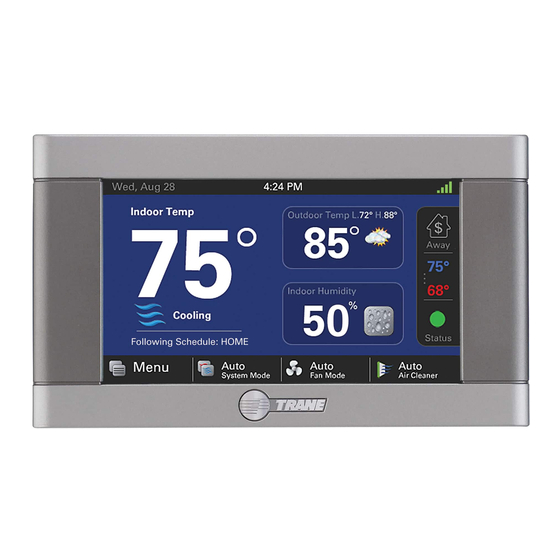
ComfortLink™ II XL 850
Communicating Connected Control
TCONT850 Installation Guide
ALL phases of this installation must comply with NATIONAL, STATE AND LOCAL CODES
IMPORTANT — This Document is customer property and is to remain with this unit.
These instructions do not cover all variations in systems or provide for every possible contingency to be met in connection with
the installation. Should further information be desired or should particular problems arise which are not covered sufficiently
for the purchaser's purposes, the matter should be referred to your installing dealer or local distributor.
18-HD73D1-9E-EN
Advertisement
Table of Contents

Related Manuals for Trane TCONT850


Summary of Contents for Trane TCONT850
- Page 1 ComfortLink™ II XL 850 Communicating Connected Control TCONT850 Installation Guide ALL phases of this installation must comply with NATIONAL, STATE AND LOCAL CODES IMPORTANT — This Document is customer property and is to remain with this unit. These instructions do not cover all variations in systems or provide for every possible contingency to be met in connection with the installation.
-
Page 2: Table Of Contents
Installation Guide Contents 1. Safety ..............2 Quiet Mode ..........15 2. Product Specifications .......... 3 6.10 Fan Mode ............ 15 3. General Information ..........3 6.11 Air Cleaner Mode ........15 Overview ............3 7. Advanced Operation ..........16 Contents ............ -
Page 3: Product Specifications
850 Communicating Wi-Fi Comfort Control Product Specifications SPECIFICATION DESCRIPTION Product Model TCONT850AC52UC Product 850 Wi-Fi Connected Communicating Comfort Control Size 5-1/2” x 3-3/8” x 1” (WxHxD) Configurations Heat Pump, Heat/Cool, Dual Fuel, Heat Only, Cooling Only Maximum Number of Stages 5 Stages Heat, 2 Stages Cooling Storage/Operating Temperature -40°F to 175°F, 5% to 95% RH non-condensing... -
Page 4: Installation
Installation Guide Installation Network Connections To take advantage of the full range of features on the 850 Location Control, it should be connected to the Internet. This is The 850 is designed for installation in climate controlled possible using either a wireless or a wired connection. living spaces. -
Page 5: Wiring
This side mounts to wall 850 Communicating Wi-Fi Comfort Control 6. Place the Sub-base against the wall in the desired FIGuRE 3. ATTACH RJ-45 HOLDER TO SuB-BASE location and mark the wall through the mounting holes. If you are using a wired Internet connection, be sure to mark the cutout for the RJ-45 connector (see Figure 2 on page 5). -
Page 6: Field Wiring Connection Diagrams
Installation Guide Field Wiring Connection Diagrams Communicating Indoor and Outdoor 24V System w/Relay Panel Communicating Controls Wiring Diagram Communicating Controls w/Relay Panel Wiring Diagram COMFORT COMFORT CONTROL CONTROL INDOOR UNIT COMMUNICATING COMMUNICATING INDOOR UNIT OUTDOOR UNIT RELAY PANEL See Relay Panel Installer’s Guide for specific wiring instructions... -
Page 7: System Setup
Display, Schedules, Guided Schedule, The 850 Control features two Setup Wizards, the Installation Network, Trane Home and Weather configuration screens. ® Wizard and the User Setup Wizard. The Installation Wizard Each of these menus may also be accessed individually. -
Page 8: Smart Optimization
Installation Guide Smart Optimization Smart Optimization mode. The 850 Control is equipped with Smart Optimization. By To delay Smart Optimization for an additional 18 hours, executing a series of blower tests, Smart Optimization will touch the 850 Control Screen and hold for five seconds. customize the 850 Control to each unique environment and To disable Smart Optimization altogether, navigate to increase the accuracy of the sensed indoor temperature... -
Page 9: Group 3 Sensor Settings
850 Communicating Wi-Fi Comfort Control 5.4.4 Group 3 Sensor Settings MENu ITEM OPTIONS [DEFAuLT] DESCRIPTION No ODT Sensor Thermostat ODT Sensor Select Outdoor Temperature Sensor Select whether an outdoor temperature sensor has been connected Communicating ODT Sensor Relay Panel ODT Sensor Calibrate Outdoor Temperature Sensor -5°F to 5°F Calibrate the outdoor temperature sensor... -
Page 10: Group 5 Comfort Settings
Installation Guide 5.4.5 Group 5 Comfort Settings MENu ITEM OPTIONS [DEFAuLT] DESCRIPTION Select if enhanced dehumidification features are enabled. See section Enable Dehumidification [Enable], Disable 7.2 Advanced Operation - Dehumidification for additional information. Select the maximum amount of overcooling allowed when the indoor Dehumidification Overcooling Limit - Degrees [0°] - 3°F humidity exceeds the cooling target humidity setpoint. -
Page 11: Group 6 Airflow Settings
850 Communicating Wi-Fi Comfort Control 5.4.6 Group 6 Airflow Settings MENu ITEM OPTIONS [DEFAuLT] DESCRIPTION [No Delay], Select the blower on delay for cooling operation Enhanced Mode, 7.5 Minutes @ 80%, VS Blower On Delay - Clg Enhanced Mode is a tiered Blower On Delay for 4 Minutes @ 80%, variable speed blowers only (1 minute at 50%, 1 Minute @ 50%,... -
Page 12: Group 7 Lockout Settings
Reminders installed. can be configured for humidifiers, filters, ventilation When the 850 is connected to a Trane Home account, systems, UV lights and HVAC system maintenance. The software updates will occur automatically and do not type of reminders available are based on the accessories require user intervention. -
Page 13: Basic Operation
850 Communicating Wi-Fi Comfort Control Basic Operation Load Value - Cooling 0-100 Single Stage Compressor PI Control 0-200 Two-Stage Compressor The 850 Control uses proprietary control schemes to A Load Value of 50 represents a request of 50% demand provide comfort and energy efficiency. The Control senses for single stage cooling units (“Y”) or 50% demand for stage indoor temperature and determines capacity needed based one of multistage cooling units (“Y1”). -
Page 14: Stage Thresholds
Installation Guide Stage Thresholds Stage Inhibits The threshold to allow operation is a Load Value greater When the stage threshold is exceeded, a stage inhibit is than 5 and operation is always terminated with a Load applied. The stage inhibit calculates the rate of recovery Value less than 1. -
Page 15: System Mode
850 Communicating Wi-Fi Comfort Control System Mode 6.10 Fan Mode The 850 has (5) System Modes which can be selected… The 850 has three Fan Modes: Heating, Cooling, Off, Emergency Heat and Auto. • Auto – Fan only runs with a call for heating or cooling •... -
Page 16: Advanced Operation
Installation Guide Advanced Operation Dehumidifier Operation The 850 has the ability to control a Whole-House Control response rate Dehumidifier through the normally open dry AUX Contacts Allows the user to select a set of higher proportional- on the optional Relay Paned. Control options are: integral control constants to increase the responsiveness •... -
Page 17: Lockouts
850 Communicating Wi-Fi Comfort Control Lockouts Restrict Compressor The 850 has the following lockouts. AN OuTDOOR Heat Only TEMPERATuRE SENSOR MuST BE ENABLED FOR LOCKOuT SETTINGS TO BE AVAILABLE. Lockouts can 70º be enabled in Installer Setup>Lockout Settings. Control Determines 65º... -
Page 18: Humidifier Operation
Installation Guide Humidifier Operation Ventilation Operation The 850 has the ability to control a humidifier. Humidification The 850 has the ability to control a Ventilation system is only enabled while in heating mode of operation. Control through the normally open dry AUX Contacts on the options are: optional Relay Panel. -
Page 19: Diagnostic Tools
850 Communicating Wi-Fi Comfort Control Diagnostic Tools Test Modes Access Test Modes by navigating to Service Menu>Test Modes. All test modes will terminate automatically after 60 minutes or can be terminated manually at any time. 8.1.1 Non-Variable Speed MODE SETTINGS DESCRIPTION Test Blower 50%, 100%... -
Page 20: Save Logs
Installation Guide Save Logs a Status of “Offline” from persistent storage. Online devices cannot be removed without being The 850 Control has the ability to log data on USB Flash disconnected from the communicating bus. Drive. Attach a USB Flash Drive to the included USB connector, plug it into the 850 Control and select Save •... -
Page 21: Variable Speed Screens
— Load Value — Dehumidifier Status — Fan Mode/Air Flow % — Outdoor Temperature — Indoor/Outdoor Temperatures — Outdoor Relative Humidity (Trane Home connection — Heating/Cooling Set Points required) — Indoor RH % — Heating/Cooling RH Set Points 8.5.2 Variable Speed Screens restore Factory Defaults —... -
Page 22: Troubleshooting
Installation Guide Troubleshooting SYMPTOM POSSIBLE CAuSES ACTION Control displays an alert code on A critical or major alert is present. Navigate to the Diagnostic screen on the 850 Control the screen. for a Problem Description and Possible Cause. Display will not come on Loss of 24VAC between R &... -
Page 23: Notices
850 Communicating Wi-Fi Comfort Control 10. Notices 10.1 FCC Notice FCC ID: XVR-CONT8506 INFORMATION TO USER This device complies with Part 15 of the FCC Rules. Operation is subject to the following two conditions: (1) This device may not cause harmful interference and (2) This device must accept any interference received, including interference that may cause undesired operation. - Page 24 For more information, please visit trane.com or tranetechnologies.com. Trane has a policy of continuous data improvement and it reserves the right to change design and specifications without notice. We are committed to using environmentally conscious print practices.