Advertisement
Quick Links
Advertisement

Related Manuals for Emerson Rosemount 3490


Summary of Contents for Emerson Rosemount 3490
- Page 1 Quick Start Guide 00825-0100-4843, Rev AD May 2023 Rosemount 3490 Controller ™...
-
Page 2: Table Of Contents
Quick Start Guide May 2023 Contents About this guide........................... 3 Installation considerations......................5 Components of the controller....................7 Mount the controller......................... 10 Prepare the electrical connections..................14 Connect wiring and power up....................21 Configure controller........................27 Web interface..........................30 Emerson.com/Rosemount... -
Page 3: About This Guide
The controller must be installed, connected, commissioned, operated, and maintained by suitably qualified personnel only, observing national and local requirements that may apply. The controller must be installed according to the Rosemount 3490 Product Certifications document. Before commissioning the controller, ensure that the supply voltage matches the voltage specifications on the main label. - Page 4 Quick Start Guide May 2023 CAUTION Pollution protection Ensure that during installation or maintenance no moisture or dirt can get inside the instrument. To maintain the housing protection, ensure that the housing lid is closed during operation and locked, if necessary. Emerson.com/Rosemount...
-
Page 5: Installation Considerations
May 2023 Quick Start Guide 2 Installation considerations General • The controller is classified type A in accordance with European EMC directive 2014/30/EU. To ensure electro-magnetic compatibility, in any member country, the controller should not be installed in a residential area. •... - Page 6 Quick Start Guide May 2023 • Supply wires shall be suitable for 59 °F (15 °C) above surronding temperature. Emerson.com/Rosemount...
-
Page 7: Components Of The Controller
Quick Start Guide 3 Components of the controller Figure 3-1 shows the various parts of the controller. Figure 3-1: Rosemount 3490 Components A. Light Emitting Diode (LED) for status and error information B. Display C. Keypad D. Sealing arc E. Cable entries F. - Page 8 Figure 3-2: Typical Display Presentation A. Selected application B. Digital input status C. Bar graph of 4–20 mA output D. Relay status E. Calculated value F. Totalizer 1 value (accumulated) G. Totalizer 2 value (daily) Emerson.com/Rosemount...
- Page 9 May 2023 Quick Start Guide 3.2 Keypad The keypad function buttons are used to navigate through the software menu system, to configure and setup the controller. Table 3-1: Keypad Function Buttons Button Action The enter button is used to access the menu system, select a menu option, or to confirm settings.
-
Page 10: Mount The Controller
Dimensions are in inches (millimeters). 4.2 Mount the controller on pipe/wall The mounting instruction includes the wall and pipe mounting kit and the weather protection accessories. Both items are ordered separately, refer to the Rosemount 3490 Product Data Sheet. Emerson.com/Rosemount... - Page 11 May 2023 Quick Start Guide Procedure 1. Mount the bracket on the pipe/wall. On pipe: 13 mm On wall: Quick Start Guide...
- Page 12 Quick Start Guide May 2023 2. Mount the weather protection, using the enclosed screws. 3. Loosen the four screws on the lid. Emerson.com/Rosemount...
- Page 13 May 2023 Quick Start Guide 4. Mount the controller. 5. Close the lid and tighten the four screws to torque 0.7 lb-ft (1 Nm). Quick Start Guide...
-
Page 14: Prepare The Electrical Connections
Only supplied with accessory gland kit. 5.3 Terminal connection type Spring loaded terminals 5.4 Conductors Ensure that you use cables suitable for the terminal blocks. Table 5-3: Cables Suitable for Rosemount 3490 Terminal Blocks Conductor connection Maximum (mm Solid Flexible Flexible, Ferrule with plastic collar... - Page 15 Figure 5-1: Conductor Stripping Length and Cross-Sectional Area A. Stripping length: 0.4 in. (10 mm) B. Cross-sectional area, see Table 5-3 5.5 Power supply The Rosemount 3490 accepts supply voltage 100-240 Vac 50/60 Hz (-15% to +10%) 5.6 Power consumption Maximum 20 W 5.7 ...
- Page 16 Sensor wire cross-section Appropriate cross-sectional area of wires must be used in order to prevent a too high voltage drop to the connected sensor. Use 0.75 to 2.5 mm (18 AWG to 13 AWG) in order to minimize the voltage drop. Emerson.com/Rosemount...
- Page 17 May 2023 Quick Start Guide 5.10 Terminal board and ports Figure 5-2: Ports and Terminals - Rosemount 3490A ETHERNET DIGITAL INPUT POWER SENSOR INPUT 1 RELAY OUTPUT ANALOG OUTPUT A. Power supply B. Relay outputs C. Analog output D. Ethernet E. Digital inputs F.
- Page 18 Figure 5-4: Sensor Input - Loop Powered 3490 +24V Figure 5-5 for an example where the Rosemount 1208C is connected to the Rosemount 3490C sensor input 1. Figure 5-5: Example: 1208C Connected to 3490C Sensor Input 1 SENSOR INPUT 1 1208C Emerson.com/Rosemount...
- Page 19 May 2023 Quick Start Guide 5.11.2 Analog output connections The analog output may be connected in internally-powered or loop- powered mode. In loop-powered mode, an external power source is required. Figure 5-6: Analog Output 3490 3490 A. Internal power B. Loop power 5.11.3 ...
- Page 20 Quick Start Guide May 2023 5.11.4 Digital input connections The digital potential-free contact inputs are connected as shown in Figure 5-8. Figure 5-8: Digital Input 3490 Emerson.com/Rosemount...
-
Page 21: Connect Wiring And Power Up
May 2023 Quick Start Guide 6 Connect wiring and power up Procedure Ensure the power supply is disconnected. 2. Unscrew the four screws on the lid. 3. Open the lid. Quick Start Guide... - Page 22 Quick Start Guide May 2023 4. Remove the plastic plugs. 5. Place the support plate into position. 6. Mount the cable glands. Emerson.com/Rosemount...
- Page 23 May 2023 Quick Start Guide 7. Pull the power cable through the cable gland. 8. Connect the protective earth ground to the support plate with the ring terminal and grounding screw included in the delivery. Quick Start Guide...
- Page 24 10. Connect the cables to the terminal compartments suitable for your application (see Prepare the electrical connections). 11. Ensure proper grounding (see Grounding). 12. Tighten the cable glands. Emerson.com/Rosemount...
- Page 25 May 2023 Quick Start Guide 13. Seal any unused port with the enclosed plugs. 14. Close the lid and tighten the four screws to torque 0.7 lb-ft (1 Nm). Quick Start Guide...
- Page 26 Quick Start Guide May 2023 15. Connect the power supply. During start-up, approximately 30 seconds, the display prompts the following screen: Once the start-up procedure is finished, the display prompts the following screen: Postrequisites The controller is now ready to be configured. Emerson.com/Rosemount...
-
Page 27: Configure Controller
May 2023 Quick Start Guide 7 Configure controller The Rosemount 3490 can easily be configured using the controllers display and keypad. 7.1 Set up controller Procedure 1. Press the enter key button to access the main menu. 2. From the Main menu, select Settings. - Page 28 The application setup wizard is the recommended tool to configure the controller. The four setup wizards provide detailed guidance for each application type. Procedure 1. Press the enter key button to access the main menu. 2. From the Main menu, select Setup wizard. Emerson.com/Rosemount...
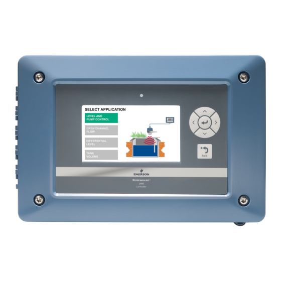
- Page 29 May 2023 Quick Start Guide 3. From the Select application menu, select appropriate application: Option Application Level and pump control Open channel flow Differential level (3490C only) Tank volume 4. Follow the on-screen instructions to configure the controller according to your application. Quick Start Guide...
-
Page 30: Web Interface
Quick Start Guide May 2023 8 Web interface The Rosemount 3490 has a web-based graphical user interface that provides a number of useful service functions, such as: • Firmware upgrade • Log file download to PC Figure 8-1: Web Interface Menus... - Page 31 May 2023 Quick Start Guide Quick Start Guide...
- Page 32 2023 Emerson. All rights reserved. Emerson Terms and Conditions of Sale are available upon request. The Emerson logo is a trademark and service mark of Emerson Electric Co. Rosemount is a mark of one of the Emerson family of companies. All other marks are the property of their respective owners.