Table of Contents
Advertisement
Quick Links
INSTALLER: Leave this manual with party responsible for use and operation.
OWNER: Retain this manual for future reference.
NOTICE:
DO NOT discard this manual!
Model(s):
WOODBURNING FIREPLACE
Outdoor Lifestyles by Hearth & Home Technologies • ODCTGWD Installers Manual • 4108-901 Rev C • 05/23
Installation Manual
Installation and Fireplace Setup
WARNING: If the information in these
instructions is not followed exactly, a fire
or explosion may result causing property
damage, personal injury, or death.
• DO NOT store or use gasoline or other flam-
mable vapors and liquids in the vicinity of this
or any other appliance.
• DO NOT overfire. Overfiring will void your
warranty.
• Comply with all minimum clearances to com-
bustibles as specified. Failure to comply may
cause house fire.
WARNING
HOT SURFACES!
Glass and other surfaces are hot during
operation AND cool down.
Hot glass will cause burns.
• DO NOT touch glass until it is cooled
• NEVER allow children to touch glass
• Keep children away
• CAREFULLY SUPERVISE children in same room as
fireplace.
• Alert children and adults to hazards of high temperatures.
High temperatures may ignite clothing or other flammable
materials.
• Keep clothing, furniture, draperies and other flammable
materials away.
WARNING
Fire Risk.
For use with solid wood fuel only.
Other fuels may overfire and generate
poisonous gases (i.e. carbon monoxide).
1
Advertisement
Table of Contents

Related Manuals for Hearth and Home Technologies outdoor lifestyle ODCTGWD-36


Summary of Contents for Hearth and Home Technologies outdoor lifestyle ODCTGWD-36
- Page 1 Installation Manual Installation and Fireplace Setup INSTALLER: Leave this manual with party responsible for use and operation. OWNER: Retain this manual for future reference. NOTICE: DO NOT discard this manual! WARNING: If the information in these instructions is not followed exactly, a fire or explosion may result causing property damage, personal injury, or death.
-
Page 2: Table Of Contents
Safety Alert Key: • DANGER! Indicates a hazardous situation which, if not avoided will result in death or serious injury. • WARNING! Indicates a hazardous situation which, if not avoided could result in death or serious injury. • CAUTION! Indicates a hazardous situation which, if not avoided, could result in minor or moderate injury. •... - Page 3 ATTENTION INSTALLER: Follow this Standard Work Checklist This standard work checklist is to be used by the installer in conjuction with, not instead of, the instructions contained in this installation manual. Customer: Date Installed: Lot/Address Location of Fireplace: Installer: Model (circle one): Dealer/Distributor Phone # ODCTGWD-36, ODCTGWD-36H Serial #:...
-
Page 4: Product Specific & Important Safety Information
Product Specific & Important Safety Information B. Non-Combustible Materials A. Fireplace Certification • Materials which will not ignite and burn, composed of This fireplace system has been tested and listed in accor- any combination of the following: dance with UL 127 and ULC-S610 standards by Under- writers Laboratories Inc. -
Page 5: Getting Started
Getting Started A. Typical Fireplace System Additional lateral support for chimney above roof (or enclosed Termination cap in chase) if needed Storm Collar Non-combustible roof flashing maintains minimum clearance Chimney penetrates roof around chimney preferably without affecting roof rafters Support straps on rafter support Offset &... -
Page 6: Design And Installation Considerations
B. Design and Installation Considerations Consideration should be given to these factors before deciding on a location. NOTICE: Check building codes prior to installation. NOTICE: In addition to these framing dimensions, also reference the following section: • Installation MUST comply with local, regional, state and •... -
Page 7: Locating Fireplace & Chimney
2. Locating Fireplace & Chimney Location of the fireplace and chimney will affect perfor- mance. • Install the outside air kit with the intake facing prevailing • Install within the warm airspace enclosed by the building winds during the heating season. envelope. -
Page 8: Tools And Supplies Needed
C. Tools and Supplies Needed E. Fireplace System Requirements Before beginning the installation be sure the following The Outdoor Lifestyles fireplace system requirements tools and building supplies are available: consist of the following: Reciprocating saw Framing material • Fireplace Refractory (included with fireplace) Pliers Non-combustible sealant Firescreen (included with fireplace) -
Page 9: Framing And Clearances
Framing and Clearances A. Fireplace Dimensions ODCTGWD-36/36H 28-5/8 in. (727 mm) 14-3/8 in. (365 mm) 9-1/2 in. 27-1/2 in. (241 mm) (699 mm) 44-1/2 in. (1130 mm) Outside Air 55-1/2 in. (1410 mm) (effective height) 59-1/4 in. 49-1/8 in. (1505 mm) Gas Knockout Knockout (1248 mm) -
Page 10: Clearances
B. Clearances Minimum Clearances to Combustibles WARNING! Risk of Fire! WITHIN ENCLOSURE AREA Fireplace to backwall (36/36H) 1 in. (25 mm) You must comply with all minimum air space clearances to combustibles as specified in Figure 3.2. DO NOT pack Fireplace to backwall (42/42H) 1 1/2 in. (38 mm) required air spaces with insulation or other materials. -
Page 11: Construct The Chase
C. Construct the Chase Round Termination Cap A chase is a vertical boxlike structure built to enclose the fireplace and/or its vent system. Vertical chimneys that Storm Collar run on the outside of a building must be installed inside a Metal Chase Top chase. -
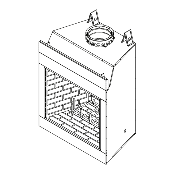
Page 12: Unpack The Fireplace (36/36H Only)
D. Unpack the Fireplace (36/36H only) • 36/36H is shipped with refractory in place. • Remove packaging. • Remove shipping brackets as shown in Figure 3.12. Replace the screws removed from the fireplace. • Remove 36/36H from pallet and set aside. •... -
Page 13: Frame The Fireplace
F. Frame the Fireplace WARNING! Risk of Fire! Comply with all minimum clear- ances specified. NOTICE: Hearth extension design must be determined • 36/36H - A minimum 1 in. (25 mm) air clearance must before installation of fireplace. be maintained at the back and sides of the fireplace assembly. - Page 14 This can be constructed of metal, adhesive polymer membrane (such as ice and water shield) or other Note: suitable materials. A means of drainage out of the pan • Illustrations and photos reflect typical installations such as tubes or weep holes should be provided. A slope and are FOR DESIGN PURPOSES ONLY.
-
Page 15: Secure And Level The Fireplace
G. Secure and Level the Fireplace This fireplace may be placed on either a combustible or noncombustible continuous flat surface. Shipping brack- ets can be used to anchor the fireplace. Slide the fireplace into position. Be sure to provide the minimum 1 in. -
Page 16: Outside Air Kit
I. Outside Air Kit CAUTION! Risk of Cuts/Abrasions. Wear protective gloves and safety glasses during installation. Sheet metal An outside air kit must be used for combustion. Hearth & edges are sharp. Home Technologies recommends you utilize the shortest duct run to optimize the performance of the outside air kit and install a P-Trap (see Figure 3.20). -
Page 17: Chimney And Termination Requirements
Chimney and Termination Requirements NOTICE: A maximum of two pairs of offsets and returns A. Chimney Requirements may be used. Vertical distances are measured from the base of the fireplace as shown in Figure 4.1. WARNING! Risk of Fire! You must maintain 2 in. (51 mm) air space clearance to insulation and other combustible Table 4.1 Chimney Requirements materials around the chimney system. -
Page 18: Offsets/Returns
B. Offsets/Returns • Use an offset/return to bypass overhead obstructions. • An offset and return can be used as a single entity or separated by chimney section(s). WARNING! Risk of Fire! DO NOT use offset/returns greater than 30°. Chimney draft will be restricted and could cause overheating and fire. Secure offsets with screws ( not to exceed 1/2” / 13 mm in length) Secure returns with strapping. Straight chimney sections may be secured with screws. Keep chimney sections from separating or twisting. •... -
Page 19: Termination Requirements
C. Termination Requirements • Install a cap approved and listed for this fireplace system. • Locate cap where it will not become plugged by snow or other materials. • Locate cap away from trees or other structures. • The bottom of the termination cap must be at least 3 ft (.91 m) above the roof AND at least 2 ft (.61 m) above any portion of roof within 10 ft (3.05 m). -
Page 20: Chimney Installation
Chimney Installation A. Typical Chimney System NOTICE: Chimney performance may vary. • Trees, buildings, roof lines and wind conditions affect performance. • Chimney height may need adjustment if smoking or overdraft occurs. Termination Cap Chimney must extend beyond combustible roof structure Additional support for Maintain minimum tall chimneys height of chimney above roof Storm Collar... -
Page 21: Assemble Chimney Sections
B. Assemble Chimney Sections C. Install Chimney Air Kit Use only those components described in this manual. • Required in Canada. • Follow instructions included with accessory. Substitute or damaged chimney components could impair safe operation and cause overheating and fire. Attach either a straight chimney section or an offset to the top of the fireplace (depending on your installation requirement). -
Page 22: Secure Offset/Return
D. Secure Offset/Return ROOM ABOVE (non-insulated ceiling) When offsets and returns are joined to straight pipe sec- tions, they must be locked into position with the screws (outer only). To prevent gravity from pulling the chimney sections apart, the returns and the chimney stabilizers have hanger straps for securing these parts to joists or rafters. -
Page 23: Install Attic Insulation Shield
F. Install Attic Insulation Shield WARNING! Risk of Fire! You MUST install an attic insu- lation shield when there is any possibility of insulation or other combustible material coming into contact with the Pre-bend the tabs to chimney. rest against pipe to prevent insulation DO NOT pack insulation between the chimney and the •... -
Page 24: Roof Penetration
G. Roof Penetration • Refer to Figure 5.8. • Plumb from roof to center of chimney. • Drive a nail up through roof to mark center of pipe. • Measure to either side of nail and mark the 17 in. x 17 in. (432 mm x 432 mm) opening required. -
Page 25: Termination Cap Requirements
I. Termination Cap Requirements • Install a cap approved and listed for this fireplace system. • Locate cap where it will not become plugged by snow or other materials. Assemble Termination storm collar • Locate cap away from trees or other structures. around extended •... - Page 26 Assemble storm collar Termination around extended Place waterproof sealer Cap (not shown) termination cap under each flange of the pipe termination cap and on CT-11A-B once cap is top of each screw to installed. help prevent leaks. Remove 2 screws Termination Cap Do NOT block from front &...
-
Page 27: Shrouds
Shrouds 1. Open Top Shroud WARNING! Risk of Fire! Shrouds must be constructed as specified. Improper construction may overheat TR11/TR11T TV (top vented) caps do not require radia- chase top. tion shield. Shrouds may be field constructed where permitted by regional building codes. Min. NOTICE: Some regional codes require an agency-Listed Radiation Top Dim. -
Page 28: Mailbox Style Shroud
2. Mailbox Style Shroud Radiation shield required Minimum Opening Height 3 in. (76 mm) Min. Opening Height Min. Height above bottom of TR11/11T TR11/11T TV termination Min. Base Dims. Min, Base Dim 34 x 34 28 x 30 Radiation 864 x 864 711 x 762 Min. -
Page 29: Finishing
Finishing A. Finishing Material Refer to Section 1 for combustible/non-combustible mate- rials. Refer to Figure 7.1 for noncombustible zone. These metal surfaces may be covered with non-combustible material. Non-combustible WARNING! Risk of Fire! You must maintain clearances. sealant around edge •... -
Page 30: Hearth Extension, Building And Finishing
B. Hearth Extension, Building and Fin- WARNING! Risk of Fire! ishing • Maintain clearances. • Use only non-combustible material below standoffs, material WARNING! Risk of Fire! High temperatures, sparks, such as cement board is acceptable. embers or other burning material falling from the fire- • Framing or finishing material used on the front of the fireplace place may ignite flooring or concealed combustible closer than the minimums listed, must be constructed entirely surfaces. -
Page 31: Fireplace Installed Flush On The Floor And Hearth Extension Raised To Bottom Of Firebox Opening
1. Fireplace Installed Flush on the Floor and Note: The bottom of the fireplace Hearth Extension Raised to Bottom of Firebox opening is 7-5/8 in. (194 mm) Opening above the bottom of the Non-combustible flooring a minimum of 20 in. (508 fireplace. -
Page 32: Raised Hearth Extension And Raised Fireplace
2. Raised Hearth Extension and Raised Fire- place Non-combustible flooring a minimum of 20 in. (508 mm) in front of and 12 in. (305 mm) to each side of the fuel opening is required. The hearth framing must be constructed of non-com- bustible materials (such as metal framing or equivalent material) and placed on HX4, or equivalent material. -
Page 33: Fireplace Opening And Hearth Extension Flush With The Floor
C. Non-Combustible Sealant Material 3. Fireplace Opening and Hearth Extension Flush with the Floor After completing the framing and applying the facing materials over the framing, a bead of non-combustible Non-combustible flooring a minimum of 20 in. (508 mm) sealant must be used to close off any gaps at the top in front of and 12 in. -
Page 34: Sidewalls/Surrounds
D. Sidewalls/Surrounds • Locate adjacent combustible sidewalls a minimum of 24 in. (610 mm) from fireplace opening. • Mantle leg, surround, stub wall, whether combustible or non-combustible, may be constructed as shown in Figure 7.11. Grid represents inch scale. 4 in. BRICK [102 mm] FLUSH... -
Page 35: Mantel And Wall Projections
E. Mantel and Wall Projections The combustible mantel may have a maximum depth of 12 in. (305mm). Positioned 12 in. (305mm) above the open- ing. Combustible trim pieces that project no more than 1-1/2 in. (38 mm) from the face of the fireplace can be placed no closer than 6 in. -
Page 36: Fireplace Setup
Fireplace Setup A. Gas Log/Lighter Provision B. Wood Burning Inserts WARNING! Risk of Fire! Improper installation of wood in- WARNING! Fire and/or Asphyxiation Risk! Use with serts may cause fireplace or chimney system to overheat. solid wood fuel or decorative gas appliance only. Gas fire generates fumes. If a wood burning insert is being installed in this fireplace, •... -
Page 37: Install The Refractory (42/42H Only)
C. Install the Refractory (42/42H only) Note: To ensure proper installation, gas knockouts in the side refractory should be positioned towards back of fireplace. See We recommend two installers for hearth stone and refrac- Figure 8.5. tory installation! Note: Before installing refractories and hearth stone, be sure all back edges of each piece are smooth to ensure proper fit. -
Page 38: Reference Materials
Reference Materials 14 in. A. Chimney Components 14 in. (356 mm) (356 mm) Catalog # Description 5-1/4 in. CAK5A CAK5A Chimney Air Kit (133 mm) 4 in. (102 mm) ID4/ID6 Insulated Duct/Outside Air 13 in. UD4/UD6 Uninsulated Duct/Outside Air (330 mm) SLA10 11-10 in. - Page 39 Inside Diameter SL1100 11 in. (279 mm) SL400 10 in. (254 mm) 17 in. (432 mm) Outside 21 in. Diameter (533 mm) Catalog # 13 in. (330 mm) FS538 0-deg. 17 in. 432 mm FS540 30-deg. 26 in. 660 mm SL1130/SL430 Offset/Return 15-1/4 in.
- Page 40 TCT1175 - Terra Cotta Cap TR11T - Round Telescoping Termination Cap TR-TVK - Top Vent Kit ST1175 - Square Termination Cap DTS134/DTS146 DTO134/DTO146 Decorative Caps DTO134 DTO146 15-3/4 in. 22.7 1168 (400 mm) DTS134 21.18 DTS146 TR11/TR444 - Round Termination Cap 21.18 1168 Outdoor Lifestyles by Hearth &...
-
Page 41: Optional Components
B. Optional Components 52 in. (1321 mm) 16 in. (406 mm) HX3 Hearth Extension 1/2 in. (13 mm) LDS33/LDS46 Decorative Shroud ID4 Insulated Duct 4 in. (102 mm) i.d. Catalog # LDS33 42 in. LDS46 1219 1829 (1067 mm) ID6 Insulated Duct 6 in. (152 mm) i.d. LDSCPM - Corner Post Kit (for custom sizes) UD4/6 Uninsulated Duct 6 in.