Advertisement
Quick Links
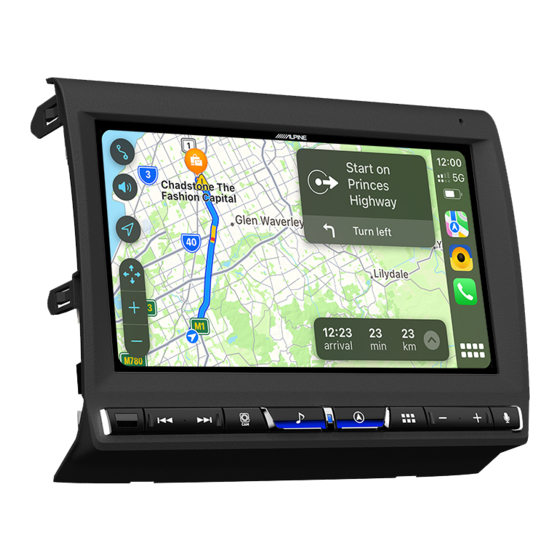
Alpine i905 LC70
Infotainment System
Installation Guide
Toyota
LC70
2010 >
This install manual will give you a clear understanding about the installation of this kit.
To ensure correct installation, please read this manual carefully before starting the
installation.
Advertisement

Related Manuals for Alpine i905


Summary of Contents for Alpine i905
- Page 1 Alpine i905 LC70 Infotainment System Installation Guide Toyota LC70 2010 > This install manual will give you a clear understanding about the installation of this kit. To ensure correct installation, please read this manual carefully before starting the installation.
- Page 3 WARNING Before installing or connecting the unit, please read the following thoroughly for proper use. WARNING CAUTION MAKE THE CORRECT CONNECTIONS. USE SPECIFIED ACCESSORY PARTS AND INSTALL THEM SECURELY. Failure to make the proper connections may result in fire or product damage. Be sure to use only the specified accessory parts.
-
Page 4: Tools & Hardware
Tools & Hardware Trim Removal Tool 10mm Socket and Ratchet PH2 Phillips-Head Screwdriver Rotary Cutting Tool Soldering Iron... - Page 5 Parts Alpine LC70 Fascia Mounting Brackets, LHS and RHS Wiring Harness i905 Head Unit Black Box i905 Screen Key Harness...
- Page 6 Parts 6x Head Unit Bracket Screws DAB+ Antenna GPS Antenna Hazard Key Assembly 4x i905 Screen Screws 4x Fascia Screws 40x12z...
- Page 7 Parts i905 Keys 2x Key Screws 4G x 3/8 PAN Microphone LC70 i905 Screen Bracket...
- Page 8 Disconnection of Battery WARNING It is recommended to disconnect the cable from the negative battery terminal before proceeding with the installation.
- Page 9 Factory Head Unit Removal Use the trim removal tool to dislodge the bottom fascia clips through the recesses in the fascia. Pull the fascia outwards to disengage the mounting clips. Carefully unplug the two connectors on the rear of the fascia and set aside.
- Page 10 Unscrew the 4 head unit bracket bolts using a 10mm socket and remove the head unit from the dashboard. Retain these screws to mount the Alpine unit. Using the 6 head unit screws provided, fasten the left and right side brackets to the...
- Page 11 Trim Dashboard Use a cutting tool to carefully trim the dash in the illustrated location on both the left and right sides of the head unit cavity to allow clearance for the 9” LCD display to be fitted. Use a cutting tool to carefully trim the dash in the illustrated location on both the left and right sides of the head unit cavity to allow clearance for the 9”...
- Page 12 GPS and DAB+ Antenna Installation Route the GPS wire behind the dashboard, place the GPS antenna on the metal backplate and mount the antenna faced upwards and as close to the top of the dashboard as possible. Remove the passenger side grab handle and A-pillar trim, route the DAB antenna wire and mount the antenna to the windscreen.
- Page 13 HAZARD OUTPUT WIRE LIGHT GREEN The supplied Alpine hazard switch must be soldered to the factory hazard switch wiring as shown in the above diagram. The red wire on the hazard switch is not used. Route the hazard switch connector down through the HVAC blank and connect it to the supplied Alpine hazard switch.
- Page 14 AMPLIFIER WHEN ADDING EXTERNAL AMPLIFIER REAR OUT DISPLAY POWER HARNESS TO LCD SCREEN EXTERNAL KEYS TO KEYS (12 PIN) ALPINE TO TOYOTA CONNECTORS (PEF-10-WHA) TO TOYOTA CONNECTORS Connect all supplied wiring to the vehicle connectors and the Alpine head unit black box.
- Page 15 Ensure that the display cable, display power harness and external key harnesses are routed in front of the head unit black box. 4x i905 LCD SCREWS (SUPPLIED) 2x 4G 3/8 PAN SCREWS (SUPPLIED) Attach the i905 screen and keys to the LC70 screen bracket with the screws provided.
- Page 16 Assemble Fascia With the fascia placed face down, fit the microphone into the fascia. Place the LC70 bracket with screen and keys into position. Ensure that the microphone cable remains clear of the bracket assembly. 4x 40 x 12z SCREWS (SUPPLIED) CAUTION Be extremely careful with...
- Page 17 Route the microphone wire across the back of the bracket as illustrated above. Flip the fascia assembly over and ensure that the keys, screen and Alpine logo are positioned centrally, perfectly horizontally and have consistent gaps all around. If any adjustment is needed, loosen the screws on the rear of the bracket and reposition accordingly.
-
Page 18: Installation Complete
Installation Complete Installation is complete. - Page 19 Notes...
- Page 20 ALPINE ELECTRONICS OF AUSTRALIA PTY. LIMITED 161-165 Princes Highway Hallam, Victoria 3803 Australia http://www.alpine.com.au...