Table of Contents
Advertisement
Safe Operation Practices • Set-Up • Operation • Maintenance • Service • Troubleshooting • Warranty
O
'
M
peratOr
s
anual
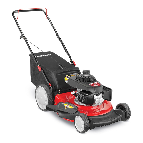
Push Mower — Model TB130
WARNING
READ AND FOLLOW ALL SAFETY RULES AND INSTRUCTIONS IN THIS MANUAL
BEFORE ATTEMPTING TO OPERATE THIS MACHINE.
FAILURE TO COMPLY WITH THESE INSTRUCTIONS MAY RESULT IN PERSONAL INJURY.
TROY-BILT LLC, P.O. BOX 361131 CLEVELAND, OHIO 44136-0019
Printed In USA
Form No. 769-08794
(January 16, 2013)
Advertisement
Table of Contents

Related Manuals for Troy-Bilt TB130


Summary of Contents for Troy-Bilt TB130
- Page 1 READ AND FOLLOW ALL SAFETY RULES AND INSTRUCTIONS IN THIS MANUAL BEFORE ATTEMPTING TO OPERATE THIS MACHINE. FAILURE TO COMPLY WITH THESE INSTRUCTIONS MAY RESULT IN PERSONAL INJURY. TROY-BILT LLC, P.O. BOX 361131 CLEVELAND, OHIO 44136-0019 Printed In USA Form No. 769-08794...
-
Page 2: Table Of Contents
Visit us on the web at www.troybilt.com See How-to Maintenance and Parts Installation Videos at www.troybilt.com/tutorials ◊ Call a Customer Support Representative at (800) 828-5500 or (330) 558-7220 ◊ Write to Troy-Bilt LLC • P.O. Box 361131 • Cleveland, OH • 44136-0019... -
Page 3: Safe Operation Practices
Important Safe Operation Practices WARNING: This symbol points out important safety instructions which, if not followed, could endanger the personal safety and/or property of yourself and others. Read and follow all instructions in this manual before attempting to operate this machine. Failure to comply with these instructions may result in personal injury. - Page 4 A missing or damaged discharge cover can cause blade When starting engine, pull cord slowly until resistance contact or thrown object injuries. is felt, then pull rapidly. Rapid retraction of starter cord (kickback) will pull hand and arm toward engine faster than Many injuries occur as a result of the mower being pulled you can let go.
- Page 5 Service Check the blade and engine mounting bolts at frequent intervals for proper tightness. Also, visually inspect blade Safe Handling Of Gasoline: for damage (e.g., bent, cracked, worn) Replace blade with the original equipment manufacture’s (O.E.M.) blade only, To avoid personal injury or property damage use extreme listed in this manual.
- Page 6 Notice Regarding Emissions Spark Arrestor Engines which are certified to comply with California and federal WARNING: This machine is equipped with an EPA emission regulations for SORE (Small Off Road Equipment) internal combustion engine and should not be used are certified to operate on regular unleaded gasoline, and on or near any unimproved forest-covered, brush may include the following emission control systems: Engine covered or grass-covered land unless the engine’s...
- Page 7 Safety Symbols This page depicts and describes safety symbols that may appear on this product. Read, understand, and follow all instructions on the machine before attempting to assemble and operate. Symbol Description READ THE OPERATOR’S MANUAL(S) Read, understand, and follow all instructions in the manual(s) before attempting to assemble and operate DANGER —...
- Page 8 2 — i ection mportant peration racticeS...
-
Page 9: Assembly & Set-Up
Assembly & Set-Up Contents of Carton • One Lawn Mower • One Grass Catcher • One Bottle of Oil • One Lawn Mower Operator’s Manual • One Engine Operator’s Manual • One Side Discharge Chute NOTE: Please be aware that this Operator’s Manual covers both While stabilizing mower so it doesn’t move, pivot the low and high wheel models of this mower. - Page 10 Remove the T-bolts from the handle brackets as shown in Figure 3-3. Figure 3-5 The rope guide is attached to the right side of the upper handle. Loosen the wing knob which secures the rope Figure 3-3 guide. See Figure 3-6. Follow the steps below to complete handle assembly: Pull upward on the handle until holes in lower handle (shown in Figure 3-3 deck cutaway) line up...
- Page 11 Side Discharge Chute Slip plastic channel of grass bag over hooks on the frame. See Figure 3-7. Your mower is shipped as a mulcher. To convert to side discharge, make sure grass catcher is off of the unit and rear discharge door is closed.
- Page 12 Adjustments Handle Pitch For convenience of operation, you may adjust the pitch of the Cutting Height handle as follows: There is a cutting height adjustment lever located above the Remove wing nuts and carriage bolts from handle. See front and rear right wheel. Figure 3-11.
-
Page 13: Controls & Features
Controls and Features Blade Control Recoil Starter Grass Catcher Cutting Height Adjustment Lever Side Discharge Chute Cutting Height Adjustment Lever Mulch Plug Blade Control Mulch Plug The blade control is attached to the upper handle of the mower. The mulch plug is used for mulching purposes. Instead of Depress and squeeze it against the upper handle to operate the collecting the grass clippings in a grass catcher or using the unit. -
Page 14: Operation
Operation Starting Engine WARNING: Be sure no one other than the operator is standing near the lawn mower while starting engine or operating mower. Never run engine indoors or in enclosed, poorly ventilated areas. Engine exhaust contains carbon monoxide, an odorless and deadly gas. - Page 15 Using as Mulcher Lift discharge door and pull grass bag up and away from the mower to remove the bag. Dispose of the grass For mulching grass, remove the grass catcher and allow the rear clippings and reinstall the bag when complete. discharge door to close the rear opening of mower.
-
Page 16: Maintenance & Adjustment
Maintenance & Adjustments Maintenance Deck Care Clean underside of the mower deck after each use to prevent General Recommendations build-up of grass clippings or other debris. Follow steps below • Always observe safety rules when performing any for this job. maintenance. -
Page 17: Service
Service Blade Care Place blade bell support on the blade. Align notches on the blade bell support with small holes in blade. WARNING: When removing the cutting blade for Replace hex bolt and tighten hex bolt to torque: 450 in. lbs. sharpening or replacement, protect your hands with min., 600 in. -
Page 18: Troubleshooting
Troubleshooting Problem Cause Remedy Engine Fails to start 1. Blade control disengaged. 1. Engage blade control. 2. Spark plug boot disconnected. 2. Connect wire to spark boot. 3. Fuel tank empty or stale fuel. 3. Fill tank with clean, fresh gasoline. 4. -
Page 19: Replacement Parts
Replacement Parts Component Part Number and Description 98079-55846 Spark Plug (NGK BPR5ES) 16952-ZA8-800 Fuel Filter † 17211-ZL8-023 Air Cleaner Element 17620-Z0J-800 Fuel Cap 634-04607 Wheel (Front) 634-04626 Wheel (Rear) 731-07131 Discharge Chute 942-0741A Mulching Blade 942-0741-X Xtreme Mulching Blade 964-04117A Grass Bag †... -
Page 20: Attachments & Accessories
Attachments & Accessories Component Model Number and Description 490-850-0005 Blade Removal Tool — Holds blade in place for faster, safer removal. SPW-134 Spark Plug Wrench — Duel ended wrench to serve multiple uses. Fits ¾” or 13⁄16” hex plug. 490-850-0008 Oil Siphon —... - Page 21 Component Model Number and Description 22216 STA-BIL® fuel Stabilizer, 32 oz — Treats 80 gallons of fuel. Keeps stored fuel fresh for quick, easy starts. Prevents corrosion from moisture and ethanol-induced attraction. Prevents gum and varnish. 490-290-0012 Mower Cover — Protects your mower against sun, rain and dust damage.
-
Page 24: Warranty
Warranty Conditions — Australia (Not applicable to other Regions) The benefits given to you under this warranty are in addition to other rights and remedies that you have under Australian law in relation to the goods. MTD Products Australia Pty Ltd warrants that this machine is free from defects in material and workmanship. This warranty is limited to repairing or replacing any part which appears upon inspection by MTD Products Australia Pty Ltd or its agent to be defective in material or workmanship.