Table of Contents
Advertisement
Safe Operation Practices • Set-Up • Operation • Maintenance • Service • Troubleshooting • Warranty
O
'
M
peratOr
s
anual
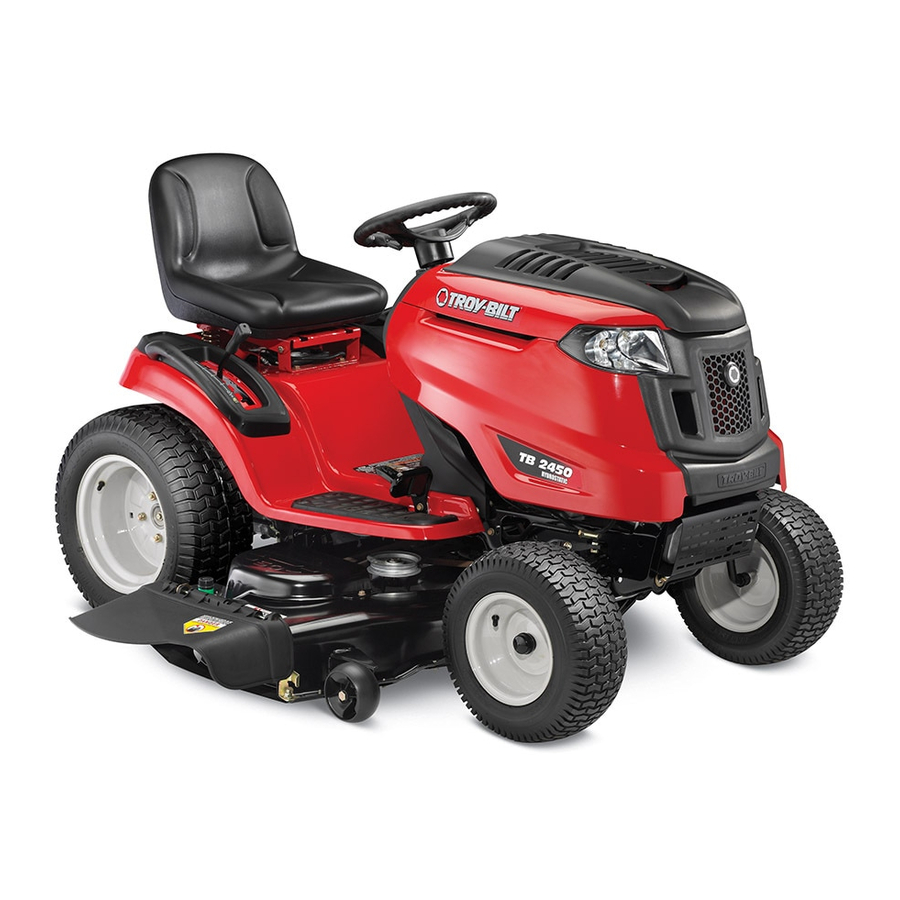
Hydrostatic Lawn Tractor — TB2450
WARNING
READ AND FOLLOW ALL SAFETY RULES AND INSTRUCTIONS IN THIS MANUAL
BEFORE ATTEMPTING TO OPERATE THIS MACHINE.
FAILURE TO COMPLY WITH THESE INSTRUCTIONS MAY RESULT IN PERSONAL INJURY.
TROY-BILT LLC, P.O. BOX 361131 CLEVELAND, OHIO 44136-0019
Printed In USA
Form No. 769-06611
(November 11, 2010)
Advertisement
Table of Contents

Related Manuals for Troy-Bilt TB2450


Summary of Contents for Troy-Bilt TB2450
- Page 1 READ AND FOLLOW ALL SAFETY RULES AND INSTRUCTIONS IN THIS MANUAL BEFORE ATTEMPTING TO OPERATE THIS MACHINE. FAILURE TO COMPLY WITH THESE INSTRUCTIONS MAY RESULT IN PERSONAL INJURY. TROY-BILT LLC, P.O. BOX 361131 CLEVELAND, OHIO 44136-0019 Printed In USA Form No. 769-06611...
-
Page 2: Table Of Contents
Call a Customer Support Representative at (800) 828-5500 or (330) 558-7220 ◊ Write to Troy-Bilt LLC • P.O. Box 361131 • Cleveland, OH • 44136-0019 If you have any problems or questions concerning the machine, phone a authorized Troy-Bilt service dealer or contact us directly. -
Page 3: Safe Operation Practices
Important Safe Operation Practices WARNING! This symbol points out important safety instructions which, if not followed, could endanger the personal safety and/or property of yourself and others. Read and follow all instructions in this manual before attempting to operate this machine. Failure to comply with these instructions may result in personal injury. - Page 4 A missing or damaged discharge cover can cause blade contact or thrown object injuries. Stop the blade(s) when crossing gravel drives, walks, or roads and while not cutting grass. Watch for traffic when operating near or crossing roadways. This machine is not intended for use on any public roadway.
- Page 5 Children Tragic accidents can occur if the operator is not alert to the presence of children. Children are often attracted to the machine and the mowing activity. They do not understand the dangers. Never assume that children will remain where you last saw them.
-
Page 6: Spark Arrestor
Periodically check to make sure the blades come to complete stop within approximately (5) five seconds after operating the blade disengagement control. If the blades do not stop within the this time frame, your machine should be serviced professionally by an authorized MTD Service Dealer. -
Page 7: Safety Symbols
Safety Symbols This page depicts and describes safety symbols that may appear on this product. Read, understand, and follow all instructions on the machine before attempting to assemble and operate. Symbol READ THE OPERATOR’S MANUAL(S) Read, understand, and follow all instructions in the manual(s) before attempting to assemble and operate DANGER—... - Page 8 2 — i ectiOn MpOrtant peratiOn ractices...
-
Page 9: Assembly & Set-Up
Assembly & Set-Up Contents of Crate • One Lawn Tractor • One Lawn Tractor Operator’s Manual Tractor Set-Up Moving The Tractor Manually Your tractor’s transmission is equipped with a hydrostatic relief valve for occasions when it is necessary to move the tractor manually. - Page 10 Connecting the Battery Cables CALIFORNIA PROPOSITION 65 WARNING! Battery posts, terminals, and related accessories contain lead and lead compounds, chemicals known to the State of California to cause cancer and reproductive harm. Wash hands after handling. CAUTION: When attaching battery cables, always connect the POSITIVE (Red) wire to its terminal first, followed by the NEGATIVE (Black) wire.
- Page 11 Adjusting the Seat To adjust the position of the seat, pull up and hold the seat adjustment lever. Slide the seat forward or rearward to the desired position; then release the adjustment lever. Make sure seat is locked into position before operating the tractor. See Fig. 3-5.
-
Page 12: Controls
Controls and Features Systems Indicator Monitor Brake Pedal Cup Holder Lawn Tractor controls and features are illustrated in Fig 4-1 and described on the following pages. WARNING! Read and follow all safety rules and instructions in this manual, including the entire Operation section, before attempting to operate this machine. - Page 13 Deck Lift Lever Found on your tractor’s right fender, the deck lift lever is used to change the height of the cutting deck. To use, move the lever to the left, then place in the notch best suited for your application. Ignition Switch Module WARNING! Never...
- Page 14 Fuel Level Indicator The Fuel Level Indicator is located on the left side of the tractor’s dash and indicates the amount of fuel in the gas tank. PTO / Blade Engage Knob Activating the PTO engages power to the cutting deck or other (separately available) attachments.
-
Page 15: Operation
Operation TO AVOID SERIOUS INJURY OR DEATH • GO UP AND DOWN SLOPES, NOT ACROSS. • AVOID SUDDEN TURNS. • DO NOT OPERATE THE UNIT WHERE IT COULD SLIP OR TIP. • IF MACHINE STOPS GOING UPHILL, STOP BLADE(S) AND BACK DOWNHILL SLOWLY. •... -
Page 16: Driving The Tractor
Driving The Tractor WARNING! Avoid sudden starts, excessive speed and sudden stops. Lightly press the brake pedal to release the parking brake. Move the throttle lever into the FAST (rabbit) position. To travel FORWARD, slowly press the upper portion of the drive pedal forward until the desired speed is achieved. -
Page 17: Engaging The Parking Brake
Driving On Slopes Refer to the SLOPE GAUGE on page 8 to help determine slopes where you may operate the tractor safely. WARNING! Do not mow on inclines with a slope in excess of 15 degrees (a rise of approximately 2-1⁄2 feet every 10 feet). - Page 18 Engaging the PTO Engaging the PTO transfers power to the cutting deck or other (separately available) attachments. To engage the PTO: Move the throttle control lever to the FAST (rabbit) position. Pull the PTO/Blade Engage knob outward into the engaged (ON) position.
-
Page 19: Maintenance & Adjustment
NOTE: Maintenance, repair, or replacement of the emission control devices and systems which are being done at owner’s expense may be performed by any engine repair establishment or individual. Warranty repairs must be performed by a Troy-bilt Dealer. Before Every... - Page 20 Pop open the protective cap on the end of the oil drain valve to expose the drain port. See Fig 6-1. Figure 6-1 Remove the oil fill cap/ dipstick from the oil fill tube. Push the oil drain hose (packed with this manual) onto the oil drain port.
- Page 21 Attach the hose coupler to the water port on your decks surface. See Fig. 6-2. Figure 6-2 Turn the water on. While sitting in the operator’s position on the tractor, start the engine and place the throttle lever in the FAST (rabbit) position.
- Page 22 (and the hydrostatic relief valve open), the brake is in need of adjustment. See your Troy-bilt dealer to have the brake properly adjusted.
- Page 23 Steering Adjustment If the tractor turns tighter in one direction than the other, or if the ball joints are being replaced due to damage or wear, the steering drag links may need to be adjusted. Adjust the drag links so that equal lengths of each are threaded into the ball joint on the left side and the ball joint on the right side: Remove the hex nut on the top of ball joint.
-
Page 24: Service
Service Cutting Deck Removal To remove the cutting deck, proceed as follows: Place the PTO/Blade Engage knob in the disengaged (OFF) position and engage the parking brake. Lower the deck by moving the deck lift lever into the bottom notch on the right fender. Locate the PTO clutch under the front of your tractor. - Page 25 Pull the deck support pin outward to release the deck from the deck lift arm. See Fig. 7-3. Deck Lift Arm Deck Support Pin Figure 7-3 Repeat the above steps on the tractor’s right side. Move the deck lift lever into the top notch to raise the deck lift arms up and out of the way.
-
Page 26: Cutting Blades
Cutting Blades WARNING! Shut the engine off and remove ignition key before removing the cutting blade(s) for sharpening or replacement. Protect your hands by using heavy gloves when grasping the blade WARNING! Periodically inspect the blade and/or spindle for cracks or damage, especially after you’ve struck a foreign object. - Page 27 Battery CALIFORNIA PROPOSITION 65 WARNING Battery posts, terminals, and related accessories contain lead and lead compounds, chemicals known to the State of California to cause cancer and reproductive harm. Wash hands after handling. CAUTION: If removing the battery, disconnect the NEGATIVE (Black) wire from it’s terminal first, followed by the POSITIVE (Red) wire.
- Page 28 Changing the Deck Belt WARNING! Shut the engine off and remove ignition key before removing the cutting blade(s) for sharpening or replacement. Protect your hands by using heavy gloves when grasping blades and pulleys. WARNING! The V-belts found on your tractor are specially designed to engage and disengage safely.
-
Page 29: Troubleshooting
Troubleshooting Problem Engine fails to start PTO/Blade Engage knob engaged. Parking brake not engaged. Spark plug wire(s) disconnected. Throttle/Choke control lever not in correct starting position. Choke not activated Fuel tank empty, or stale fuel. Blocked fuel line. Faulty spark plug(s). Engine flooded. -
Page 30: Replacement Parts
Replacement Parts Component Contact your Troybilt dealer to order replacement parts or a complete Parts Manual (have your full model number and serial number ready). Parts Manual downloads are also available free of charge at www.troybilt.com. Part Number and Description 759-3336 Spark Plug (Champion RC12YC) KH-32-883-03-S1 Air Filter Element and Pre-Cleaner... - Page 31 Component Contact your Troybilt dealer to order replacement parts or a complete Parts Manual (have your full model number and serial number ready). Parts Manual downloads are also available free of charge at www.troybilt.com. Part Number and Description 734-04155 Deck Wheel (Front) 734-0973 Deck Wheel (Rear) 925-1707D...
-
Page 32: Attachments & Accessories
Attachments & Accessories The following attachments and accessories are compatible for the Troy-bilt TB2450. See your Troy-bilt dealer or the retailer from which you purchased your tractor for information regarding price and availability. CAUTION: Troy-bilt Series TB2450 lawn tractors are NOT designed for use with any type of ground-engaging attachments (e.g. - Page 33 Notes...
- Page 34 FEDERAL and/or CALIFORNIA EMISSION CONTROL WARRANTY STATEMENT MTD Consumer Group Inc, the United States Environmental Protection Agency (EPA), and, for those products certified for sale in the state of California, the California Air Resources Board (CARB) are pleased to explain the emission (evaporative and/or exhaust) control system (ECS) warranty on your outdoor 2006 and later small off-road spark-ignited engine and equipment (outdoor equipment engine) In California, new outdoor equipment engines must be designed, built and equipped to meet the State’s stringent anti-smog standards (in other states, 1997 and later model year equipment must be designed, built, and equipped to meet the U.S.
- Page 35 The repair or replacement of any warranted part otherwise eligible for warranty coverage may be excluded from such warranty coverage if MTD Consumer Group Inc demonstrates that the outdoor equipment engine has been abused, neglected, or improperly maintained, and that such abuse, neglect, or improper mainte- nance was the direct cause of the need for repair or replacement of the part.
- Page 36 MANUFACTURER’S LIMITED WARRANTY FOR The limited warranty set forth below is given by Troy-Bilt LLC with respect to new merchandise purchased and used in the United States and/or its territories and possessions, and by MTD Products Limited with respect to new merchandise purchased and used in Canada and/ or its territories and possessions (either entity respectively, “Troy-...