Simrad NSS9 Evo3S Operator's Manual
Hide thumbs
Also See for NSS9 Evo3S:
- Installation manual (52 pages) ,
- Quick manual (5 pages) ,
- Installation manual (206 pages)
Table of Contents
Advertisement
Quick Links
Advertisement
Table of Contents

Related Manuals for Simrad NSS9 Evo3S


Summary of Contents for Simrad NSS9 Evo3S
- Page 1 NSS evo3S Operator Manual ENGLISH www.simrad-yachting.com...
- Page 3 Documentation, the English language version of the Documentation will be the official version of the Documentation. Trademarks ® Navico is a registered trademark of Navico Holding AS. ® Simrad is used by license from Kongsberg. ® Bluetooth is a registered trademark of Bluetooth SIG, Inc. ® C-MAP is a registered trademark of Navico Holding AS.
- Page 4 Warranty The warranty card is supplied as a separate document. In case of any queries, refer to the brand website of your unit or system: www.simrad-yachting.com Compliance statements Declarations The relevant declaration of conformity is available in the product's section at the following website: www.simrad-yachting.com...
- Page 5 This manual is written for software version 19.3. The manual is continually updated to match new software releases. The latest available manual version can be downloaded from the following website: • www.simrad-yachting.com Translated manuals Available translated versions of this manual can be found on the following website: •...
- Page 6 Viewing the manual on the screen The PDF viewer included in the unit makes it possible to read the manuals and other PDF files on the screen. The manuals can be read from a storage device connected to the unit or copied to the unit’s internal memory.
-
Page 7: Table Of Contents
Contents 13 Introduction Front controls Card reader Home page Application pages 18 Basic operation Turning the system on and off Touchscreen, keyboard and mouse operation Remote controllers System controls dialog Screen capture 20 Customizing your system Customizing the Home page wallpaper Configurable WheelKey Customizing the long press feature Multiple panel pages... - Page 8 46 Navigating About navigating Navigation panels Use menu options Navigating with the autopilot Navigation settings 50 TripIntel About TripIntel Current trip statistics Automatic trip recording Start and stop trip recordings Long-term statistics Estimated fuel range ring Fuel gauge Tide gauge View trip recordings 53 Radar About radar...
- Page 9 Upload sonar logs to C-MAP Genesis Customizing the image Advanced options More options Echosounder settings 80 SideScan About SideScan The SideScan panel Zooming the image Using the cursor on the panel Viewing history Recording SideScan data Setting up the image Advanced options More options Echosounder settings...
- Page 10 ForwardScan installation settings 96 Autopilot Safe operation with the autopilot Selecting active autopilot The autopilot controller Engaging and disengaging the autopilot Autopilot indication Autopilot modes 101 Operating a professional autopilot system 103 Autopilot settings 106 Trolling motor autopilot 106 Safe operation with the autopilot 106 Selecting active autopilot 106 The autopilot controller for trolling motor 107 Engaging and disengaging the autopilot...
- Page 11 131 Internet connection 131 Internet usage 131 Ethernet connection 131 WiFi connection 131 Wireless settings 133 Remote control of the MFD 133 Remote control options 133 Smartphones and tablets 135 Using your phone with the MFD 135 About phone integration 135 Connecting and pairing a phone 135 Phone notifications 136 Phone troubleshooting...
- Page 12 154 Appendix 154 Touchscreen operation 155 Keyboard operation 156 Mouse operation 156 Status bar icon definitions Contents | NSS evo3S Operator Manual...
-
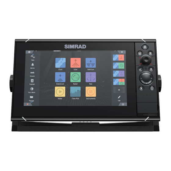
Page 13: Introduction
Introduction Front controls Touch screen Pages/Home • Press to open the Home page for page selection and setup options. WheelKey - user configurable key. Refer to "Configurable WheelKey" on page 20. Default without an autopilot connected to the system: • Short press: toggles between panels on split screen. -
Page 14: Card Reader
Power key • Press and hold to turn the unit ON/OFF. • Press once to display the System Controls dialog. Repeat short presses to toggle through the default dimming levels. Card reader door Card reader A memory card can be used for: •... - Page 15 Settings button Select to access application and feature settings dialogs. These dialogs are used to configure the feature during installation and for making user settings. The settings dialogs are explained toward the end of each application chapter. Toolbar buttons Provide access to options and tools that are not specific to any panel. For toolbar button explanations, refer to "Tools and settings"...
-
Page 16: Application Pages
• A MOB waypoint is created at the vessel’s position • The display switches to a zoomed chart panel, centered on the vessel's position • The system displays navigation information back to the MOB waypoint Multiple MOB waypoints can be created. The vessel continues to show navigation information to the initial MOB waypoint. - Page 17 Menu button Displays the menu of the active panel. Use menu options to customize the image. The panel menu options are further explained later in this manual in each application chapter. Instrument bar The instrument bar displays information from sensors connected to the system. By default, the instrument bar is shown on the panel.
-
Page 18: Basic Operation
To find out which remote controllers can be used, refer to the product web page at: www.simrad-yachting.com Smart devices can also be connected to the unit and remotely control the unit. For information about how to connect smart devices to remotely control the unit, refer to "Remote... -
Page 19: Screen Capture
Brightness You can cycle the preset backlight levels by short presses on the Power key. The display backlighting can also be adjusted from the System Controls dialog. Night mode The night mode can be activated from the System Controls dialog. The night mode option optimizes the color palette for low light conditions. -
Page 20: Customizing Your System
Customizing your system Customizing the Home page wallpaper The Home page's wallpaper can be customized. You can select one of the pictures included with the system, or you can use your own picture in .jpg or .png format. The images can be available on any location that can be seen in the storage browser. When a picture is chosen as the wallpaper, it is automatically copied to the Wallpaper folder. -
Page 21: Customizing Favorite Pages
The shadow cursor on a multiple panel page When using the cursor on a sonar (sonar, DownScan, or SideScan) image on a multiple panel page, the cursor is shadowed on the other sonar (sonar, DownScan, and SideScan), chart and radar panels. Customizing favorite pages Adding new favorite pages Ú... -
Page 22: Adjusting The Split On Multiple Panel Pages
Reset the instrument bar You can reset the instrument bar from the edit menu option to show the predefined default gauges. Fuel economy gauge You can display a fuel economy gauge in the instrument bar on application pages. Select the predefined Fuel activity bar or change a gauge source to the Fuel Economy option found in the Vessel category of the choose data dialog. -
Page 23: Enabling Or Disabling Features
Open the System Controls dialog Select the adjust splits option. The adjustment icon appears on the multiple panel page. Select the adjustment icon and move the split to the desired position Use menu options to save or discard your changes. Enabling or disabling features A compatible device connected to the unit should automatically be identified by the system. -
Page 24: Bridge Control
Bridge Control About Bridge Control The Bridge Control feature allows you to control which pages are shown on several displays at the same time. The feature is used on vessels with multiple displays mounted in the same place to quickly configure what information is displayed. There can be a maximum of four different bridges on your system, and you can have up to four displays grouped into one bridge. - Page 25 Selecting Bridge presets You can display an overview of available bridge presets by opening the Bridge Control option on the home page. When you select one of the preset configurations all devices included in that bridge will switch to the pre-configured pages. Customizing your system | NSS evo3S Operator Manual...
-
Page 26: Charts
Charts The Chart panel North indicator Vessel Chart range scale Grid lines* Range rings* * Optional chart items. Optional chart items can be turned on/off individually from the chart settings dialog. Chart data The system can be delivered with preloaded cartography. For a full selection of supported charts, visit the product web site. -
Page 27: Zooming The Chart
Zooming the chart The chart range scale and range rings interval (when turned on) are shown on the chart panel. You change the scale by zooming the chart in or out. Panning the chart You can move the chart in any direction by: •... -
Page 28: Using The Cursor On The Panel
Ú Note: If you are viewing applicable C-MAP charts on your system, you can select marine objects to display information about services and available multimedia (photos) associated with the location or object. Ú Note: Pop-up information has to be enabled in chart settings to see basic item information. -
Page 29: Creating Routes On The Chart Panel
Creating routes on the chart panel Activate the cursor on the chart panel Select the new route option from the menu Position the first waypoint on the chart panel Continue positioning the remaining routepoints Save the route by selecting the save option in the menu. Find objects on chart panels You can search for other vessels or various chart items from a chart panel. -
Page 30: 3D Charts
Define the four corners of the search area, by entering corner coordinates. The following settings must be defined: • Track width - controls how much space is in between parallel legs (the legs with the longest length). • Number of vessels - controls how many SAR routes are generated. An SAR route is created for each vessel. -
Page 31: Tracks
To return the chart to vessel position use the return to vessel option. Controlling the view angle You can control the view angle by selecting the rotate icon, and then panning the chart panel. • To change the direction you are viewing, pan horizontally •... -
Page 32: Chart Overlay
Chart overlay You can add overlays on the chart panel. When an overlay is selected, the chart menu expands to include basic menu options for the selected overlay. Information about the overlay menu options are described in more detail below or in their separate sections in this manual. - Page 33 C-MAP specific chart options Photo overlay Photo overlay enables you to view satellite photo images of an area as an overlay on the chart. The availability of such photos is limited to certain regions, and cartography versions. You can view photo overlays in either 2D or 3D modes. No Photo overlay Photo overlay, land only Full Photo overlay...
- Page 34 Depth palette Controls the Depth palette used on the map. Navigation Color shades depth areas based on depth range values set by the system. If the depth is within a certain range the system will select the exact color of that range. It colors darker shades of blue in shallower water and whiter in deeper water.
-
Page 35: Navionics Charts
Genesis Layer The Genesis Layer displays high-resolution contours contributed by Genesis users that have passed a quality check. This option toggles the Genesis layer on/off on the chart image. Available only if the C-MAP chart contains Genesis Layer data. Navionics charts Some Navionics features require the most current data from Navionics. - Page 36 No Depth highlight range Depth highlight range: 6 m - 12 m Shallow water highlight This highlights areas of shallow water between 0 and the selected depth (up to 10 meters/30 feet). No shallow water highlighted Shallow water highlight: 0 m - 3 m Safety depth The Navionics charts use different shades of blue to distinguish between shallow and deep water.
- Page 37 Palettes Used for selecting the image's color palette. SCL History Select to display previously recorded data on the chart overlay. SC Density Controls the density of the SonarChart and SonarChart Live contours. Colored seabed areas Used for displaying different depth areas in different shades of blue. Navionics Dynamic tides and current icons Shows tides and currents with a gauge and an arrow instead of the diamond icons used for static tides and current information.
-
Page 38: Chart Settings
Chart details Provides you with different levels of geographical layer information. Easy View Magnifying feature that increases the size of chart items and text. Ú Note: There is no indication on the chart showing that this feature is active. Chart settings The options in the chart settings dialog depends on which chart source is selected in the system. - Page 39 Pop-up information Determines whether basic information for panel items is displayed when you select the item. Grid lines Turns on/off viewing of longitude and latitude grid lines on the panel. Waypoints, Routes, and Tracks Turns on/off displaying of these items on chart panels. Ú...
-
Page 40: Waypoints, Routes, And Tracks
Waypoints, routes, and tracks Waypoints, Routes, and Tracks dialogs These dialogs give access to advanced edit functions and settings for these items. The Plot dialog Press and hold the mark/waypoint key to open the Plot dialog. Select an option to add new or manage existing waypoints, routes or tracks. -
Page 41: Routes
Moving a waypoint A waypoint can be moved from the position if active and if the waypoint is selected in the menu. To move a waypoint to a new position, select the move waypoint menu option and then select the new waypoint location on the image. To save the waypoint at the new position, select the finish moving menu option Edit a waypoint You can edit all information about a waypoint from the edit waypoint dialog. - Page 42 - If you set the new routepoint on a leg, a new point is added between existing routepoints - If you set the new routepoint outside the route, the new routepoint is added after the last point in the route Drag a routepoint to move it to a new position Save the route by selecting the save option in the menu.
-
Page 43: Tracks
Dock-to-dock Autorouting and Easy Routing examples Entire route option used when first and last route points are selected. • First and last routepoint Result after automatic routing Selection option used for autorouting part of a route. • Two routepoints selected Result after automatic routing The edit route dialog You can manage routes and routepoints, and change route properties using the Edit Route... - Page 44 About tracks Tracks are a graphical presentation of the historical path of the vessel. They allow for retracing where your boat has travelled. Example of the Tracks dialog: Automatic tracking From the factory, the system is set to automatically track and draw the vessel's movement on the chart panel.
-
Page 45: Map Embark
Deleting tracks You can delete a track by selecting it in the tracks dialog and then deleting it in the edit track dialog. You can delete all the tracks from the system using the tracks dialog. You can back-up your waypoints, routes and tracks before deleting them, refer to "Maintenance" on page 144. -
Page 46: Navigating
Navigating About navigating The navigation function included in the system allows you to navigate to the cursor position, to a waypoint, or along a predefined route. If autopilot functionality is included in your system, the autopilot can be set to automatically navigate the vessel. -
Page 47: Use Menu Options
If Loran is enabled in the Navigation settings dialog, there are two position panels. This is indicated with arrow symbols on left and right side of the panel. You toggle between the panels by: • selecting the left or right arrow symbols •... - Page 48 The Great circle route is the shortest path between two points. However, if you are to travel along such a route, it would be difficult to steer manually as the heading would constantly be changing (except in the case of due north, south, or along the equator). Rhumb lines are tracks of constant bearing.
- Page 49 Datum This system uses the WGS datum format, which is a standard for use in cartography and satellite navigation (including GPS). You can change the datum format to match other systems. Coordinate system Used to set the geographic coordinate system used on your system. Phantom Loran Enables use of Phantom Loran positioning system.
-
Page 50: Tripintel
TripIntel About TripIntel TripIntel lets you store and recall information on trips. You can use the information to make informed decisions prior to commencing a trip, or when a trip is underway. Current trip statistics The Information tab on the TripIntel page shows current trip statistics: •... -
Page 51: Long-Term Statistics
Long-term statistics Select Long Term Statistics to view seasonal trip information. Adjust total distance Select the Adjust total distance button to change the Total distance. Use this option if you have not recorded a trip or part of a trip that you have taken and want to include the distance in the Total distance statistic. -
Page 52: View Trip Recordings
View trip recordings Recorded trips are listed in the history tab on the TripIntel page. To view detailed trip information select a trip in the list. Change trip recording names Trips are given generic names when they are created. You can change the trip name to a more meaningful one by selecting it on the History list and then select the name in the Trip History details dialog. -
Page 53: Radar
Radar About radar Several radar sensors are supported. This chapter describes features and options for a variety of supported radars. The features and options available to you are dependent on the radar antenna(s) connected to your system. The Radar panel Radar information window Heading line* Compass*... -
Page 54: Radar Overlay
Radar overlay You can overlay the Radar image on the Chart. This can help you to easily interpret the radar image by correlating the radar targets with charted objects. Ú Note: A heading sensor must be present in the system for radar overlay. When the radar overlay is selected, basic radar operational functions are available from the Chart panel’s menu. -
Page 55: Adjusting The Radar Image
image and radar overlay on a chart. An enabled sector is shown as a magenta outline with 3 arcs crossing the blanking area. To specify radar sector blanking, refer to the unit's installation manual. Main radar PPI Radar overlay on a chart Adjusting the radar image You may be able to improve the radar image by adjusting the radar sensitivity, and by filtering out the random echoes from sea and weather conditions. -
Page 56: Using The Cursor On A Radar Panel
Gain has a manual and an automatic mode. You toggle between automatic and manual mode in the slide bar, or by pressing and holding the rotary knob. Sea clutter Sea clutter is used to filter the effect of random echo returns from waves or rough water near the vessel. -
Page 57: Radar View Options
Radar threshold The threshold sets required signal strength for the lowest radar signals. Radar returns below this limit are filtered and are not displayed. Default value: 30%. Target expansion Target expansion increases the length of targets in range, making them easier to see. Rejecting radar interference Interference could be caused by radar signals from other radar units operating in the same frequency band. - Page 58 - Black/Red palette - Yellow - White/Red palette - Yellow - Black/Green palette - Red - Black/Yellow palette - Red Radar overlay palettes on charts • Diverging targets are dark grey. • Approaching targets are yellow. VelocityTrack settings Use this dialog to set speed thresholds of targets to be colored. The speed threshold can be defined to apply for the radar source of the selected radar panel only, or to all radar sources connected to the system.
- Page 59 Radar symbology Radar symbology defined in the Radar Settings panel can be turned on/off collectively. See the radar panel illustration showing optional radar items. Target trails You can set how long the trails generated from each target on your radar panel remain. You can also turn OFF target trails.
-
Page 60: Ebl/Vrm Markers
When true motion is selected, the true motion reset option is available from the menu. This allows for manually resetting the radar image and vessel symbol to its starting position. Ú Note: True motion is only available when the PPI is in either north up or course up orientation mode. -
Page 61: Setting A Guard Zone Around Your Vessel
Select the adjustment option from the menu if you need to reposition the marker, then adjust the marker by dragging it into position on the radar image Select the save option to save your settings Placing EBL/VRM markers by using the cursor Position the cursor on the radar image Activate the menu Select one of the EBL/VRM markers... -
Page 62: Recording Radar Data
Ú Note: MARPA requires heading data for both the radar and the unit. MARPA target symbols The system uses the target symbols shown below. Acquiring MARPA target. Typically it takes up to 10 full rotations of the scanner. Tracking MARPA target, not moving or at anchor. Tracking and safe MARPA target with extension lines. -
Page 63: Radar Settings
Ú Note: The record menu option is available if recording is turned on in the Advanced system settings. If more than one radar is available, you can select which source you want to record. Radar settings Radar symbology You can select which optional radar items that should be turned on/off collectively from the menu. -
Page 64: Ais
About AIS If a compatible AIS (Automatic Identification System) is connected to the system, AIS targets can be displayed and tracked. You can also see messages and position for DSC transmitting devices within range. AIS targets can be displayed as overlay on chart and radar images. The AIS is an important tool for safe travelling and collision avoidance. -
Page 65: Calling An Ais Vessel
AIS information on radar panels The radar data bar includes information about targets. The targets are listed with the closest target on top, and are color coded to indicate target status. Calling an AIS vessel If the system includes a VHF radio supporting DSC (Digital Select Calling) calls over NMEA 2000 or NMEA 0183, a DSC call can be initiated to other vessels from the unit. -
Page 66: Vessel Alarms
AIS SART alarm message When data is received from an AIS SART, an alarm message is displayed. This message includes the AIS SART’s unique MMSI number, and its position, distance, and bearing from your vessel. You have the following options: •... -
Page 67: Vessel Settings
Lost AIS target. When no signals have been received within a time limit, a target is defined as lost. The target symbol represents the last valid position of the target before the reception of data was lost. Selected AIS target, activated by selecting a target symbol. The target returns to the default target symbol when the cursor is removed from the symbol. - Page 68 Speed and course The extension line can be used to indicate speed and course for targets, either as absolute (true) motion or relative to your vessel. AIS icon orientation Sets the orientation of the AIS icon, either based on heading or COG information. | NSS evo3S Operator Manual...
-
Page 69: Echosounder About
Echosounder About The echosounder function provides a view of the water and bottom beneath your vessel, allowing you to detect fish and examine the structure of the sea floor. Requirements The unit has a built-in echosounder. A compatible echosounder transducer is required. The image Surface Bottom... -
Page 70: Using The Cursor On The Panel
Zoom bar The zoom bar (A) is displayed when you zoom the image. Drag the zoom bar vertically to view different parts of the water column. Using the cursor on the panel By default, the cursor is not shown on the image. When you position the cursor on the panel, the image pauses and the cursor information window is activated. -
Page 71: Viewing Recorded Data
Viewing recorded data Both internally and externally stored sounder records can be reviewed when the view sonar log option is selected in the echo settings dialog. Refer to "Echosounder settings" on page 78. Upload sonar logs to C-MAP Genesis To upload sonar logs to C-MAP Genesis do one of the following: •... -
Page 72: Advanced Options
Gain The gain controls the sensitivity. The more you increase the gain, the more details are shown on the image. However, a higher gain setting may introduce more background clutter. If the gain is set too low, weak echoes might not be displayed. A manual and an automatic gain mode are available. -
Page 73: More Options
Ping Speed Ping speed controls the rate the transducer transmits the signal into the water. By default, the ping speed is set to max. It may be necessary to adjust the ping speed to limit interference. Log sonar Select to start and stop recording of echosounder log data. For more information, refer to "Recording log data"... - Page 74 Depth line When toggled on, a line is shown on the bottom surface. The depth line makes easier to distinguish the bottom from fish and structures. Amplitude scope The amplitude scope is a display of an echo sounding on the panel. The strength of the actual echoes are indicated by both width and color intensity.
- Page 75 Horizontal Displays the amplitude scope horizontally at the bottom of the panel. Select the appearance menu option to change the horizontal amplitude scope display. If the cursor is placed on the panel, the amplitude scope displays the echo sounding at the cursor.
- Page 76 Zoom bar The zoom bar (A) is displayed when you zoom the image. Drag the zoom bar vertically to view different parts of the water column. Overlay DownScan When a DownScan capable transducer is connected to your system, you can overlay DownScan images on the regular Echosounder image.
- Page 77 If the palette is changed, the color changes are applied to it. However, if white is selected for a dark background palette, then changing to a palette with a light background will automatically turn the replacement color to black. If a dark color is selected on a light background image, it will change to white if the palette is changed to a dark color background.
-
Page 78: Echosounder Settings
Echosounder settings Internal echosounder CH1 and CH2 When selected, the internal echosounder channel is available for selection in the echosounder panel menu. When unselected, this option disables the internal echosounder channel in the unit. It will not be listed as an echosounder source for any unit on the network. Unselect this option for channels with no transducer connected. - Page 79 • To show the depth from the lowest point of the vessel to the bottom, set the offset equal to the vertical distance between the transducer and the lowest part of the vessel, A (negative value). • To show the depth from the water surface to the bottom, set the offset equal to the vertical distance between the transducer and the water surface, B (positive value) •...
-
Page 80: Sidescan
SideScan About SideScan SideScan provides a wide coverage in high detail of the seabed to the sides of your boat. The SideScan panel is available when a SideScan capable transducer is connected to the system. The SideScan panel Range scale Range icons Zooming the image Use the range icons or change the range menu setting to specify the distance out to the left... -
Page 81: Setting Up The Image
Setting up the image Use the SideScan menu to set up the image. When the cursor is active, some options in the menu are replaced with cursor mode features. Select the clear cursor option to return to the normal menu. Source Ú... -
Page 82: More Options
More options Pause Pauses the image, allowing you to examine the image in detail. The pause function stops the echosounder from pinging. The system is not collecting data when paused in this manner. Range Lines Range lines can be added to the image to make it easier to estimate distance. Recording SideScan data Displays the record log dialog. -
Page 83: Downscan
DownScan About DownScan DownScan provides detailed images of structure and fish directly below your boat. The DownScan panel is available when a DownScan capable transducer is connected to the system. The DownScan panel Zooming the image You can zoom the image. The zoom level is shown on the image. - Page 84 Range The range setting determines which water depth that is visible on the screen. Ú Note: Setting a deep range in shallow water may cause the system to lose track of the depth. Preset range levels Select a preset range level manually from the menu. Auto range In auto range, the system automatically displays the whole range from the water surface to the bottom.
-
Page 85: Advanced Options
Advanced options Wave action and boat wakes can cause onscreen clutter near the surface. The TVG (Time Variable Gain) option reduces surface clutter by decreasing the sensitivity of the receiver near the surface. More options Pause Pauses the image, allowing you to examine the image in detail. The pause function stops the echosounder from pinging. -
Page 86: 3D Sonar
3D Sonar About 3D Sonar 3D Sonar is a multi-beam sonar technology that allows anglers to see fish, underwater structures and bottom contours in customizable, three-dimensional views. Requirements The 3D Sonar page is available when a 3D Sonar capable transducer is connected to the system via a 3D sonar module. -
Page 87: Saving Waypoints
Ú Note: The history bar can be turned off. Refer to "Clear live history" on page 89. Saving waypoints To save a waypoint, position the cursor on the panel and then select the new waypoint menu option. If the cursor is positioned on a 3D image, no depth information is included for the waypoint. The waypoint on a 3D image is drawn with a line beneath it to indicate its point on the sea floor. -
Page 88: Setting Up The Image
Setting up the image Source Ú Note: Available only if multiple sources with the same capability are available. Used to specify the source for the image in the active panel. You can display different sources simultaneously, using a multi-panel page configuration. Menu options for each panel are independent. -
Page 89: More Options
The Auto option automatically adjusts the settings to the optimal levels. Auto sensitivity can be adjusted (+/-) to your preference while still maintaining the auto sensitivity functionality. More options Pause Pauses the image, allowing you to examine the image in detail. The pause function stops the echosounder from pinging. -
Page 90: Structuremap
StructureMap About StructureMap The StructureMap feature overlays SideScan images from a SideScan source on the map. This makes it easier to visualize the underwater environment in relation to your position, and aids in interpreting SideScan images. The StructureMap image StructureMap can be displayed as an overlay on your chart panel. When StructureMap overlay is selected, the chart menu increases to show the StructureMap options. -
Page 91: Structuremap Tips
StructureMap tips • To get a picture of taller structures (a wreck, etc.) — do not drive over it, instead, steer the boat so the structure is on the left or right side of your vessel. • Do not overlap history trails when conducting a side-by-side scan of an area. Using StructureMap with mapping cards StructureMap allows you to maintain full chart capability and can be used with preloaded cartography as well as C-MAP, Navionics, and other third-party charting cards compatible... -
Page 92: Forwardscan
ForwardScan About ForwardScan ForwardScan sonar is a navigational aid that helps you monitor the underwater environment in front of your vessel while carrying out slow speed maneuvers. To use the ForwardScan feature you must have a ForwardScan transducer mounted on your vessel. -
Page 93: Setting Up The Forwardscan Image
Setting up the ForwardScan image Source Ú Note: Available only if multiple sources with the same capability are available. Used to specify the source for the image in the active panel. You can display different sources simultaneously, using a multi-panel page configuration. Menu options for each panel are independent. -
Page 94: Heading Extension
Heading extension Use the chart heading extension to monitor ForwardScan on the chart panel. Heading extension colors are based on the ForwardScan alarm values. Red - Critical Yellow - Warning Green - Safe Setting up ForwardScan extensions Select ForwardScan in the chart settings dialog to view the ForwardScan heading extension on the chart panel. - Page 95 Critical zone Warning zone Warning forward range and warning depth Set the warning forward range and warning depth thresholds that define the warning zone lines shown on the ForwardScan image. Offset angle The offset angle is used to fine tune the transducer angle if the transducer is not installed parallel to the waterline.
-
Page 96: Autopilot
Autopilot Safe operation with the autopilot Warning: An autopilot is a useful navigational aid, but DOES NOT replace a human navigator. Warning: Ensure the autopilot has been installed correctly, commissioned and calibrated before use. Ú Note: For safety reasons a physical standby key should be available. Ú... -
Page 97: Engaging And Disengaging The Autopilot
Autopilot controller, disengaged Autopilot controller, engaged Mode button Mode dependent information Mode dependent buttons Engage/Standby button Engaging and disengaging the autopilot To engage the autopilot: • Select the engage button to activate last active mode • Select the mode button to display the list of available modes, then select the preferred mode The autopilot will engage in the selected mode, and the autopilot controller will change to show active mode options. - Page 98 Heading hold mode (A) In this mode the autopilot steers the vessel on the set heading. When the mode is activated, the autopilot selects the current compass heading as the set heading. Ú Note: In this mode the autopilot does not compensate for any drifting caused by current and/or wind (W).
- Page 99 NAV mode options While in NAV mode the following buttons are available in the autopilot controller: Restart Restarts the navigation from the vessel’s current position. Skip Skips the active waypoint and steers towards the next waypoint. This option is only available when navigating a route with more than one waypoint between the vessel position and the end of the route.
- Page 100 • Select the Tack/Gybe option in the mode list Turn patterns The system includes a number of turn patterns, available when the autopilot is in auto mode. The number of turn patterns depend on autopilot computer. Ú Note: Turn patterns are not available if the boat type is set to sail. To start a turn Select the port or starboard options in the turn dialog.
-
Page 101: Operating A Professional Autopilot System
Warning: Do not use the DCT turn pattern unless the seabed is suitable. Do not use it in rocky waters where the depth is varying significantly over a small area. Ú Note: If depth data is lost during DCT the autopilot will automatically switch to auto mode. - Page 102 For more information about the autopilot system, refer to the separate documentation following the autopilot system. Autopilot sources A professional autopilot system has its own source groups. If the MFD is going to be used to operate the professional autopilot system, the MFD must use the same source groups as the autopilot system.
-
Page 103: Autopilot Settings
Passive unit – open system: request command by selecting the Take command button • The command is immediately transferred Unlocked unit: lock/unlock other units by selecting the information field Locked unit: request command by selecting the Take command button • A request is sent to the unit in control Unit in control: confirm request for command transfer •... - Page 104 • User settings can be changed for various operational conditions or user preferences. • Installation settings are defined during commissioning of the autopilot system. No changes should later be done to these settings. The following sections describe the user settings per autopilot computer. For installation settings, refer to the installation manual.
- Page 105 • Init rudder: Defines how the system moves the rudder when switching from manual steering to an automatic mode. - Rudder limit: Determines the maximum rudder movement in degrees from midship position that the autopilot can command the rudder in the automatic modes. The Rudder limit setting is only active during autosteering on straight courses, not during course changes.
-
Page 106: Trolling Motor Autopilot
Trolling motor autopilot Safe operation with the autopilot Warning: An autopilot is a useful navigational aid, but DOES NOT replace a human navigator. Warning: Ensure the autopilot has been installed correctly, commissioned and calibrated before use. Ú Note: For safety reasons a physical standby key should be available. Ú... -
Page 107: Engaging And Disengaging The Autopilot
Autopilot controller, engaged Mode button Mode dependent information Mode dependent buttons Engage/Standby button When the autopilot controller is the active panel, it is outlined with a border. Engaging and disengaging the autopilot To engage the autopilot: • Select the engage button to activate last active mode •... - Page 108 Change the position in anchor mode Use the arrow buttons to reposition the vessel when in anchor mode. Each press on a button will move the anchor position 1.5 m (5 ft) in the selected direction. Heading lock mode In this mode the autopilot steers the vessel on the set heading. When the mode is activated, the autopilot selects the current compass heading as the set heading.
- Page 109 Turn variables All turn patters have settings that you can adjust before you start a turn, or at any time when the boat is in a turn. U-turn Changes the current set heading by 180°. Turn variable: • Turn radius C-turn Steers the vessel in a circle.
-
Page 110: Trolling Motor Speed Control
Trolling motor speed control In Heading lock mode, Nav. mode and in Turn pattern steering the autopilot system can control the trolling motor speed. The set target speed is displayed in the autopilot controller. There are two ways to control the target speed of the trolling motor: •... - Page 111 Configure the Ghost trolling motor foot pedal keys You can configure three of the actions keys (A, B and C) on the Ghost series trolling motor foot pedal. Select an action from the drop-down list for each of the keys you want to configure. Trolling motor autopilot| NSS evo3S Operator Manual...
-
Page 112: Outboard Autopilot
Outboard autopilot Safe operation with the autopilot Warning: An autopilot is a useful navigational aid, but DOES NOT replace a human navigator. Warning: Ensure the autopilot has been installed correctly, commissioned and calibrated before use. Ú Note: For safety reasons a physical standby key should be available. Ú... -
Page 113: The Autopilot Controller For Outboard Motors
The autopilot controller for outboard motors Control bar Autopilot controller, disengaged Autopilot controller, engaged Mode indication Mode buttons Turns button Mode dependent buttons Standby button When the autopilot controller is the active panel, it is outlined with a border. Engaging and disengaging the autopilot To engage the autopilot: •... -
Page 114: Autopilot Modes
Autopilot modes The autopilot has several steering modes. The number of modes and features within the mode depend on the autopilot computer, the boat type and available inputs. Non-Follow Up mode (NFU) In this mode the port and starboard buttons are used to control the rudder. Activate this mode by selecting the port or starboard button when the autopilot is in standby. - Page 115 NAV mode options While in NAV mode the following buttons are available in the autopilot controller: Restart Restarts the navigation from the vessel’s current position. Skip Skips the active waypoint and steers towards the next waypoint. This option is only available when navigating a route with more than one waypoint between the vessel position and the end of the route.
- Page 116 The turn rate is identical to Turn rate setting. C-turn Steers the vessel in a circle. Turn variable: • Rate of turn. Increasing the value makes the vessel turn a smaller circle. Spiral Makes the vessel turn in a spiral with a decreasing or increasing radius. Turn variables: •...
-
Page 117: Autopilot Settings
It is recommended to turn on the AP Depth Data Missing alarm when using DCT. When this alarm is activated an alarm will be raised if the depth data is lost during DCT. To initiate a DCT turn • Steer the boat to the depth you want to track, and in the direction of the depth contour •... - Page 118 Commissioning Used to calibrate your boat’s steering (cable steer or hydraulic steering) with the NAC-1. Ú Note: The autopilot must be commissioned prior to first use and any time after autopilot default settings have been restored. Steering response Used to increase or decrease the steering sensitivity. A low response level reduces the rudder activity and provides a looser steering.
-
Page 119: Instruments
Instruments About Instrument panels The panels consist of multiple gauges that can be arranged on dashboards. The panels can be created with analog, digital, and bar gauges. Pre-defined dashboards and templates are included. Example: Creating a dashboard Use the new menu option to create your own dashboard. Starting from blank Select to create your own dashboard from scratch. -
Page 120: Selecting A Dashboard
Customizing the dashboard You can use edit menu options to: • change the data for each of the gauges in any dashboard • set limits for analog gauges • change the dashboard layout Ú Note: You cannot change the layout of pre-defined dashboards or dashboards you have created using built-in templates. -
Page 121: Video
Video About the video function The video function allows you to view video or camera sources on your system. For information about how to connect the camera, see the unit's separate installation manual. The video panel The video image is proportionally scaled to fit into the video panel. Areas not covered by the image are colored black. -
Page 122: Audio
Audio About the audio function If a compatible audio server is properly installed/connected and setup with your system, you can use the unit to control and customize the audio system on your vessel. For installation, setup and connection information, refer to the unit's installation manual and to the documentation included with the audio device. -
Page 123: Selecting Audio Source
Speaker zones This device can be set up to control different audio zones. The number of zones depends on the audio server connected to your system. You can adjust balance, volume and volume limit settings individually for each zone. Adjustments to the bass and tremble settings will alter all zones. Master volume control By default, the volume for all speaker zones are adjusted when you adjust the volume. -
Page 124: Viewing Dvd Video
Lists of Sirius channels Several options are available for displaying the Sirius channels. Sirius favorite channels You can create your favorite channels from within the list of all channels and the list of subscribed channels. Selecting a Sirius channel To select a channel: •... -
Page 125: Weather
Weather About the weather feature The system includes weather functionality that allows the user to view forecast data overlaid on the chart. This helps gaining a clear understanding of the weather conditions that are likely to appear. The system supports weather data in GRIB format, available for download from various weather service suppliers. - Page 126 Importing GRIB data GRIB data imported into memory can be displayed as chart overlay. The file can be imported from any location that can be seen in the storage manager. Ú Note: GRIB data that is imported overwrites the GRIB data in memory. You can import the GRIB files: •...
-
Page 127: Siriusxm Weather
GRIB information window The GRIB information window shows the date and time for the GRIB weather forecast, and the selected forecast time in brackets. A negative value in the brackets indicates historic weather data. If you select a position on the chart, the information window expands to include weather details for the selected position. - Page 128 Precipitation color shading City forecast icon Wind barb Storm icon SST color bar SST color shading Local weather The local weather dialog shows current weather and weather forecast for your current location. Weather options View options Precipitation Shades of color are used to show precipitation type and intensity. The darkest color indicates the highest intensity.
- Page 129 You can define how the color codes are used to identify the wave height. Refer to "Adjusting color codes" on page 130. Forecast wind barbs Forecast wind barbs can be shown or hidden on the weather panel. Surface features Turns surface features on/off. Surface features include fronts, isobars, and pressure points. Surface features cannot be shown at the same time as Wind.
-
Page 130: Weather Alarms
Tropical statements You can read tropical statements including information about tropical weather conditions. These statements are available for the entire Atlantic and the Eastern Pacific. Adjusting color codes You can define the sea surface temperature range and wave height color coding. The temperature above warm and below cool values is displayed as progressively darker red and darker blue. -
Page 131: Internet Connection
Internet connection Internet usage Some features in this product use an internet connection to perform data downloads and uploads. Internet usage via a connected mobile/cell phone internet connection or a pay-per-MB type internet connection may require large data usage. Your service provider may charge you based on the amount of data you transfer. - Page 132 Built-in WiFi Select this option to enable or disable the internal WiFi. Disabling the internal WiFi reduces the unit’s power consumption. WiFi networks Shows the WiFi network connection status. If the MFD is connected to the internet (WiFi hotspot), the hotspot name (SSID) is shown. Hotspot settings Select to display the MFD's hotspot network name (SSID) and key.
-
Page 133: Remote Control Of The Mfd
Remote control of the MFD Remote control options The following options are available for remotely controlling your MFD: • a smartphone or a tablet, connected to the same WiFi hotspot as the MFD(s) • a compatible remote control unit connected to the same NMEA network as the MFD. The documentation included with the remote control unit provides connection and usage information. - Page 134 Using the Link app Start the Link app to display MFD(s) available for remote control. The list includes both connected and not connected MFDs. Select the MFD you want to control. If the MFD is not connected, follow the instructions on the MFD and on the table/phone to connect.
-
Page 135: Using Your Phone With The Mfd
Using your phone with the MFD About phone integration The following functions are available when connecting a phone to the unit: • read and send text messages • view caller ID for incoming calls Ú Note: It is possible to use a smartphone to remotely control the MFD. See "Remote control of the MFD"... -
Page 136: Phone Troubleshooting
By default, the message list shows all messages. The list can be filtered to show only sent or received messages. Creating a text message Ú Note: This option is not available for iPhones. To create a new text message: • select the new message option in the message dialog To respond to a text message or to a phone call: •... -
Page 137: Managing Bluetooth Devices
Missing notifications By default, the connection profile for the phone is set to auto. The connection profile should be changed to alternative if one of the following issues occurs: • the phone is connected and the alert type is set to pop-up or notification, but there is either no alert or the alert is very delayed •... -
Page 138: Simulator
Simulator About The simulation feature lets you see how the unit works without being connected to sensors or other devices. The status bar indicates if the simulator is toggled on. Retail mode In this mode a retail demonstration for the selected region is shown. If you operate the unit when retail mode is running, the demonstration pauses. -
Page 139: Tools And Settings
Tools and settings This chapter includes description for tools and for settings that are not specific to any application panel. For application settings, refer to the relevant chapter for the application. Tools and settings are available from the Home page. The toolbar Waypoints Includes waypoints, routes, and trails dialogs used for managing these user defined items. - Page 140 System settings Language Controls the language used on this unit. Boat settings Used to specify the physical attributes of the boat. Text size Used for setting the text size in menus and dialogs. Key beeps Controls the loudness of the beep sound that occurs when physical interaction is made with the unit.
- Page 141 Restore defaults Restores selected settings to default factory values. Power control Setting that determines unit's response to the signal applied to the power control wire. For more information, refer to the unit's installation manual. Advanced Used for configuration of advanced settings and how your system displays various user interface information.
-
Page 142: Alarms
Alarms About the alarm system The system continuously checks for dangerous situations and system faults while the system is running. Type of messages The messages are classified according to how the reported situation affects your vessel. The following color codes are used: Color Importance Critical alarm... - Page 143 Alarm dialogs The alarm dialogs are activated from the Alarm settings dialog or by selecting the Alarm button on the toolbar. Active alarms Lists all active alarms with details. Alarms remain active until the alarm is acknowledged or the reason for the alarm is removed. Alarms history Lists the alarm history with time stamp.
-
Page 144: Maintenance
Maintenance Preventive maintenance The unit does not contain any field serviceable components. Therefore, the operator is required to perform only a very limited amount of preventative maintenance. Sun cover It is recommended that you always fit the sun cover when the unit is not in use. Cleaning the display unit To clean the screen: •... - Page 145 You will be notified if new software updates are available. You can also manually start the update(s) from the Updates dialog. Update the software from a storage device You can download the software update from www.simrad-yachting.com. Transfer the update file(s) to a compatible storage device, and then insert the storage device in the unit.
-
Page 146: Service Report
Service report The system has a built-in service assistant that creates a report about the unit. The service report is used to assist in technical support enquiries. It can also include information about devices connected to the network(s). The report includes the software version, serial number, and information from the settings file. - Page 147 User Data File version 6 • Used to export waypoints, routes and colored tracks/trails. User Data File version 5 • Used to export waypoints and routes with a standardized universally unique identifier (UUID), which is very reliable and easy to use. The data includes such information as the time and date when a route was created.
- Page 148 Import system settings Warning: Importing system settings overwrites all existing system settings. Connect a storage device to the unit Browse the memory and select the desired backup file to start the import Maintenance| NSS evo3S Operator Manual...
-
Page 149: Integration Of 3 Rd Party Devices
Integration of 3 party devices Several 3 party devices can be connected to the unit. The applications are displayed on separate panels or integrated with other panels. A device connected to the NMEA 2000 network should automatically be identified by the system. -
Page 150: Suzuki Engine Integration
Panning and tilting the FLIR camera When the connection to the FLIR camera is established, pan and tilt panel buttons appear on the video panel. The left and right arrow buttons control the camera’s pan. The up and down arrow buttons tilt the camera. Select one of the arrow buttons on the panel to control the camera. -
Page 151: Fusion-Link Integration
A maximum of two control heads and four engines is supported. For more information, refer to the engine manual or engine supplier. FUSION-Link integration Compatible FUSION-Link devices connected to the system can be controlled from the system. The FUSION-Link devices appear as additional sources when using the audio function. No additional icons are available. -
Page 152: Power-Pole Charge Module
Single Power-Pole controller Dual Power-Poles controller On a dual controller you can raise and lower the Power-Poles separately, or press the sync (links) button to allow for control of both with a single press of the auto buttons or the manual up and down buttons. -
Page 153: Naviop
Battery and AC source connections Color Indicates Blue Current flow Grey No current flow Emergency power transfer If your engine battery is low and you want to transfer power from the aux battery to the engine battery, select this option. Warning: Using a battery at a very low charge level can damage the battery. -
Page 154: Appendix
Appendix Touchscreen operation Basic touchscreen operation on the different panels is shown in the table below. The panel sections in this manual have more information about panel specific touchscreen operation. Icon Description Tap to: • Activate a panel on a multi-panel page •... -
Page 155: Keyboard Operation
Keyboard operation To connect a keyboard, a free USB port on the unit is required. All keys on the keyboard work as usual when entering text in a text field. Keyboard operation and shortcuts are shown in the table below. Unless noted all references are single short presses on the key. -
Page 156: Mouse Operation
Mouse operation To connect a mouse, a free USB port on the unit is required. The mouse pointer becomes visible when you move the mouse, and it will auto-hide after a few seconds of inactivity. • Press the left key to position the cursor on a panel or to select an option. •... - Page 157 Icon Definition An external keyboard is connected to the unit. An external mouse is connected to the unit. A mobile (cell) phone is connected to the unit via Bluetooth. The system is simulating. Turn ON/OFF the simulator from the simulator settings dialog.