Telex TR-300 Operating Instructions Manual
Professional wireless intercom system
Hide thumbs
Also See for TR-300:
- Operating instructions manual (40 pages) ,
- Specification sheet (2 pages) ,
- Operating instructions manual (39 pages)
Table of Contents
Advertisement
Quick Links
Advertisement
Table of Contents

Related Manuals for Telex TR-300


Summary of Contents for Telex TR-300
-
Page 1: Operating Instructions
Telex Operating Instructions Power Headset PROFESSIONAL WIRELESS INTERCOM SYSTEM TR-300, BTR-300 RadioCom ä Portable Transmit On Ext Intercom Aux Audio Portable Station Connect BTR-300 Headset Controls Talk Push Twice to Latch Volume RadioCom ä TR-300 Gain... -
Page 2: Table Of Contents
TR-300 BELT-PACK TRANSCEIVER ........ -
Page 3: Introduction
The BTR-300 Base Station with its one transmit and four receive channels is designed to operate in full duplex (simulta- neous two-way communications) with up to four TR-300 Belt Pack transceivers. See block diagram in Figure 1. RF CARRIER RF CARRIER... - Page 4 The TR-300 Transceiver operates in the con- tinuous transmit mode with the audio acti- vated by a switch. As many as four TR-300 belt-pack transceivers can operate in a fully duplex network with one RadioCom Model BTR-300 Base Station.
-
Page 5: Btr-300 Base Station Transceiver
BTR-300 BASE STATION TRANSCEIVER TECHNICAL INFORMATION SPECIFICATIONS BTR-300 Input Power (minimum) ...12V AC/DC at 360 mA Intercom Output ...330 mV (Low) or 1 V (Hi) RMS into 300 ohm load typical (at rated deviation) Intercom Input (Gain Minimum) ...300 mV RMS typical (for rated deviation) Auxiliary Output...2 V RMS into 600 ohm load typical (at rated deviation) Auxiliary Input (Gain Maximum) ...60 mV RMS typical (for rated deviation) Local Headset Input...2 mV RMS input nominal... -
Page 6: Features
SPECIFICATIONS BTR-300 (Cont.) RF Frequency Range ...150-216 MHz RF Frequency Stability...Crystal Controlled, 0.005% Type ...Dual conversion superheterodyne, FM RF Sensitivity ...Less than 0.6 µV for 12 dB SINAD IF Selectivity ...3 dB at 30 kHz (4 pole Monolythic Filter) Image Rejection ...65 dB or better Squelch Quieting ...90 dB Squelch Threshold...1.0 µV (Internal) Signal-to-Noise Ratio ...90 dB... -
Page 7: Controls And Connections
Local Headset Connector: Four pin XLR Connector for Input/Output (plug for Telex units and jack for RTS units). The headset jack will accept many Telex model headsets. Compatible with other intercom headsets with four pin XLR connectors that are wired as shown in Figure 2. - Page 8 External Intercom Switch, Level Control, and indicator: This switch enables the wired intercom interface when “IN”, and disables it when “OUT”. For RTS intercoms, the “IN” position is channel 1 and the “OUT” position is channel 2. A screwdriver adjustable control is provided to control the input level of the wired intercom.
-
Page 11: Tr-300 Belt-Pack Transceiver
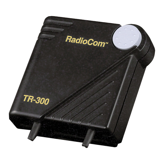
TR-300 BELT-PACK TRANSCEIVER TECHNICAL INFORMATION SPECIFICATIONS TR-300 Overall Power Requirements ...6 AA cells (Alkaline, NEDA, MN 1500) Nickel-metal hydride optional Current Drain...typical 82 mA Temperature Range ...-4°F to 130°F (-20°C to 55°C) Dimensions...4.25” W x 4.125” H x 2.0” D (108mm x 105mm x 51 mm) Weight ...13 oz (369g) with batteries... -
Page 12: Features
Lock-to-Transmit feature for the TR-300P. Headset Connector: A four pin XLR connec- tor for Input/Output. (Plug for Telex, Jack for RTS units). The headset jack will accept many different Telex model headsets. Compatible with other intercom headsets with four pin XLR connectors that are wired as shown in Figure 5. - Page 13 LOW BATTERY / OVERMODULATION INDICATOR LIGHT BELT CLIP HEADSET CONNECTOR BATTERY CHARGE TRANSMIT ANTENNA JACK External Controls, TR-300 TALK INDICATOR LIGHT PUSH-TO-TALK/ LOCK-TO-TALK SWITCH talk Bat/ talk ovmod VOLUME OFF/ON CONTROL RECEIVE ANTENNA Figure 6 -11-...
-
Page 14: Battery Compartment
ACCESS TO MICROPHONE GAIN CONTROL CANADA IIIIIIIIIII Figure 7 Internal controls, TR-300 Dynamic/Electret Switch: This switch allows selection of “D” when using a Dynamic Mi- crophone or “E” when using and Electret Mi- crophone. Battery Compartment: Holds 6 AA batteries in a removable battery holder (supplied). -
Page 15: Equipment Set-Up
Telex Audio Com and similar systems. Product No. 71280XXXX is set for RTS 2 wire and similar systems. Units originally set for Telex may be set to RTS and vice versa. Both models may be set to interface with Clearcom, and 4 wire RTS/McCurdy matrix type systems. - Page 16 Internal Auxiliary Audio Out Switch Settings Pin 1 Pin 2 Telex Audio Ground 600 ohm Balanced RTS 2 wire Ground 600 ohm Balanced Clearcom Ground 600 ohm Balanced 4 wire Ground Balanced Intercom HIGH Auxiliary Audio Input Pin 3 Pin1...
- Page 17 RACK MOUNTING To rack mount the BTR-300 base transceiver do the following: Remove the front two #6-32 x 3/8” screws on each side of the transceiver as shown in Figure 9. Attaching Brackets for Rack Mounting Place the rack mount brackets (supplied) on either side of the unit and insert three #6-32 x 3/8”...
-
Page 18: Antenna Information
ANTENNA CONNECTIONS The BTR-300 is supplied with two (2) anten- nas. One 5/8-wave antenna for Transmit and one 5/8-wave antenna for Transmit and one 5/8-wave for Receive. Assemble the 5/8-wave antenna by screwing the two sections together as shown in Figure 10. - Page 19 Remoting Antennas: It will be necessary to remote both the transmit and receive antennas on the BTR-300 when it is rack mounted. Connect the coax cable assembly (not sup- plied), to the receive antenna receptacle and mount the 5/8-wave antenna. The antenna can be attached to either a wall mount bracket or a microphone stand bracket (not supplied).
- Page 20 System’s overall performance. The following suggestions will result in optimum perfor- mance. Proper placement of the TR-300 can be criti- cal. The trailing antennas should “dangle” freely. “Wadding” the antennas up and placing them in a pocket, etc., will reduce system range.
- Page 21 RF signal at the BTR-300. See Figure 17. RadioCom ä TR-300 Placing the unit on top of a shelf or equipment rack unobstructed without remoting the antennas is GOOD.
- Page 22 Insert the headset/microphone into the 4 pin XLR connector on the front panel. See the mi- crophone connection diagram (Figure 2) if other than a Telex Headset is used. HEADSET MICROPHONE SELECT SWITCH If the headset you are using has an Electret microphone, the local microphone select switch must be in the “ELT”...
- Page 23 INTERCONNECTION to a HARD-WIRED INTERCOM SYSTEM The RADIOCOM wireless system can be integrated into Telex intercom systems and most existing wired intercom systems includ- ing RTS and Clearcom. Headset TR-300 Connect the intercom cable to the back of the BTR-300. There are two intercom connections...
- Page 24 BTR-300 is in the “OFF” position. Con- nect the AC power supply cord to the BTR at the socket labeled “POWER”. Plug the power supply unit into an AC outlet. PUSH PUSH Telex Communications Inc. Auxiliary Intercom BTR-300 Loop Thru Audio Input...
-
Page 25: Tr-300 Set-Up
“shelf worn” or “economical” batteries. Oper- ation from nickel metal hydride batteries is also permissible. Typical life of fresh alkaline batteries with the TR-300 is approximately 24 hours maximum, 15-17 hours is typical of fully charged nickel-metal hydride batteries. NOTE: Rechargeable batteries can be charged ri ght i n t he T R- 300 us i ng t h e T e l e x BC-300NM1 Battery Charger. -
Page 26: Pre-Walk-Thru Checklist
TR-300’s Connected the BTR-300 to any aux- iliary audio, intercom or external speaker. Installed batteries in the TR-300 Remote Transceiver. If you missed any of the above instructions, go back and complete that instruction before go- ing on. -
Page 27: System Operation
POWER If you have followed the instructions until this point, you should now be ready to turn both the TR-300 and the BTR-300 “ON”. Place the power switch on the BTR-300 in the “ON” position. The red power on indicator light should illuminate. -
Page 28: Tr-300 Operation
POWER You should now be ready to turn the TR-300 “ON”. Rotate the OFF/ON Volume Control Switch on the TR-300 clockwise to turn the unit on. BATTERY CHECK As you turn the unit on, note that the battery light (labeled bat/ovmod) should flash one or more times with good batteries. -
Page 29: Enabling Audio
PORTABLE TRANSCEIVERS Select the TR-300 portables that will be used with the BTR-300. Push in the portable enable switches that correspond to the TR-300 remotes that you will be using. The numbers of the portable stations (1, 2, 3, and 4), are the last digit of the product number on the back of the TR-300. -
Page 30: Setting System Gain Levels
TR-300 PORTABLE The overmodulation circuitry in the TR-300 uses the same light as the low battery cir- cuitry. If modulation is too high this light will illuminate when talking. -
Page 31: System Walk-Thru
· RF “Trouble Spots” · Operating distance beyond system capability. · Old or used batteries in the TR-300 Under normal conditions the Portable Trans- mit On lights on the BTR-300 should always be lit when portables are transmitting. “Weak Signal”... -
Page 32: Troubleshooting
Change the location of the base unit and antennas or avoid the bad areas with the remote beltpacks. Make sure the TR-300 beltpack is turned on - this will usually eliminate the interfer- ing signal. If not using a beltpack, make sure the corresponding enable switch at the base is disengaged. -
Page 33: Battery Information
The BC-300NM1 will charge nickel-metal hydride batteries in a TR-300. Insert the plug from the charger into the jack on the side of the TR-300 and plug the charger into a 110 volt outlet. Full charge of the battery pack is obtained af- ter 12 to 14 hours. - Page 34 BC-300NM2 BATTERY CHARGER NOTE: The BC-300NM2 is not supplied with the TR-300. See “Accessory” Section for or- dering information. Remove the battery holder from the TR-300. CAUTION DO NOT ATTEMPT TO CHARGE ANY ALKALINE BATTERIES WITH THIS CHARGER. Snap the terminal connector onto the battery holder and plug the charger into a 110 Volt outlet.
-
Page 35: Accessories
Order No. 730139-000 ACCESSORIES BC-300NM1 Battery Charger - Order No. 70741-001 Includes 6 nickel-metal hydride batteries and 1 carrier. Charges a TR-300 without removing the battery pack. BC-300NM2 Battery Charger Order No. 70741-002 Includes 6 nickel-metal hydride batteries and 1 carrier. Charges 1 set of batteries outside of the TR-300. -
Page 36: Customer Service Information
Telex reserves the right to make changes in design and improvement on its product without assuming any obligation to install the same on any of its products previously manufac- tured. -
Page 37: Fcc Information
United States Federal Communications Commission Parts 90 and 74. Licensing of Telex equipment is the user’s responsibility and licensability depends upon the user’s classification, user’s application, and frequency selected. Telex strongly urges the user to contact the ap- propriate telecommunications authority before ordering and choosing fre- quencies. - Page 38 TELEX COMMUNICATIONS, INC. 12000 Portland Ave. South, Burnsville, MN 55337, U.S.A. PN 803008-2 JAN 2001 Made in U.S.A...