
Related Manuals for Miller Electric STR 450 CE


Summary of Contents for Miller Electric STR 450 CE
- Page 1 OM-236 031B 2009−05 Effective with serial number 249 680 Processes Stick (SMAW) Welding TIG (GTAW) Welding Description Arc Welding Power Source STR 450 www.MillerWelds.com...
- Page 2 Warranty and service information for your particular model are also provided. Miller Electric manufactures a full line of welders and welding related equipment. For information on other quality Miller products, contact your local Miller...
-
Page 3: Table Of Contents
TABLE OF CONTENTS SECTION 1 − SAFETY PRECAUTIONS - READ BEFORE USING ....... . . 1-1. - Page 4 DECLARATION OF CONFORMITY for European Community (CE marked) products. ITW Welding Products Italy S.r.l. Via Privata Iseo 6/E, 20098 San Giuliano M.se, (MI) Italy declare that the product(s) identified in this declaration conform to the essential requirements and provisions of the stated Council Directive(s) and Standard(s). Product/Apparatus Identification: Product Stock Number...
-
Page 5: Section 1 − Safety Precautions - Read Before Using
SECTION 1 − SAFETY PRECAUTIONS - READ BEFORE USING som _2007−04 Protect yourself and others from injury — read and follow these precautions. 1-1. Symbol Usage DANGER! − Indicates a hazardous situation which, if Indicates special instructions. not avoided, will result in death or serious injury. The possible hazards are shown in the adjoining symbols or explained in the text. - Page 6 D Do not use welder to thaw frozen pipes. FUMES AND GASES can be hazardous. D Remove stick electrode from holder or cut off welding wire at contact tip when not in use. Welding produces fumes and gases. Breathing D Wear oil-free protective garments such as leather gloves, heavy these fumes and gases can be hazardous to your shirt, cuffless trousers, high shoes, and a cap.
-
Page 7: Additional Symbols For Installation, Operation, And Maintenance
1-3. Additional Symbols For Installation, Operation, And Maintenance FIRE OR EXPLOSION hazard. MOVING PARTS can cause injury. D Do not install or place unit on, over, or near D Keep away from moving parts such as fans. combustible surfaces. D Keep all doors, panels, covers, and guards D Do not install unit near flammables. -
Page 8: California Proposition 65 Warnings
1-4. California Proposition 65 Warnings For Gasoline Engines: Welding or cutting equipment produces fumes or gases which contain chemicals known to the State of California to Engine exhaust contains chemicals known to the State of cause birth defects and, in some cases, cancer. (California California to cause cancer, birth defects, or other reproduc- Health &... -
Page 9: Section 2 − Definitions
SECTION 2 − DEFINITIONS 2-1. Warning Label Definitions (For Wordless Labels) Warning! Watch Out! There are possible hazards as shown by the symbols. Electric shock from welding electrode or wiring can kill. 1.1 Wear dry insulating gloves. Do not touch electrode with bare hand. -
Page 10: Weee Label (For Products Sold Within The Eu)
Warning! Watch Out! There are possible hazards as shown by the symbols. Electric shock from wiring can kill. Disconnect input plug or power before working on machine. Read the Owner’s Manual before working on this machine. Consult rating label for input power requirements, and check power available at the job site −... -
Page 11: Symbols And Definitions
2-3. Symbols And Definitions Negative Weld Positive Weld Protective Earth Amperes Output Terminal Output Terminal (Ground) Supplementary Output Protector Shielded Metal Arc Volts Input Remote Welding (SMAW) Constant Current Rated Supply Rated Welding Duty Cycle (CC) Current Current Rated No-Load Rated Supply Load voltage Line Connection... -
Page 12: Section 3 − Installation
SECTION 3 − INSTALLATION 3-1. Specifications Amperes Input at Dimensions Rated Welding Ampere Rated Load Output, Open-Circuit (mm) Model KVA/KW Weight Output Range DC Rating 50/60 Hz, Three-Phase Voltage DC L x W x H 230 V 400 V 450 A @ 38 Volts DC, 25−450 A 80 V... -
Page 13: Volt-Ampere Curves
3-3. Volt-Ampere Curves The volt-ampere curves show the normal minimum and maximum voltage and amperage output capa- bilities of the unit. DC Amperes 3-4. Selecting A Location Lifting Eye Lifting Forks Use lifting eye or lifting forks to move unit. Movement If using lifting forks, extend forks beyond opposite side of unit. -
Page 14: Tipping
3-5. Tipping Do not move or operate unit where it could tip. 805 088 3-6. Weld Output Terminals and Selecting Cable Sizes Total Cable (Copper) Length In Weld Circuit Not Exceeding 150 ft 200 ft 250 ft 300 ft 350 ft 400 ft 100 ft (30 m) Or Less (45 m) -
Page 15: Remote 14 Receptacle Information
3-7. Remote Receptacle Information This unit automatically uses the remote control if connected to the remote receptacle. Socket* Socket Information REMOTE Contact closure to B completes 24 volts ac con- tactor control circuit. Contact closure to A completes 24 volts ac con- tactor control circuit. -
Page 16: Typical Connections For Stick (Smaw) Welding
3-8. Typical Connections For Stick (SMAW) Welding 805 089 / Ref. 803 310 3-9. Typical Connections For TIG (GTAW) Welding Remote output is always On in TIG mode. See Section 4-3 for scratch start TIG information. Hot Start function (for Stick weld- ing) is disabled in TIG mode. -
Page 17: Positioning Jumper Links
3-10. Positioning Jumper Links Disconnect and lockout/tag- out input power before installing or moving jumper links. Check input voltage available at site. Jumper Links Access Remove side panel. Jumper Link Label Check label − only one is on unit. Input Voltage Jumper Links Move jumper links to match input voltage. -
Page 18: Connecting Input Power
3-12. Connecting Input Power Installation must meet all Na- tional and Local Codes − have only qualified persons make this installation. Disconnect and lockout/tag- out input power before con- necting input conductors from unit. Always connect green or green/yellow conductor to supply grounding terminal GND/PE first, and never to a line ter-... -
Page 19: Section 4 − Operation
SECTION 4 − OPERATION 4-1. Controls Negative (−) Weld Terminal Power On-Off Switch Stick (SMAW) Welding Indicator Light Process Selection Switch Remote output is always On in TIG mode. Hot Start function (for Stick welding) is disabled in TIG mode. (GTAW) Welding Indicator Light... -
Page 20: Stick Start Procedure − Scratch Start Technique
4-2. Stick Start Procedure − Scratch Start Technique With Stick selected, start arc as follows: Electrode Workpiece Drag electrode across workpiece like striking a match; lift electrode slightly after touching work. If arc goes out electrode was lifted to high. If electrode sticks to workpiece, use a quick twist to free it. -
Page 21: Section 5 − Maintenance And Troubleshooting
SECTION 5 − MAINTENANCE AND TROUBLESHOOTING 5-1. Routine Maintenance Disconnect power before maintaining. n = Check Z = Change ~ = Clean l = Replace * To be done by Factory Authorized Service Agent Every Months l Damaged Or l Cracked Weld cables ~n Weld Connections Unreadable Labels Every... - Page 22 Trouble Remedy Erratic arc with excessive spatter. Use dry, properly stored electrodes. Shorten arc length. Reduce amperage setting. Electrode freezing to work. Increase amperage setting. Increase arc length. Use dry, properly stored electrodes. Low weld output with no control. Check position of Amperage Control (see Section 4-1). Limited output and low open-circuit Check incoming power for correct voltage.
- Page 23 Notes Work like a Pro! Pros weld and cut safely. Read the safety rules at the beginning of this manual. OM-236 031 Page 19...
-
Page 24: Section 6 − Electrical Diagrams
SECTION 6 − ELECTRICAL DIAGRAMS S9215056 Figure 6-1. Circuit Diagram For STR 450 OM-236 031 Page 20... - Page 25 S9215056 OM-236 031 Page 21...
-
Page 26: Section 7 − Parts List
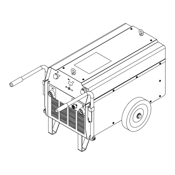
SECTION 7 − PARTS LIST Hardware is common and not available unless listed. 805 085 Figure 7-1. Case And Running Gear Dia. Item Part Mkgs. Description Quantity Figure 7-1. Case And Running Gear ....+156122078 . - Page 27 Hardware is common and not available unless listed. 11 − Figure 7-3 805 086 Figure 7-2. Main Assembly Item Dia. Part Description Quantity Mkgs. Figure 7-2. Main Assembly ....656089037 .
- Page 28 Item Dia. Part Description Quantity Mkgs. Figure 7-2. Main Assembly (Continued) ....056076152 . . . Socket, Dinse 50 Sq Mm ........
- Page 29 Notes Work like a Pro! Pros weld and cut safely. Read the safety rules at the beginning of this manual.
- Page 30 Notes Work like a Pro! Pros weld and cut safely. Read the safety rules at the beginning of this manual.
- Page 31 Effective January 1, 2009 This limited warranty supersedes all previous Miller warranties and is exclusive with no other guarantees or warranties expressed or implied. LIMITED WARRANTY − Subject to the terms and conditions 90 Days — Parts below, ITW Welding Products Italy warrants to its original retail MIG Guns purchaser that new Miller equipment sold after the effective date Induction Heating Coils and Blankets...
- Page 32 File a claim for loss or damage during Phone: 39 (0) 2982901 Fax: 39 (0) 298290-203 shipment. email: miller@itw−welding.it For assistance in filing or settling claims, contact your distributor and/or equipment manufacturer’s Transportation Department. © ORIGINAL INSTRUCTIONS − PRINTED IN USA 2009 Miller Electric Mfg. Co. 2009−01...