
Related Manuals for Miller Electric Blue Star 3500


Summary of Contents for Miller Electric Blue Star 3500
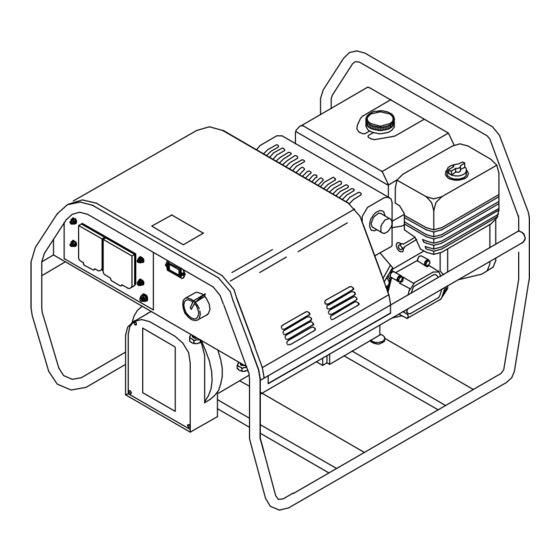
- Page 1 OM-498 197 849F March 2004 Processes Stick (SMAW) Welding Description Engine Driven Welding Generator Blue Star 3500 Visit our website at www.MillerWelds.com...
- Page 2 ISO 9001:2000 Quality System Standard. particular model are also provided. Miller Electric manufactures a full line of welders and welding related equipment. For information on other quality Miller products, contact your local Miller distributor to receive the latest full line catalog or individual catalog sheets.
-
Page 3: Table Of Contents
TABLE OF CONTENTS SECTION 1 − SAFETY PRECAUTIONS − READ BEFORE USING 1-1. Symbol Usage ............... . 1-2. -
Page 5: Section 1 − Safety Precautions − Read Before Using
SECTION 1 − SAFETY PRECAUTIONS − READ BEFORE USING Y Warning: Protect yourself and others from injury — read and follow these precautions. 1-1. Symbol Usage Means Warning! Watch Out! There are possible hazards with this procedure! The possible hazards are shown in the adjoining symbols. -
Page 6: Engine Hazards
WELDING can cause fire or explosion. Welding on closed containers, such as tanks, drums, or pipes, can cause them to blow up. Sparks can fly off from the welding arc. The flying sparks, hot workpiece, and hot equipment can cause fires and burns. Accidental contact of electrode to metal objects can cause sparks, explosion, overheating, or fire. -
Page 7: Compressed Air Hazards
STEAM AND HOT COOLANT can burn. D If possible, check coolant level when engine is cold to avoid scalding. D Always check coolant level at overflow tank, if pres- ent on unit, instead of radiator (unless told otherwise in maintenance section or engine manual). D If the engine is warm, checking is needed, and there is no overflow tank, follow the next two statements. -
Page 8: California Proposition 65 Warnings
READ INSTRUCTIONS. D Use only genuine MILLER/Hobart replacement parts. D Perform engine and air compressor (if applicable) maintenance and service according to this manual and the engine/air compressor (if applicable) manu- als. H.F. RADIATION can cause interference. D High-frequency (H.F.) can interfere with radio naviga- tion, safety services, computers, and communica- tions equipment. -
Page 9: Section 2 − Consignes De Sécurité − Lire Avant Utilisation
SECTION 2 − CONSIGNES DE SÉCURITÉ − LIRE AVANT Y Avertissement: Protégez vous et les autres des blessures − lisez et suivez ces précautions. 2-1. Signification des symboles Signifie Mise en garde ! Soyez vigilant ! Cette procédure présente des risques de danger ! Ceux-ci sont identifiés par des symboles adjacents aux directives. -
Page 10: Dangers Existant En Relation Avec Le Moteur
LES ACCUMULATIONS DE GAZ ris- quent de provoquer des blessures ou même la mort. D Fermer l’alimentation du gaz protecteur en cas de non utilisation. D Veiller toujours à bien aérer les espaces confinés ou se servir d’un respi- rateur d’adduction d’air homologué. LES RAYONS DE L’ARC peuvent pro- voquer des brûlures dans les yeux et sur la peau. -
Page 11: Dangers Liés À L'air Comprimé
L’EXPLOSION DE LA BATTERIE peut RENDRE AVEUGLE. D Toujours porter une protection faciale, des gants en caoutchouc et vêtements de protection lors d’une in- tervention sur la batterie. D Arrêter le moteur avant de débrancher ou de brancher les câbles de batterie. -
Page 12: Principales Normes De Sécurité
LE SURCHAUFFEMENT peut endom- mager le moteur électrique. D Arrêter ou déconnecter l’équipement avant de dé- marrer ou d’arrêter le moteur. D Ne pas laisser tourner le moteur trop lentement sous risque d’endommager le moteur électrique à cause d’une tension et d’une fréquence trop faibles. D Ne pas brancher de moteur de 50 ou de 60 Hz à... -
Page 13: Section 3 − Definitions
SECTION 3 − DEFINITIONS 3-1. Symbol Definitions Engine Choke Engine Oil Positive Hours Circuit Breaker SECTION 4 − SPECIFICATIONS NOTE This unit uses either a Kohler or a Honda engine. Differences between models are noted throughout this manual. 4-1. Weld, Power, And Engine Specifications Weld Welding Rated... -
Page 14: Dimensions, Weights, And Operating Angles
4-2. Dimensions, Weights, And Operating Angles Dimensions Height 20-3/4 in (527 mm) Width 22-3/4 in (577 mm) Depth 31-1/4 in (793 mm) 31-1/4 in (793 mm) 10-1/2 in (268 mm) 13-45/64 in (348 mm) 22-3/4 in (577 mm) 1-3/4 in (44 mm) 19-1/2 in (495 mm) 13/32 in (10 mm) Dia. -
Page 15: Fuel Consumption (Honda-Powered Units)
4-4. Fuel Consumption (Honda-Powered Units) 4-5. Duty Cycle 100% Duty Cycle at 80 Amperes CC/DC 3 Minutes Welding 30% Duty Cycle at 140 Amperes CC/DC Continuous Welding 7 Minutes Resting Return To Table Of Contents 802 121 Duty cycle is the percentage of 10 minutes that unit can weld at rated load without overheating. -
Page 16: Generator Power Curve
4-6. Generator Power Curve 4-7. Volt-Ampere Curves OM-498 Page 12 LOAD AMPS Return To Table Of Contents The ac generator power curves show the generator power available in amperes at the receptacles. 802 129 The volt-ampere curve shows the minimum and maximum voltage and amperage output capabilities of the welding generator. -
Page 17: Section 5 − Installation
SECTION 5 − INSTALLATION 5-1. Installing Welding Generator Movement Location 5-2. Grounding Generator To Truck Or Trailer Frame Electrically bond generator frame to vehicle frame by metal-to-metal contact. Airflow Clearance 18 in (460 mm) 18 in (460 mm) install1 5/02 − 802 512-A / Ref. 151 556 / 158 936-A / 800 652-A / S-0854 GND/PE Return To Table Of Contents 18 in... -
Page 18: Grounding Generator When Supplying Building Systems
5-3. Grounding Generator When Supplying Building Systems Use ground device as stated in electrical codes. 5-4. Engine Prestart Checks (Kohler-Powered Units) Closed Closed Open OM-498 Page 14 GND/PE 1/2 in (13 mm) Full Gasoline Full Return To Table Of Contents Equipment Grounding Terminal Grounding Cable... -
Page 19: Engine Prestart Checks (Honda-Powered Units)
5-5. Engine Prestart Checks (Honda-Powered Units) (13 mm) Open 5-6. Connecting The Battery (Honda Electric-Start Models Only) Tools Needed: 3/8, 1/2 in 1/2 in Full Gasoline Full Y Connect negative (−) cable last. Return To Table Of Contents Check all fluids daily. Engine must be cold and on a level surface. -
Page 20: Connecting To Weld Output Terminals
5-7. Connecting To Weld Output Terminals Tools Needed: 3/4 in 5-8. Selecting Weld Cable Sizes* Weld Output Terminals Y Stop engine before Welding connecting to weld out- Amperes put terminals. Y Do not use worn, dam- aged, undersized, or poorly spliced cables. This chart is a general guideline and may not suit all applications. -
Page 21: Section 6 − Operating The Welding Generator
SECTION 6 − OPERATING THE WELDING GENERATOR 6-1. Controls (Kohler-Powered Units) 60 Hz Weld and generator power output stops if generator overheats or engine speed is too low. Engine Switch Use switch to open ignition circuit, and to stop engine. Throttle Control Lever Use lever to select engine speed. -
Page 22: Controls (Honda-Powered Units) (See Section 6-3)
6-2. Controls (Honda-Powered Units) (See Section 6-3) Recoil-Start Electric-Start 60 Hz 802 099-A / 802 100-A / 953T-5-4 Return To Table Of Contents OM-498 Page 18... -
Page 23: Description Of Controls (Honda-Powered Units) (See Section 6-2)
6-3. Description Of Controls (Honda-Powered Units) (See Section 6-2) Weld and generator power output stops if generator overheats or engine speed is too low. Engine Switch On models with recoil-start, use switch to open ignition circuit, and to stop engine. On models with electric-start, use switch to open ignition circuit, and to start and stop en- gine. -
Page 24: Section 7 − Operating Auxiliary Equipment
SECTION 7 − OPERATING AUXILIARY EQUIPMENT NOTE The welding generator provides power while welding and with the Current control in any position. However, under these conditions equipment connected to the welding generator may be subject to larger than normal voltage fluctuations. It is recommended that only lamps be powered under these conditions. -
Page 25: Optional Generator Power Panels
7-2. Optional Generator Power Panels Generator Power Panel 495 315 (USA) Generator Power Panel 495 279 (Canada) Generator Power Panel 495 289 (Australia) Y If unit does not have GFCI recep- tacles, use GFCI-protected exten- sion cord. Y Power may still be present at a re- ceptacle when a circuit breaker trips. -
Page 26: Generator Power Panel Ratings
7-3. Generator Power Panel Ratings NOTE Unless otherwise stated, the rating of duplex outlets is the combined load of all receptacles. Total power from generator NOT to exceed 3500 Watts (60 Hz) Panel Protected Receptacle 495 218 495 315 (USA) 60 Hz 240 V CB1,2... -
Page 27: Wiring Instructions For Optional 120/240 Volt Twistlock Plug (Nema L14-30P)
7-4. Wiring Instructions For Optional 120/240 Volt Twistlock Plug (NEMA L14-30P) 120 V Notes 120V 240 V Return To Table Of Contents Plug Wired For 120/240 V, 3-Wire Load When wired for 120 V loads, each du- plex receptacle shares a load with one half of the 240 V receptacle. -
Page 28: Section 8 − Maintenance
SECTION 8 − MAINTENANCE 8-1. Routine Maintenance Check fluid levels. See Section 5-4 or 5-5. Service air cleaner element. See engine manual. Change oil. See engine manual and maintenance label. Clean Fuel sediment cup. Clean fuel tank and strainer. Repair or replace cracked cables. -
Page 29: Maintenance Label
NOTE Follow the storage procedure in the engine owner’s manual if the unit will not be used for an extended period. 8-2. Maintenance Label ENGINE MAINTENANCE 1.1 l (1.2 US qt, 1.94 lmp qt) Unleaded 86 + Octane 6.5 l (1.7 US Gal, 11.4 lmp pt) 50 h 8-3. -
Page 30: Adjusting Engine Speed (Kohler-Powered Units)
8-4. Adjusting Engine Speed (Kohler-Powered Units) Top View Tools Needed: OM-498 Page 26 ± 2000 150 rpm ± 3720 50 rpm (60 Hz) Top View Return To Table Of Contents After tuning engine, check engine speeds. See table for proper no load speeds. -
Page 31: Adjusting Engine Speed (Honda-Powered Units)
8-5. Adjusting Engine Speed (Honda-Powered Units) Tools Needed: 1/4, 3/8 in ± 1400 150 rpm ± 3720 50 rpm (60 Hz) Return To Table Of Contents After tuning engine, check engine speeds. See table for proper no load speeds. If necessary, adjust speeds as follows: Start engine and run until warm. -
Page 32: Section 9 − Troubleshooting
SECTION 9 − TROUBLESHOOTING 9-1. Troubleshooting A. Welding Trouble No weld output. Check Amperage control setting. Check weld connections. Be sure all equipment is disconnected from receptacles when starting unit. Have Factory Authorized Service Agent check brushes, slip rings, rotor, stator, reactor L2, output rectifier CR3, stabilizer L3, integrated rectifiers CR1 and CR2, and amperage control R1. - Page 33 Trouble Erratic output at generator power ac Check fuel level. receptacles. Check receptacle wiring and connections. Check throttle/governor linkage for smooth, non-binding operation. Service air cleaner according to engine manual. Check engine speed, and adjust if necessary (see Section 8-4 or 8-5). Output stops if engine speed is too low.
-
Page 34: Section 10 − Electrical Diagrams
SECTION 10 − ELECTRICAL DIAGRAMS 198 016-D Figure 10-1. Circuit Diagram For Welding Generator SC-495 297 Return To Table Of Contents OM-498 Page 30... - Page 35 201 026-A Figure 10-2. Wiring Diagram For Generator Power Panels (1 Of 2) Return To Table Of Contents OM-498 Page 31...
- Page 36 201 026-A Figure 10-3. Wiring Diagram For Generator Power Panels (2 Of 2) Return To Table Of Contents OM-498 Page 32...
-
Page 37: Section 11 − Generator Power Guidelines
SECTION 11 − GENERATOR POWER GUIDELINES NOTE The views in this section are intended to be representative of all engine-driven welding generators. Your unit may differ from those shown. 11-1. Selecting Equipment 11-2. Grounding Generator To Truck Or Trailer Frame Electrically bond generator frame to vehicle frame by metal-to-metal contact. -
Page 38: Grounding When Supplying Building Systems
11-3. Grounding When Supplying Building Systems 11-4. How Much Power Does Equipment Require? AMPERES x VOLTS = WATTS EXAMPLE 1: If a drill uses 4.5 amperes at 115 volts, calculate its running power requirement in watts. The load applied by the drill is 520 watts. EXAMPLE 2: If three 200 watt flood lamps are used with the drill from Example 1, add the individual loads to calculate total load. - Page 39 11-5. Approximate Power Requirements For Industrial Motors Industrial Motors Split Phase Capacitor Start-Induction Run Capacitor Start-Capacitor Run Fan Duty 11-6. Approximate Power Requirements For Farm/Home Equipment Farm/Home Equipment Stock Tank De-Icer Grain Cleaner Portable Conveyor Grain Elevator Milk Cooler Milker (Vacuum Pump) FARM DUTY MOTORS Std.
- Page 40 11-7. Approximate Power Requirements For Contractor Equipment Contractor Hand Drill Circular Saw Table Saw Band Saw Bench Grinder Air Compressor Electric Chain Saw Electric Trimmer Electric Cultivator Elec. Hedge Trimmer Flood Lights Submersible Pump Centrifugal Pump Floor Polisher High Pressure Washer 55 gal Drum Mixer Wet &...
- Page 41 11-8. Power Required To Start Motor Single-Phase Induction Motor Starting Requirements Motor Start Code KVA/HP kVA/HP x HP x 1000 VOLTS EXAMPLE: Calculate the starting amperage required for a 230 V, 1/4 HP motor with a motor start code of M. Volts = 230 HP = 1/4 11.2 x 1/4 x 1000...
- Page 42 11-10. Typical Connections To Supply Standby Power Y Properly install and ground this equipment according to its Owner’s Manual and national, state, and local codes. Utility Electrical Service Y Have only qualified persons perform these connections according to all applicable codes and safety practic- Y Properly install and ground this equipment according to its Owner’s Manual and national, state, and local...
- Page 43 11-11. Selecting Extension Cord (Use Shortest Cord Possible) Cord Lengths for 120 Volt Loads Y If unit does not have GFCI receptacles, use GFCI-protected extension cord. Current Load (Watts) (Amperes) 1200 1800 2400 3000 3600 4200 4800 5400 6000 *Conductor size is based on maximum 2% voltage drop Cord Lengths for 240 Volt Loads Y If unit does not have GFCI receptacles, use GFCI-protected extension cord.
-
Page 44: Section 12 − Stick Welding (Smaw) Guidelines
SECTION 12 − STICK WELDING (SMAW) GUIDELINES 12-1. Stick Welding Procedure Tools Needed: OM-498 Page 40 Return To Table Of Contents Y Weld current starts when electrode touches work- piece. Y Weld current can damage electronic parts in vehicles. Disconnect both battery cables before welding on a... -
Page 45: Electrode And Amperage Selection Chart
12-2. Electrode and Amperage Selection Chart 3/32 6010 5/32 & 3/16 6011 7/32 1/16 5/64 3/32 6013 5/32 3/16 7/32 3/32 5/32 7014 3/16 7/32 3/32 5/32 7018 3/16 7/32 3/32 5/32 7024 3/16 7/32 3/32 Ni-Cl 5/32 3/16 3/32 308L 5/32 12-3. -
Page 46: Positioning Electrode Holder
12-5. Positioning Electrode Holder ° End View of Work Angle ° End View of Work Angle 12-6. Poor Weld Bead Characteristics 12-7. Good Weld Bead Characteristics OM-498 Page 42 ° ° ° Side View of Electrode Angle GROOVE WELDS ° °... -
Page 47: Conditions That Affect Weld Bead Shape
12-8. Conditions That Affect Weld Bead Shape NOTE Weld bead shape is affected by electrode angle, arc length, travel speed, and thickness of base metal. Angle Too Small Too Short Slow 12-9. Electrode Movement During Welding NOTE Normally, a single stringer bead is satisfactory for most narrow groove weld joints; however, for wide groove weld joints or bridging across gaps, a weave bead or multiple stringer beads work better. -
Page 48: Butt Joints
12-10. Butt Joints 12-11. Lap Joint ° Or Less Single-Layer Fillet Weld 12-12. Tee Joint OM-498 Page 44 ° 1/16 in (1.6 mm) ° Or Less Multi-Layer Fillet Weld ° Or Less Return To Table Of Contents Tack Welds Prevent edges of joint from drawing together ahead of electrode by tack welding the materials in position be- fore final weld. -
Page 49: Weld Test
12-13. Weld Test 2 To 3 in (51-76 mm) 1/4 in (6.4 mm) 12-14. Troubleshooting − Porosity Possible Causes Arc length too long. Damp electrode. Workpiece dirty. 12-15. Troubleshooting − Excessive Spatter Possible Causes Amperage too high for electrode. Arc length too long or voltage too high. 2 To 3 in (51-76 mm) Porosity −... -
Page 50: Troubleshooting − Incomplete Fusion
12-16. Troubleshooting − Incomplete Fusion Possible Causes Insufficient heat input. Improper welding technique. Workpiece dirty. 12-17. Troubleshooting − Lack Of Penetration Lack of Penetration Good Penetration Possible Causes Improper joint preparation. Improper weld technique. Insufficient heat input. 12-18. Troubleshooting − Excessive Penetration Excessive Penetration Good Penetration Possible Causes... -
Page 51: Troubleshooting − Burn-Through
12-19. Troubleshooting − Burn-Through Possible Causes Excessive heat input. 12-20. Troubleshooting − Waviness Of Bead Possible Causes Unsteady hand. Use two hands. Practice technique. 12-21. Troubleshooting − Distortion Base metal moves in the direction of the weld bead. Possible Causes Excessive heat input. -
Page 52: Section 13 − Parts List
SECTION 13 − PARTS LIST Hardware is common and not available unless listed. 802 513-A / 802 153-B Figure 13-1. Main Assembly Return To Table Of Contents OM-498 Page 48... - Page 53 Item Dia. Part Mkgs....+495 247 ....Deleted .
- Page 54 Generator Power Panel 495 298 (USA) Generator Power Panel 495 218 (USA) Generator Power Panel 495 253 (South Africa) Generator Power Panel 495 290 (Europe) Generator Power Panel 495 283 (S.E. Asia) OM-498 Page 50 Hardware is common and not available unless listed. Generator Power Panel 495 315 (USA) Figure 13-2.
- Page 55 Item Dia. Part Mkgs. Figure 13-2. Generator Power Panels (Figure 13-1, Item 31) Generator Power Panel 495 298 (USA) ....495 220 . . . CB1, CB2 .
- Page 56 Notes Work like a Pro! Pros weld and cut safely. Read the safety rules at the beginning of this manual. Return To Table Of Contents OM-498 Page 52...
- Page 57 Notes...
- Page 58 Notes MATERIAL THICKNESS REFERENCE CHART 24 Gauge (.025 in) 22 Gauge (.031 in) 20 Gauge (.037 in) 18 Gauge (.050 in) 16 Gauge (.063 in) 14 Gauge (.078 in) 1/8 in (.125 in) 3/16 in (.188 in) 1/4 in (.25 in) 5/16 in (.313 in) 3/8 in (.375 in) 1/2 in (.5 in)
- Page 59 Warranty Questions? Call LIMITED WARRANTY − Subject to the terms and conditions below, Miller Electric Mfg. Co., Appleton, Wisconsin, warrants 1-800-4-A-MILLER to its original retail purchaser that new Miller equipment sold for your local after the effective date of this limited warranty is free of defects in material and workmanship at the time it is shipped by Miller.
- Page 60 For assistance in filing or settling claims, contact your distributor and/or equipment manufacturer’s Transportation Department. 2004 Miller Electric Mfg. Co. 1/04 Miller Electric Mfg. Co. An Illinois Tool Works Company 1635 West Spencer Street Appleton, WI 54914 USA International Headquarters−USA...