ATEN CL5816 User Manual
Lcd kvm switch
Hide thumbs
Also See for CL5816:
- User manual (100 pages) ,
- Specifications (4 pages) ,
- Quick start manual (2 pages)

Related Manuals for ATEN CL5816


Summary of Contents for ATEN CL5816
- Page 1 Questo manuale d’istruzione è fornito da trovaprezzi.it. Scopri tutte le offerte per Aten CL5816N cerca il tuo prodotto tra le migliori offerte di Switch LCD KVM Switch CL5808/CL5816 User Manual www.aten.com...
-
Page 2: Emc Information
CL5808/CL5816 User Manual EMC Information FEDERAL COMMUNICATIONS COMMISSION INTERFERENCE STATEMENT: This equipment has been tested and found to comply with the limits for a Class A digital device, pursuant to Part 15 of the FCC Rules. These limits are designed to provide reasonable protection against harmful interference when the equipment is operated in a commercial environment. -
Page 3: Sj/T 11364-2006
CL5808/CL5816 User Manual SJ/T 11364-2006 The following contains information that relates to China. -
Page 4: User Information
CL5808/CL5816 User Manual User Information Online Registration Be sure to register your product at our online support center: International http://eservice.aten.com Telephone Support For telephone support, call this number: International 886-2-8692-6959 China 86-10-5255-0110 Japan 81-3-5615-5811 Korea 82-2-467-6789 North America 1-888-999-ATEN ext 4988... -
Page 5: Package Contents
© Copyright 2009 - 2015 ATEN® International Co., Ltd. F/W Version: V1.0.082 Manual Date: 2015-04-24 ATEN and the ATEN logo are registered trademarks of ATEN International Co., Ltd. All rights reserved. All other brand names and trademarks are the registered property of their respective owners. -
Page 6: Table Of Contents
CL5808/CL5816 User Manual Contents EMC Information..........ii RoHS . - Page 7 CL5808/CL5816 User Manual LCD OSD Configuration ........26 The LCD Buttons .
- Page 8 CL5808 to Compatible 16-Port Switches ..... . 73 CL5816 to Compatible 8-Port Switches ..... . . 74 CL5816 to Compatible 16-Port Switches .
-
Page 9: About This Manual
CL5808/CL5816. Chapter 4, OSD Operation, provides a complete description of the CL5808/CL5816's OSD (On Screen Display), and how to work with it. Chapter 5, Keyboard Port Operation, details all of the concepts and procedures involved in the Hotkey operation of your CL5808/CL5816 installation. -
Page 10: Conventions
CL5808/CL5816 User Manual Conventions This manual uses the following conventions: Monospaced Indicates text that you should key in. Indicates keys you should press. For example, [Enter] means to press the Enter key. If keys need to be chorded, they appear together in the same bracket with a plus sign between them: [Ctrl+Alt]. -
Page 11: Introduction
(See the Appendix for a list of compatible ATEN switches). The CL5808/CL5816 is built on a modular design. The KVM section can be detached from the switch section for convenient maintenance and repair. - Page 12 Auto Scan feature also permits automatic scanning and monitoring of the activities of all computers running on the installation one by one. There is no better way to save time and money than with a CL5808/CL5816 installation. By using the CL5808/CL5816 with its sliding LCD console to manage your installation, you: eliminate the expense of having to purchase a separate keyboard, monitor, and mouse for each computer;...
-
Page 13: Features
1. Introduction Features Exclusive LED illumination light - designed by ATEN to illuminate the keyboard and touchpad and allow visibility in low-light conditions Integrated KVM console with 19” LED-backlit LCD in a Dual-Rail Slideaway housing Space saving technology – up to two consoles (one bus) control up to 8 or 16 computers Daisy chain up to 31 additional units –... - Page 14 CL5808/CL5816 User Manual * Only for computers connected with USB KVM cables. Extra console port – manage computers from an external console (monitor, USB or PS/2 keyboard and mouse) Supports external USB mouse Convenient direct port selector buttons (8 or 16) each with 2 LEDs that indicate whether the server is powered-on and selected.
-
Page 15: Requirements
1280 x 1024 @ 75 Hz. Make sure that none of the computer resolution settings exceed the LCD monitor's maximum resolution. PS/2 mouse and keyboard ports (6-pin Mini-DIN), or at least one USB port. Direct support Sun USB systems; or, for Sun legacy systems, an ATEN CV130A Sun Console Converter. Cables Substandard cables may damage the connected devices or degrade overall performance. -
Page 16: Operating Systems
CL5808/CL5816 User Manual PS/2-USB KVM cables 1.2 m 2L-5301UP 1.8 m 2L-5302UP 3.0 m 2L-5303UP Operating Systems Supported operating systems are shown in the table, below: Version Windows 2000 and higher Linux RedHat 7.1 and higher SuSE 9.0 and higher Mandriva (Mandrake) 9.0 and higher... -
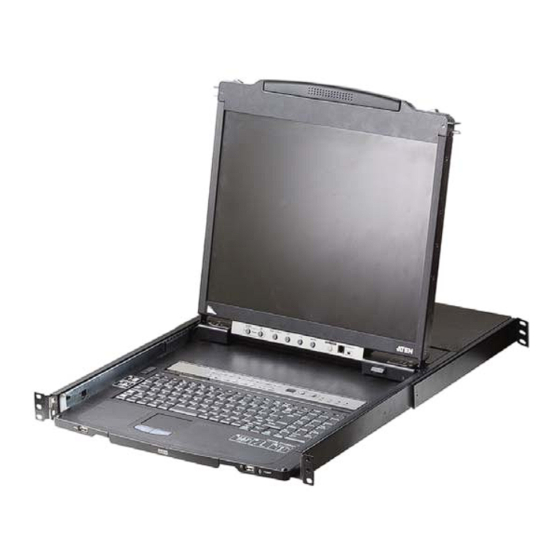
Page 17: Components
1. Introduction Components Front View Component Description Upper Handle Pull to slide the LCD module out; push to slide it in. See Opening the Console, page 19, for details on sliding the console in and out Module Release In order to slide the console out, you must first release it by Catches sliding these catches to the inside. -
Page 18: Keyboard Module
CL5808/CL5816 User Manual Keyboard Module Component Description Touchpad Standard mouse touchpad Keyboard Standard 105-key keyboard Port Selection To access a Port on the currently selected Station press its Buttons and LEDs corresponding port selection button. Indicator LEDs are built into the switches: An On Line LED lights to indicate that the computer attached to its corresponding port is up and running. -
Page 19: Lcd Module
Firmware Upgrade Port: The Firmware Upgrade Cable Upgrade that transfers the firmware upgrade data from the adminis- Section trator's computer to the CL5808/CL5816 plugs into this RJ-11 connector. Firmware Upgrade Switch: During normal operation this switch should be in the NORMAL position. (See The Firmware Upgrade Utility, page 57 for firmware upgrading details.) -
Page 20: Rear View
Grounding The grounding wire used to ground the switch attaches here. Terminal External For flexibility and convenience, the CL5808/CL5816 supports Console Port an independent, external, KVM console. If you choose to install an external console, the Console Cable (supplied with... -
Page 21: Hardware Setup
Keyboard Power On function. 3. Packing material has been inserted to protect the CL5808/ CL5816 during shipping. Slide the LCD module out (see Opening the Console, page 19, for details), until the packing material is visible. Remove the packing material before... -
Page 22: Standard Rack Mounting
CL5808/CL5816 User Manual Standard Rack Mounting A standard rack mounting kit is provided with your CL5808/CL5816. The kit enables the CL5808/CL5816 to be mounted in rack with a depth of 52–85 cm. L Brackets Side Mountng Brackets Note: 1. It takes two people to mount the switch: one to hold it in place, the other to screw it in. - Page 23 2. Hardware Setup To rack mount the CL5808/CL5816, do the following: 1. While one person positions the switch in the rack and holds it in place, the second person loosely screws the front brackets to the rack. 2. While the first person still holds the switch in place, the second person...
-
Page 24: Single Stage Installation
See KVM Cable Installation Diagrams, page 16. 4. Plug the power cord into the CL5808/CL5816 power socket and into a AC power source. After you have completed the installation procedures, power on the CL5808/ CL5816 (see Powering Off and Restarting, page 25 for details). -
Page 25: Single Stage Installation Diagram
2. Hardware Setup Single Stage Installation Diagram... -
Page 26: Cabling Diagrams
CL5808/CL5816 User Manual Cabling Diagrams Console Cable Installation Diagram PS/2 KVM Cable Installation Diagrams USB KVM Cable Connection PS/2 KVM Cable Connection... -
Page 27: Daisy Chaining
1. Use a daisy chain cable set (described in the Cables section, page 5), to connect the Chain Out port of the parent CL5808/CL5816 to the Chain In port of the child switch (first station out to second station in, second station out to third station in, etc.). -
Page 28: Daisy Chain Installation Diagram
CL5808/CL5816 User Manual Daisy Chain Installation Diagram... -
Page 29: Basic Operation
Chapter 3 Basic Operation Opening the Console The CL5808/CL5816's console consists of two modules: an LCD display module located under the top cover; and a keyboard / touch pad module below the LCD module. The modules can either slide together, or independently. This allows you to have the LCD display available for viewing while the keyboard / touch pad module is conveniently out of the way when not in use. - Page 30 CL5808/CL5816 User Manual (Continued from previous page.) 2. Pull the top panel all the way out until it clicks into place. 3. Rotate the top panel all the way back to expose the LCD screen.
-
Page 31: Opening Together
3. Basic Operation 4. Reach underneath and pull the keyboard module all the way out until it clicks into place. Opening Together Refer to the diagrams in the Opening Separately section as you do the following: 1. Pull the release catch and pull the top and bottom panels out until the keyboard module clicks into place. -
Page 32: Closing The Console
CL5808/CL5816 User Manual Closing the Console 1. Pull the release catches located on either side of the keyboard toward you to release the keyboard module, then slide the module slightly in. 2. Let go of the catches. Using the front handle, push the keyboard module... - Page 33 3. Basic Operation (Continued from previous page.) 3. Rotate the LCD module all the way down, then pull the rear catches to release the LCD module. 4. Using the front handle, push the module all the way in.
-
Page 34: Operating Precautions
CL5808/CL5816 User Manual Operating Precautions The maximum load bearing capacity of the keyboard module is 30kg. Failure to heed the information below can result in damage to the keyboard module. Right! Rest your hands and arms lightly on the keyboard module as you work. -
Page 35: Powering Off And Restarting
3. Basic Operation Powering Off and Restarting If it becomes necessary to power off the CL5808/CL5816, do the following before restarting it: 1. Shut down all the computers that are attached to the CL5808/CL5816. Note: Unplug the power cords of any computers that have the Keyboard Power On function. -
Page 36: Lcd Osd Configuration
CL5808/CL5816 User Manual LCD OSD Configuration The LCD Buttons The LCD OSD allows you to set up and configure the LCD display. Four buttons are used to perform the configuration, as described in the table, below: Button Function MENU When you have not entered the LCD OSD Menu function, pressing this button invokes the Menu function, and brings up the Main Menu. -
Page 37: Lcd Adjustment Settings
3. Basic Operation LCD Adjustment Settings An explanation of the LCD OSD adjustment settings is given in the table below: Setting Explanation Brightness Adjusts the background black level of the screen image. Contrast Adjusts the foreground white level of the screen image. Phase If pixel jitter or horizontal line noise is visible on the display, your LCD may have the wrong phase setting. -
Page 38: Hot Plugging
CL5808/CL5816 User Manual Hot Plugging The CL5808/CL5816 supports hot plugging – components can be removed and added back into the installation by unplugging and replugging their cables without the need to shut the unit down. In order for hot plugging to work properly, however, there are some procedures that need to be taken into account, as described in the following sections. -
Page 39: Port Switching
3. Basic Operation Port Switching The CL5808/CL5816 provides three port switching methods to access the computers on the installation: Manual, an OSD (on-screen display) menu system, and Hotkeys. Manual port switching is discussed below. See Chapter 4,OSD Operation and Chapter 3, Keyboard Port Operation for more information. -
Page 40: Port Id Numbering
CL5808/CL5816. Any computer connected to the CL5808/CL5816 can access the USB peripheral on a one-at-a-time basis. The peripheral device is available to computers connected to the CL5808/CL5816 on the same level only, and is not available to computers connected to daisy chained switches. -
Page 41: Osd Operation
Chapter 4 OSD Operation Overview The On Screen Display (OSD) is a menu driven method to handle computer control and switching operations. All procedures start from the OSD main screen. There are two ways to invoke the OSD: 1. Tap the OSD invocation key on the keyboard (see page 81), or 2. -
Page 42: Osd Main Screen
CL5808/CL5816 User Manual OSD Main Screen When you invoke the OSD, a screen similar to the one below appears: Note: 1. The diagram depicts the administrator's main screen. The user main screen does not show the F4 and F6 functions, since these are reserved for the administrator and can't be accessed by users. -
Page 43: Osd Main Screen Headings
4. OSD Operation OSD Main Screen Headings The table below describes the OSD Main Screen headings. Heading Description SN--PN This column lists the port ID numbers (station number - port number) for all the KVM ports on the installation. The simplest method to access a particular computer is move the highlight bar to it, then press [Enter]. -
Page 44: Osd Functions
CL5808/CL5816 User Manual OSD Functions OSD functions are used to configure and control the OSD. For example, you can rapidly switch to any port, scan selected ports, limit the list you wish to view, designate a port as a quick view port, create or edit a port name, or make OSD setting adjustments. -
Page 45: F2: List
4. OSD Operation F2: LIST This function lets you broaden or narrow the scope of which ports the OSD displays on the main screen. The submenu choices and their meanings are given in the table below. Choice Meaning Lists all of the ports on the installation that have been set accessible by the administrator for the current logged in user. -
Page 46: F3: Set
CL5808/CL5816 User Manual F3: SET This function allows the administrator and each user to set up his own working environment. A separate profile for each is stored by the OSD and is activated according to the username that was provided during login. - Page 47 4. OSD Operation (Continued from previous page.) Setting Function SCAN–SKIP Selects which computers will be accessed under skip mode (see MODE F5 SKP, page 42), and Auto Scan mode (see F7 SCAN, page 44. Choices are: ALL - All the ports which have been set accessible (see SET ACCESSIBLE PORTS, page 39);...
-
Page 48: F4: Adm
CL5808/CL5816 User Manual F4: ADM F4 is an administrator only function. It allows the administrator to configure and control the overall operation of the OSD. To change a setting double-click it, or use the up and down arrow keys to move the highlight bar to it then press [Enter]. - Page 49 4. OSD Operation Setting Function SET USER To record a fingerprint: LOGIN 1. Select an item from the list and double-click it, or move the high- (continued) light bar to it and press [Enter]. 2. Swipe the selected finger across the reader 3 times as directed. 3.
- Page 50 CL5808/CL5816 User Manual Setting Function EDIT PORT To help remember which computer is attached to a particular port, NAMES every port can be given a name. This function allows the administrator to create, modify, or delete port names. To edit a port name: 1.
- Page 51 3. Press [Esc] to exit. The operating system you selected is assigned to the KVM port. FIRMWARE In order to upgrade the CL5808/CL5816 firmware (see page 57), UPGRADE you must first enable Firmware Upgrade mode with this setting. When you bring up this menu, the current firmware version levels are displayed.
-
Page 52: F5: Skp
CL5808/CL5816 User Manual F5: SKP Clicking the F5 field or pressing [F5] invokes Skip mode. This function enables you to easily skip backward or forward – switching the console focus from the currently active computer port to the previous or next available one. -
Page 53: F6: Brc
4. OSD Operation F6: BRC F6 is an administrator only function. Clicking the F6 field, or pressing [F6], invokes Broadcast (BRC) mode. When this function is in effect, commands sent from the console are broadcast to all available computers on the installation. -
Page 54: F7: Scan
CL5808/CL5816 User Manual F7: SCAN Clicking the F7 field or pressing [F7] invokes Auto Scan mode. This function allows you to automatically switch among the available computers at regular intervals so that you can monitor their activity without having to take the trouble of switching yourself. -
Page 55: Keyboard Port Operation
Keyboard Port Operation Hotkey Port Control Hotkey port control allows you to provide KVM focus to a particular computer directly from the keyboard. The CL5808/CL5816 provides the following Hotkey port control features: Selecting the Active Port Auto Scan Mode Switching... -
Page 56: Hotkey Mode
CL5808/CL5816 User Manual Hotkey Mode Invoking Hotkey Mode All Hotkey operations begin by invoking Hotkey mode. There are two key sequences – a default and an alternate – that can be used to invoke Hotkey Mode, but only one of them can be active at a time: 1. -
Page 57: Selecting The Active Port
5. Keyboard Port Operation Selecting the Active Port Each KVM port is assigned a unique port ID (see Port ID Numbering, page 28). You can directly access any computer on the installation with a Hotkey combination that specifies the port ID of the KVM port that the computer is connected to. -
Page 58: Auto Scan Mode
CL5808/CL5816 User Manual Auto Scan Mode Auto Scan automatically switches among all the KVM ports that are accessible to the user at regular intervals, so that their activity can be monitored automatically. (See SCAN–SKIP MODE, page 37 for information regarding accessible ports.) -
Page 59: Skip Mode
5. Keyboard Port Operation Skip Mode Skip Mode allows you to switch between computers in order to monitor them manually. You can dwell on a particular port for as long as you like – as opposed to auto scanning, which automatically switches the port focus after a fixed interval. -
Page 60: Computer Keyboard/Mouse Reset
CL5808/CL5816 User Manual Computer Keyboard/Mouse Reset If either the keyboard or mouse stop functioning on the computer connected to the currently selected port, you can perform a keyboard/mouse reset on the computer with the following steps: 1. Invoke Hotkey mode (see page 46). -
Page 61: Hotkey Invocation Key Selection
5. Keyboard Port Operation Hotkey Invocation Key Selection The keys used to invoke Hotkey Mode (see Invoking Hotkey Mode, page 46) can be toggled between [Num Lock] + [-] and [Ctrl] + [F12] To toggle between them, do the following: 1. -
Page 62: Port Os Selection
After pressing a function key you automatically exit Hotkey mode. Restore the Default Values This administrator only Hotkey restores the CL5808/CL5816 default values (see RESTORE DEFAULT VALUES, page 40). To restore the CL5808/CL5816 to its default values, do the following: 1. Invoke Hotkey mode (see page 46). -
Page 63: Hotkey Summary Table
5. Keyboard Port Operation Hotkey Summary Table [Num Lock] + [A] [Enter] Enters Auto Scan mode. When Auto Scan mode is in effect, [P] or left [Q] [Enter] click pauses auto scanning. [Ctrl] + [F12] When auto scanning is paused, pressing any key or another left click resumes auto scanning. - Page 64 CL5808/CL5816 User Manual This Page Intentionally Left Blank...
-
Page 65: Keyboard Emulation
Chapter 6 Keyboard Emulation Mac Keyboard The PC compatible (101/104 key) keyboard can emulate the functions of the Mac keyboard. The emulation mappings are listed in the table below. PC Keyboard Mac Keyboard [Shift] Shift [Ctrl] Ctrl [Ctrl] [1] [Ctrl] [2] [Ctrl] [3] [Ctrl] [4] [Alt]... -
Page 66: Sun Keyboard
CL5808/CL5816 User Manual Sun Keyboard The PC compatible (101/104 key) keyboard can emulate the functions of the Sun keyboard when the Control key [Ctrl] is used in conjunction with other keys. The corresponding functions are shown in the table below. -
Page 67: The Firmware Upgrade Utility
Introduction The purpose of the Windows-based firmware upgrade utility is to provide an automated process for upgrading the CL5808/CL5816 and compatible adapter cable firmware. The program comes as part of a firmware upgrade package that is specific for each device. -
Page 68: Preparation
CL5808/CL5816 User Manual Preparation To prepare for the firmware upgrade, do the following: 1. Use the Firmware Upgrade Cable (provided with this unit), to connect a COM port on your computer to the Firmware Upgrade Port of your switch. Note: On a daisy chained installation, the chained stations will automatically receive the upgrade via the daisy chain cables. -
Page 69: Starting The Upgrade
7. The Firmware Upgrade Utility Starting the Upgrade To upgrade the firmware: 1. Run the downloaded firmware upgrade package file either by double clicking the file icon, or by opening a command line and entering the full path to it. The Firmware Upgrade Utility welcome screen appears: Note: The screens shown in this section are for reference only. - Page 70 CL5808/CL5816 User Manual The Firmware Upgrade Utility main screen appears. The devices capable of being upgraded are listed in the Device List panel: 4. Click Next to perform the upgrade. If you enabled Check Firmware Version, the utility compares the device's firmware level with that of the upgrade files.
-
Page 71: Upgrade Succeeded
7. The Firmware Upgrade Utility Upgrade Succeeded After the upgrade has completed, a screen appears to inform you that the procedure was successful: Click Finish to close the firmware upgrade utility. Upgrade Failed If the Upgrade Succeeded screen doesn't appear, it means that the upgrade failed to complete successfully. -
Page 72: Firmware Upgrade Recovery
CL5808/CL5816 User Manual Firmware Upgrade Recovery Below are three conditions that may result in requiring a firmware upgrade recovery: When a firmware upgrade is manually aborted. When the mainboard firmware upgrade fails. When the I/O firmware upgrade fails. To perform a firmware upgrade recovery, do the following: 1. -
Page 73: Appendix
Appendix Safety Instructions General This product is for indoor use only. Read all of these instructions. Save them for future reference. Follow all warnings and instructions marked on the device. Do not place the device on any unstable surface (cart, stand, table, or other surfaces). - Page 74 CL5808/CL5816 User Manual If an extension cord is used with this device make sure that the total of the ampere ratings of all products used on this cord does not exceed the extension cord ampere rating. Make sure that the total of all products plugged into the wall outlet does not exceed 15 amperes.
-
Page 75: Rack Mounting
Appendix Rack Mounting Before working on the rack, make sure that the stabilizers are secured to the rack, extended to the floor, and that the full weight of the rack rests on the floor. Install front and side stabilizers on a single rack or front stabilizers for joined multiple racks before working on the rack. -
Page 76: Consignes De Sécurité
CL5808/CL5816 User Manual Consignes de sécurité Général Ce produit est destiné exclusivement à une utilisation à l’intérieur. Veuillez lire la totalité de ces instructions. Conservez-les afin de pouvoir vous y référer ultérieurement. Respectez l’ensemble des avertissements et instructions inscrits sur l’appareil. - Page 77 Appendix L’équipement doit être installé à proximité de la prise murale et le dispositif de déconnexion (prise de courant femelle) doit être facile d’accès. La prise murale doit être installée à proximité de l’équipement et doit être facile d’accès. Veillez à ce que rien ne repose sur le cordon d’alimentation ou les câbles. Acheminez le cordon d’alimentation et les câbles de sorte que personne ne puisse marcher ou trébucher dessus.
- Page 78 CL5808/CL5816 User Manual L’unité a été exposée à la pluie ou à l’eau. L’unité est tombée ou le boîtier a été endommagé. Les performances de l’unité sont visiblement altérées, ce qui indique la nécessité d’une réparation. L’unité ne fonctionne pas normalement bien que les instructions d’utilisation soient respectées.
-
Page 79: Montage Sur Bâti
Appendix Montage sur bâti Avant de travailler sur le bâti, assurez-vous que les stabilisateurs sont bien fixées sur le bâti, qu’ils sont étendus au sol et que tout le poids du bâti repose sur le sol. Installez les stabilisateurs avant et latéraux sur un même bâti ou bien les stabilisateurs avant si plusieurs bâtis sont réunis, avant de travailler sur le bâti. -
Page 80: Technical Support
CL5808/CL5816 User Manual Technical Support International For online technical support – including troubleshooting, documentation, and software updates: http://eservice.aten.com For telephone support, Telephone Support, page iv North America Email Support support@aten-usa.com Online Troubleshooting http://www.aten-usa.com/support Technical Documentation Support Software Updates Telephone Support... -
Page 81: Specifications
Appendix Specifications Function CL5808N Computer Direct Connections 256 (via daisy chain) Port Selection OSD, Hotkeys, Pushbuttons Connectors External Console Port 1 x SPHD-18 (Male) External Mouse Port 1 x USB Type-A (Female) KVM Ports 8 x SPHD-17/18 (Female) Daisy Chain 1 x DB-25 (Male) FW Upgrade 1 x RJ-11 (Female) - Page 82 CL5808/CL5816 User Manual Function CL5816N Computer Direct Connections 512 (via daisy chain) Port Selection OSD, Hotkeys, Pushbuttons Connectors External Console Port 1 x SPHD-18 (Male) External Mouse Port 1 x USB Type-A (Female) KVM Ports 16 x SPHD-17/18 (Female) Daisy Chain...
-
Page 83: Connection Tables
Appendix Connection Tables The following tables indicate the relationship between the number of units and the number of computers that they control on a daisy chained installation. CL5808 to Compatible 8-Port Switches Computers Computers Computers Computers 1–8 65–72 129–136 193–200 9–16 73–80 137–144... -
Page 84: Cl5816 To Compatible 8-Port Switches
CL5808/CL5816 User Manual CL5816 to Compatible 8-Port Switches Computers Computers Computers Computers 1–16 73–80 137–144 201–208 17–24 81–88 145–152 209–216 25–32 89–96 153–160 217–224 33–40 97–104 161–168 225–232 41–48 105–112 169–176 233–240 49–56 113–120 177–184 241–248 57–64 121–128 185–192 249–256 65–72... -
Page 85: Supported Kvm Switches
Supported KVM Switches Up to 31 additional KVM switches can be daisy chained from the CL5808/ CL5816 . ATEN / Altusen KVM switches that can be used when configuring a daisy chained installation are shown in the following table: Model... -
Page 86: Clear Login Information
CL5808/CL5816 User Manual Clear Login Information If you are unable to perform an Administrator login (because the Username and Password information has become corrupted, or you have forgotten it), you can clear the login information with the following procedure. 1. Power off the switch and remove the top cover from the unit chassis. -
Page 87: Osd Factory Default Settings
Appendix OSD Factory Default Settings The factory default settings are as follows: Setting Default OSD Hotkey [Scroll Lock] [Scroll Lock] Port ID Display Position Upper Left Corner Port ID Display Duration 3 Seconds Port ID Display Mode Port Number plus the Port Name Scan Duration 5 Seconds Scan/Skip Mode... -
Page 88: Optional Rack Mounting
CL5808/CL5816 User Manual Optional Rack Mounting For convenience and flexibility, three optional rack mounting kits are available, as shown in the following table: Bracket Type Size (cm) Standard Installation – Long 70.0 – 105.0 Easy Installation – Short 57.0 – 70.0 Easy Installation –... - Page 89 Appendix 2. Attach the left and right easy-installation mounting rails to the inside of the rack. The flange that supports the switch will be to the inside. Rear Flange Slide Bar LEFT RAIL Rear Attachment Sliding Bracket Support Rear Flange Flange RIGHT RAIL...
- Page 90 CL5808/CL5816 User Manual (Continued from previous page.) 3. Slide the switch onto the support flanges. Use the screws supplied with this package to loosely attach the front of the switch to the front of the rack (only tighten the screws part way).
-
Page 91: Troubleshooting
There are ghost images on The distance between the external console and the the external monitor. CL5808/CL5816 is too great. The maximum VGA cable distance should not exceed 20m and, in some cases, may need to be shorter. Replace the VGA cable with one of an appropriately short length. -
Page 92: About Sphd Connectors
CL5808/CL5816 User Manual About SPHD Connectors This product uses SPHD connectors for its KVM and/or Console ports. We have specifically modified the shape of these connectors so that only KVM cables that we have designed to work with this product can be connected. - Page 93 Index Activate Beeper, 40 Easy installation rack mounting, 78 Active Port Edit Port Names, 40 selecting, 47 ADM, 38 Auto Scan Mode, 44, 48 F1 GOTO, 34 F2 LIST, 35 F3 SET, 36 Beeper, 40 F4 ADM, 38 BRC, 43 F5 SKP, 42 Broadcast Mode, 43 F6 BRC, 43...
- Page 94 CL5808 / CL5816 User Manual Summary Table, 53 Operating precautions, 24 Hotkey Mode Operating System exiting, 46 set, 41 invoking, 46 Optional rack mounting, 78 Hotkey Port Control, 45 Factory Default Settings, 77 Functions, 34 Installation Hotkey, 31, 36 Daisy Chaining, 17...
- Page 95 Index Reset Station IDs, 41 Logout Timeout, 39 Restarting, 25 Operating System, 41 Restore default values, 40 Quick View Ports, 40 RoHS, ii SJ/T 11364-2006, iii Skip Mode, 42, 49 SKP, 42 Safety Instructions Specifications General, 63 CL5708D / CL5708E, 71 Rack Mounting, 65 CL5708M / CL5708N, 71 SCAN, 44...