Table of Contents
Advertisement
Quick Links
Instructions – Parts List
POLYPROPYLENE AND PVDF
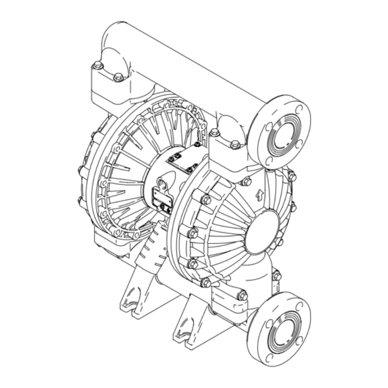
Huskyt 2150 Air-Operated
Diaphragm Pumps
2–inch AODD pump for fluid transfer applications. For professional
use only.
Not approved to European explosive atmosphere requirements.
See Models on page 2 for a list of pump models and descriptions.
120 psi (0.8 MPa, 8 bar) Maximum Fluid Working Pressure
120 psi (0.8 MPa, 8 bar) Maximum Air Input Pressure
Patent No.
CN ZL94102643.4
FR 9408894
JA 351720
US 5,368,452
Important Safety Instructions
Read all warnings and instructions in the
manual. Save these instructions.
See page 2 for table of contents.
308550ZAC
EN
04613B
Advertisement
Table of Contents

Related Manuals for Graco Huskyt 2150


Summary of Contents for Graco Huskyt 2150
- Page 1 Instructions – Parts List POLYPROPYLENE AND PVDF Huskyt 2150 Air-Operated Diaphragm Pumps 308550ZAC 2–inch AODD pump for fluid transfer applications. For professional use only. Not approved to European explosive atmosphere requirements. See Models on page 2 for a list of pump models and descriptions.
-
Page 2: Table Of Contents
..... . Graco Standard Warranty ..... . - Page 3 D Read all instruction manuals, tags, and labels before operating the equipment. D Use the equipment only for its intended purpose. If you are not sure, call your Graco distributor. D Do not alter or modify this equipment. Use only genuine Graco parts and accessories.
- Page 4 WARNING TOXIC FLUID HAZARD Hazardous fluid or toxic fumes can cause serious injury or death if splashed in the eyes or on the skin, inhaled, or swallowed. D Know the specific hazards of the fluid you are using. D Store hazardous fluid in an approved container. Dispose of hazardous fluid according to all local, state and national guidelines.
-
Page 5: Installation
Although pump use varies, a tance in planning a system to suit your needs. general guideline is to retorque fasteners every two D Always use Genuine Graco Parts and Accessories. months. Be sure all accessories are adequately sized and pressure-rated to meet the system’s requirements. - Page 6 Installation Grounding Ground all of this equipment: D Air Motor: Connect a ground wire and clamp as shown in Fig. 1. Loosen the grounding screw (W). Insert one end of a 12 ga (1.5 mm@) minimum ground wire (Y) behind the grounding screw and tighten the screw securely.
- Page 7 Installation Air Line b. Locate one bleed-type master air valve (B) close to the pump and use it to relieve trapped air. See the WARNING at left. Locate the other WARNING master air valve (E) upstream from all air line accessories and use it to isolate them during A bleed-type master air valve (B) is required in cleaning and repair.
- Page 8 3. Connect remaining ends of tubes to external air (0.1 MPa, 1 bar), diaphragm life will be shortened. signal, such as Graco’s Cycleflo (P/N 195264) or Cycleflo II (P/N195265) controllers. 4. See the Technical Data on page 34 for maximum suction lift (wet and dry).
- Page 9 Installation Flange Connections 1. Place a flat washer (E) on each bolt (C). Refer to Fig. 3. The fluid inlet and outlet ports are 2” raised face, standard 150 lb class pipe flanges. Connect 2” flanged 2. Align the holes in the gasket (B) and the pipe plastic pipe to the pump as follows.
- Page 10 Installation Changing the Orientation of the Fluid Inlet Fluid Pressure Relief Valve and Outlet Ports CAUTION The pump is shipped with the fluid inlet (R) and outlet (S) ports facing the same direction. See Fig. 4. To Some systems may require installation of a pres- change the orientation of the inlet and/or outlet port: sure relief valve at the pump outlet to prevent 1.
- Page 11 Installation Air Exhaust Ventilation The air exhaust port is 3/4 npt(f). Do not restrict the air exhaust port. Excessive exhaust restriction can cause erratic pump operation. WARNING If the muffler (P) is installed directly to the air exhaust FIRE AND EXPLOSION HAZARD port, apply PTFE thread tape or anti–seize thread Be sure to read and follow the warnings lubricant to the muffler threads before assembly.
-
Page 12: Operation
Operation Pressure Relief Procedure 1. Be sure the pump is properly grounded. Refer to Grounding on page 6. WARNING 2. Check all fittings to be sure they are tight. Be sure PRESSURIZED EQUIPMENT HAZARD to use a compatible liquid thread sealant on all The equipment stays pressurized until pressure is male threads. -
Page 13: Maintenance
Operation Operation of Remote Piloted Pumps NOTE: Leaving air pressure applied to the air motor for extended periods when the pump is not running may shorten the diaphragm life. Using a 3–way solenoid 1. Fig. 2 and Parts Drawings. Follow preceding steps valve to automatically relieve the pressure on the air 1 through 7 of Starting and Adjusting Pump. -
Page 14: Troubleshooting
Troubleshooting 1. Relieve the pressure before checking or servicing WARNING the equipment. To reduce the risk of serious injury whenever you are instructed to relieve pressure, always follow the 2. Check all possible problems and causes before Pressure Relief Procedure on page 12. disassembling the pump. - Page 15 Troubleshooting PROBLEM CAUSE SOLUTION Fluid in exhaust air. Diaphragm ruptured. Replace. See pages 19–22. Loose fluid side diaphragm plate Tighten or replace. See pages (105). 19–22. Pump exhausts excessive air at Worn air valve block (7), o-ring (6), Inspect; replace. See pages 16–17. stall.
-
Page 16: Service
Service Repairing the Air Valve Tools Required D Torque wrench D Torx (T20) screwdriver or 7 mm (9/32”) socket D Needle-nose pliers D O-ring pick D Lithium base grease NOTE: Air Valve Repair Kits 236273 (aluminum center housings) and 255061 (stainless steel center hous- ings) are available. - Page 17 Service Install with lips facing Rounded side must face down. Insert narrow end first. narrow end of piston (11). Grease. Insert wide end first. Tighten screws until they bottom out on the housing. 10{H 03947 Fig. 10 04901 Fig. 9 Reassembly 1.
-
Page 18: Ball Check Valve Repair
Service Ball Check Valve Repair Torque to 150–160 in–lb (17–18 NSm). See Torque Se- quence, page 32. Tools Required Arrow (A) must point toward outlet manifold (103). D Torque wrench Not used on some models. D 10 mm socket wrench D O-ring pick Disassembly NOTE: A Fluid Section Repair Kit is available. -
Page 19: Diaphragm Repair
Service Diaphragm Repair WARNING Tools Required To reduce the risk of serious injury whenever you D Torque wrench are instructed to relieve pressure, always follow the Pressure Relief Procedure on page 12. D 13 mm socket wrench D Adjustable wrench D 19 mm open–end wrench 1. - Page 20 Service 4. Unscrew one outer plate (105) from the diaphragm Reassembly – Standard Diaphragms shaft (24). Remove one diaphragm (401), and the 1. Grease the shaft u-cup packings (402*) and install inner plate (104). See Fig. 13. them so the lips face out of the housing (1). See Fig.
- Page 21 Reassembly – Overmolded Diaphragms 5. Assemble the other diaphragm assembly to the shaft as explained in step 2. This diaphragm will be lifted off the air cover at this point. WARNING 6. Supply the pump with low pressure air (less than 7 To reduce the risk of serious injury, including psi [0.05 MPa, 0.5 bar]).
- Page 22 Service 402* 403* 401* 04708 03982 Cutaway View, with Diaphragms in Place Cutaway View, with Diaphragms Removed 401* 403* Lips face out of housing (1). Air Side must face center housing (1). Grease. Used on Models with PTFE diaphragms only. Apply medium-strength (blue) LoctiteR or equivalent.
-
Page 23: Bearing And Air Gasket Removal
Service Bearing and Air Gasket Removal 7. Use a bearing puller to remove the diaphragm shaft bearings (19), air valve bearings (12) or pilot Tools Required pin bearings (15). Do not remove undamaged D Torque wrench bearings. D 10 mm socket wrench 8. - Page 24 Service Insert bearings tapered end first. Press-fit bearings flush with surface of center housing (1). Torque to 130–150 in-lb (15–17 NSm). Detail of Air Valve Bearings 03951 03952B Fig. 14 308550...
- Page 25 Notes 308550...
-
Page 26: Model No
Pump Matrix Husky 2150 Polypropylene and PVDF Pumps, Series A Your Model No. is marked on the pump’s serial plate. To determine the Model No. of your pump from the following matrix, select the six digits which describe your pump, working from left to right. The first digit is always D, designating Husky diaphragm pumps. -
Page 27: Repair Kit Matrix
Repair Kit Matrix For Husky 2150 Polypropylene and PVDF Pumps, Series A Repair Kits may be ordered separately. To repair the air valve, order Part No. 236273 for aluminum center housing models, or Part No. 255061 for stainless steel housing models (see page 28). Parts included in the Air Valve Repair Kit are marked with a symbol in the parts list, for example (4{H). -
Page 28: Parts
Parts Air Motor Parts List (Matrix Column 2) Ref. Ref. Digit Part No. Description Digit Part No. Description 188838 HOUSING, center; Same as F with the following exceptions aluminum 195921 HOUSING, center; 188854 COVER, air valve; remote, aluminum aluminum 195919 COVER, air;... - Page 29 Parts Fluid Section Parts List (Matrix Column 3) Ref. 189795 COVER, fluid; PVDF Digit Part No. Description 189789 MANIFOLD, inlet; PVDF 189793 COVER, fluid; polypropylene 189792 MANIFOLD, outlet; PVDF 189787 MANIFOLD, inlet; polypropylene 189298 PLATE, air side; aluminum 189790 MANIFOLD, outlet; polypropylene 189798 PLATE, fluid side;...
- Page 30 Parts Seat Parts List (Matrix Column 4) Diaphragm Parts List (Matrix Column 6) Ref. Ref. Digit Part No. Description Digit Part No. Description 201* 189288 SEAT; 316 stainless steel 401* DIAPHRAGM, backup; not sold polychloroprene (CR) separately 202* 112358 O-RING; PTFE 402* 112181 PACKING, u-cup;...
- Page 31 Parts H{17 401* 301* H{18 403* 201* 202* 17{H 10{H *402 *301 *201 202* Not used on some models. 04622D * These parts are included in the Pump Repair Kit, which may be purchased separately. Refer to the Repair Kit Matrix on page 27 to determine the correct kit for your pump. { These parts are included in Air Valve Repair Kit 236273 (aluminum center housing mod- els), which may be purchased separately.
-
Page 32: Torque Sequence
Torque Sequence Always follow torque sequence when instructed to torque fasteners. 1. Left/Right Fluid Covers 3. Outlet Manifold Torque bolts to 190–220 in–lb (21–25 NSm) Torque bolts to 150–160 in–lb (17–18 NSm) SIDE VIEW TOP VIEW 2. Inlet Manifold Torque bolts to 150–160 in–lb (17–18 NSm) BOTTOM VIEW 308550... -
Page 33: Dimensions
Dimensions FRONT VIEW 220.5 mm 280.5 mm 1/2 npt(f) 3/4 npt(f) Air Inlet 654 mm Air Exhaust (muffler included) 578 mm 489 mm 350.5 mm 89 mm 152.5 mm 501.5 mm SIDE VIEW PUMP MOUNTING HOLE PATTERN 6.25 in. Port Diameter: (159 mm) 2.20 in. -
Page 34: Technical Data
Technical Data Maximum fluid working pressure ..............120 psi (0.8 MPa, 8 bar) Air pressure operating range... -
Page 35: Performance Chart
Performance Chart Example of Finding Pump Air Consumption and Air Pressure at a Specific Fluid Delivery and Discharge Head: To supply 60 gpm (227 liters) fluid flow (horizontal scale) at 40 psi (0.28 MPa, 2.8 bar) discharge head pressure (vertical scale) re- quires approximately 60 scfm (1.68 m /min) air consumption at 70 psi (0.48 MPa, 4.8 bar) inlet air pressure. -
Page 36: Graco Information
With the exception of any special, extended, or limited warranty published by Graco, Graco will, for a period of five years from the date of sale, repair or replace any part of the equipment determined by Graco to be defective.