
Related Manuals for Dukane P220


Summary of Contents for Dukane P220
- Page 1 P220 ULTRASONIC PNEUMATIC PRESS SYSTEM USER MANUAL www.dukane.com ussales@dukane.com Globe-Am ENVELOPE...
- Page 2 The information contained in this manual is distributed on an “As is” basis, without warranty. While every precaution has been taken in the preparation of this manual, Dukane shall not have any liability to any person or entity with respect to any liability, loss, or damage caused or alleged to be caused directly or indirectly by the instructions contained in this manual, or by the hardware products described herein.
-
Page 3: Table Of Contents
Contents SECTION 1 - Introduction Introduction Press System Overview ........2 General User Information . - Page 4 E-Stop Switch Detail Generator Power SECTION 6 - Specifications Press Specifications Operating Environment Model Outline Drawings P220 System Number Guide P220 Generator Number Guide P220 Thruster Number Guide SECTION 7 - Alarm Messages Alarm Messages SECTION 8 - Maintenance System Maintenance...
-
Page 5: Section 1 - Introduction
SECTION Introduction 403-624-00 P220 Pneumatic Ultrasonic Press System USER MANUAL... -
Page 6: Introduction
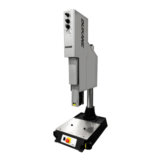
Introduction Press System Overview The P220 Pneumatic Ultrasonic Press System is used for welding thermoplastics. A typical P220 ultrasonic welding system is shipped completely with a press (thruster, base, and column), generator, an ultrasonic stack (transducer, booster, horn), fixturing, and cables. The optional HMI with IQ Explorer 3 software can be used for application setup and data acquisition. -
Page 7: Drawings And Tables
Condition Electrical Hearing or Practice Hazard Protection 403-624-00 P220 Pneumatic Ultrasonic Press System USER MANUAL... -
Page 8: Section 2 - Health And Safety
SECTION Health and Safety 403-624-00 P220 Pneumatic Ultrasonic Press System USER MANUAL... -
Page 9: General Considerations
Dukane Keep the Cover On - Do not remove any equipment covers unless directed does not assume any responsibility to do so by Dukane. Hazardous electrical voltages are present which could or liability for fixtures manufactured cause injury. -
Page 10: Ultrasonic Pressure
Wear ear protectors to reduce annoying or uncomfortable sounds. In addition, ultrasound baffles, sound enclosures, or materials that absorb sound may be located to surround the system. 403-624-00 P220 Pneumatic Ultrasonic Press System USER MANUAL... -
Page 11: Electrical Safety
Electrical Safety The P220 Pneumatic Ultrasonic Press Systems has several electrically powered components including: • P220 Generator • P220 Pneumatic Press Approved 2 pole, 3 wire grounding Each of these components must be grounded, including power receptacle HUBBELL No. 5252 or grounding and RFI suppression grounding. -
Page 12: Grounding For Rfi Suppression
This filter also prevents ultrasonic rFI from being fed back into the AC power line. Grounding wires are shipped with each system component (green/yellow; 5 meters long; Dukane part number 200-1557). It is important to connect each of these wires to the nearest grounded metal pipe or equivalent earth ground by means of a ground clamp. -
Page 13: Regulatory Agency Compliance
Control and Laboratory Use. manufactured. IP Rating The P220 generator has an IP (International Protection) rating from the IEC (International Electrotechnical Commission). The rating is IP2X, in compliance with finger-safe industry standards. The P220 generator complies with these standards as verified by TUV rheinland. -
Page 14: Section 3 - Installation
SECTION Installation 403-624-00 P220 Pneumatic Ultrasonic Press System USER MANUAL... -
Page 15: Before Installation
This effectively prevents access to the energy isolation points. See the locked/unlocked example of one such device in Fig. 3-1 and Fig. 3-2. Figure 3-1 Lockout Device In Open Position, Unlocked Figure 3-2 Bottom Lockout Device In Closed Position, Locked 403-624-00 P220 Pneumatic Ultrasonic Press System USER MANUAL... -
Page 16: Ac Power Requirements
Voltage / Current Part Number 200-1109 100-120V, 15A North America 200-1110 200-240V, 15A Europe 200-1111 200-240V, 16A India 200-1612 200-240V, 15A China 200-1876 200-240V, 16A Table 3 - 2 Standard IEC AC Power Cord Part Numbers 403-624-00 P220 Pneumatic Ultrasonic Press System USER MANUAL... -
Page 17: Unpacking The System
(Excludes horn and generator) Model Description P220TMED on 43P290 P220 PrESS SySTEM (with Base and Column) P220 THrUSTEr, MEDIUM SIZE, WITH DISTANCE P220TMED (Thruster Only without Base or Column) Table 3-3 Model Weights 403-624-00 P220 Pneumatic Ultrasonic Press System USER MANUAL... - Page 18 Then, carefully slide the press system on to the work area. It is recommended that the press base be secured to the workbench using the (2) holes indicated in Fig. 3-4. Figure 3-3 Pallet Lift Figure 3-4 Mounting Bolt Holes 403-624-00 P220 Pneumatic Ultrasonic Press System USER MANUAL...
-
Page 19: Air Supply Connections
Max. Particle Size (m) ------------------ 5.0 Max. Concentration (mg/m 3 ) --------- 5.0 Class 4 (or higher) 0 Max. Pressure Dew Point ( F) ----- +37.4 Max. Oil Content (mg/m ) ------------- 5.0 403-624-00 P220 Pneumatic Ultrasonic Press System USER MANUAL... -
Page 20: Cable Connections
DO NOT operate the generator unless the ultrasound coaxial cable is connected, and the transducer is installed in the thruster. Otherwise, an overload condition could occur, with possible damage to the generator. 403-624-00 P220 Pneumatic Ultrasonic Press System USER MANUAL... - Page 21 Generator AC Power Cord AC Line Plug (See Table 3-2) System Inputs/Outputs Cable (optional automation) J5 (System I/O) 200-2119-03M HMI Communications Cable (optional from the HMI) J9 (Ethernet/IP) 200-1552-03M Table 3-4 Cable Connections 403-624-00 P220 Pneumatic Ultrasonic Press System USER MANUAL...
-
Page 22: System Inputs/Outputs Signal Pinouts On The J5 Connector
CyCLE STArT INPUT which cannot be programmed to another function. 2) Inputs and Outputs can be re-programmed via the iQ Commander software. iQ Commander can be downloaded at the following link: http:/ /update.dukane.com 403-624-00 P220 Pneumatic Ultrasonic Press System USER MANUAL... -
Page 23: System Inputs/Outputs Signal Descriptions On The J5 Connector
This status output activates when the specified trigger type has occurred. It will remain active until the thruster head raises to the top of the stroke. This output will be an open circuit when a trigger condition hasn’t been detected. This status output can be re-programmed to Hold, In-Cycle, or In-Cycle with No Afterburst. 403-624-00 P220 Pneumatic Ultrasonic Press System USER MANUAL... - Page 24 This status output common is electrically isolated from chassis ground. For isolated sourcing (PNP) inputs, this common line would be connected to isolated ground potential. Using isolated sinking (NPN) output drivers, this common line would be connected to the isolated positive supply voltage output. 403-624-00 P220 Pneumatic Ultrasonic Press System USER MANUAL...
-
Page 25: Section 4 - Tooling Setup
SECTION Tooling Setup 403-624-00 P220 Pneumatic Ultrasonic Press System USER MANUAL... -
Page 26: Attaching The Fixture On The Base
WARNING Any fixture manufactured by a third party must comply with all OSHA and ANSI requirements. All fixtures must be guarded as necessary. Dukane does not assume any responsibility or liability for fixtures manufactured by the customer or any third party manufacturer. -
Page 27: Installing The Ultrasonic Stack Module
2. Turn off power to the generator by placing the AC switch in the “0” position. 3. Loosen all four transducer door screws as shown if Fig. 4-3, then set the door aside. Figure 4-2 E-STOP Button (ABOrT) Figure 4-3 Door removal Screws 403-624-00 P220 Pneumatic Ultrasonic Press System USER MANUAL... - Page 28 Figure 4-4 Inserting the Stack Figure 4-5 Placing the Stack Door 6. Tighten all four screws all the way as shown in Fig. 4-6. It's recommended to tighten them, using a Dukane torque wrench (part number 721-81), to 4.5 N-m (40 in-lbs).
-
Page 29: Adjusting The Thruster Position
Figure 4-7 Loosening Lock Handles Figure 4-8 raising/Lowering Thruster Position 403-624-00 P220 Pneumatic Ultrasonic Press System USER MANUAL... - Page 30 4. If desired, the orientation of the handles can be changed once they are locked. referring to Fig. 4-10, pull the handle straight out (1), rotate it in either direction (2), then release it (3). Figure 4-9 Tightening Lock Handles Figure 4-10 Handle Orientation 403-624-00 P220 Pneumatic Ultrasonic Press System USER MANUAL...
-
Page 31: Aligning The Fixture
If needed, move the horn up or down to aid in this step. 7. Tighten the hold-down cap screws by turning them clockwise until firm resistance is felt. 8. Reset the E-STOP. Figure 4-11 Fixture Leveling Screws 403-624-00 P220 Pneumatic Ultrasonic Press System USER MANUAL... -
Page 32: Section 5 - Controls And Indicators
SECTION Controls and Indicators 403-624-00 P220 Pneumatic Ultrasonic Press System USER MANUAL... -
Page 33: Control And Indicators Overview
Press System Figure 5-1 shows the controls and indicators for the press and generator. THRUSTER SUPPORT BASE GENERATOR Figure 5-1 Typical Press System 403-624-00 P220 Pneumatic Ultrasonic Press System USER MANUAL... -
Page 34: Press Controls And Indicators
Press Controls and Indicators PNEUMATIC CONTROLS AND GAUGE COLUMN LOCK POSITION HANDLES INDICATORS HORN MECHANICAL STOP E-STOP FIXTURE OPERATIONAL SWITCHES Figure 5-2 Thruster, Column, and Base 403-624-00 P220 Pneumatic Ultrasonic Press System USER MANUAL... -
Page 35: Pneumatic Controls, Gauge, And Ultrasound Indicator
The PrESSUrE GAUGE displays the air pressure set by the regulators. Pressure 1 (WELD PHASE) is shown by default. To view pressure 2 (HOLD PHASE), press and hold the PrESSUrE rEGULATOr 2 SELECTOr BUTTON. The ULTrASOUND ACTIVE INDICATOr is lit when energy is being supplied to the ultrasonic stack. 403-624-00 P220 Pneumatic Ultrasonic Press System USER MANUAL... -
Page 36: Pneumatic Components
When the bar is in the position shown in Fig. 5-4, the air flows through the valve. To disconnect the air supply from the press, push the bar to the left. 403-624-00 P220 Pneumatic Ultrasonic Press System USER MANUAL... -
Page 37: Position Indicators
In order to maintain the position of the MECHANICAL STOP, the MECHANICAL STOP LOCK SETSCrEW should be tightened in the direction of the arrow above. 403-624-00 P220 Pneumatic Ultrasonic Press System USER MANUAL... -
Page 38: Mechanical Stop Adjustment
3. rotate the MECHANICAL STOP ADJUSTMENT KNOB. As the knob is turned, the MECHANICAL STOP POSITION INDICATOr will move up or down. 4. Once the desired position has been reached, tighten the MECHANICAL STOP LOCK SCrEW. 403-624-00 P220 Pneumatic Ultrasonic Press System USER MANUAL... -
Page 39: Operating Safety Switch Detail
Operating Safety Switch Detail POWER LED ACTIVATION/ ACTIVATION AREA FAULT LED Figure 5-7 Operating Safety Switch E-Stop Switch Detail PUSH TO ACTIVATE TWIST CLOCKWISE TO RELEASE Figure 5-8 E-Stop (ABOrT) Switch 403-624-00 P220 Pneumatic Ultrasonic Press System USER MANUAL... -
Page 40: Generator Power
Generator Power GENERATOR POWER SWITCH POWER CORD Figure 5-9 Generator Power Switch and Cord 403-624-00 P220 Pneumatic Ultrasonic Press System USER MANUAL... -
Page 41: Section 6 - Specifications
SECTION Specifications 403-624-00 P220 Pneumatic Ultrasonic Press System USER MANUAL... -
Page 42: Press Specifications
Non-operating storage guidelines: Temperature: -4°F to 158°F (-20°C to +70°C) Air Particulates: Keep the equipment dry. Minimize exposure to moisture, dust, dirt, smoke and mold. Humidity: 5% to 95% Non–condensing @ 0°C to +30°C 403-624-00 P220 Pneumatic Ultrasonic Press System USER MANUAL... -
Page 43: Model Outline Drawings
P220 THrUSTEr, MEDIUM SIZE, WITH DISTANCE 400-2689 P220TMED on a 43P290 P220 PrESS SySTEM 400-2690 P220TMEB P220 THrUSTEr, MEDIUM SIZE, WITH DISTANCE AND FOrCE 400-2689 P220TMEF P220 THrUSTEr, MEDIUM SIZE, WITH FOrCE 400-2689 P220TMEN P220 THrUSTEr, MEDIUM SIZE (STANDArD W/ NO OPTIONS) 400-2689... -
Page 44: P220 System Number Guide
403-624-00 P220 Pneumatic Ultrasonic Press System USER MANUAL... -
Page 45: P220 Generator Number Guide
403-624-00 P220 Pneumatic Ultrasonic Press System USER MANUAL... -
Page 46: P220 Thruster Number Guide
403-624-00 P220 Pneumatic Ultrasonic Press System USER MANUAL... -
Page 47: Section 7 - Alarm Messages
SECTION Alarm Messages 403-624-00 P220 Pneumatic Ultrasonic Press System USER MANUAL... -
Page 48: Alarm Messages
Alarm Messages The following lists of alarms that may appear on the pneumatic press systems display or IQ Explorer 3 software. Information on particular alarms may also be obtained on the Dukane '"Easy Alarm" web page below: https:/ /support.dukane.com/EasyAlarm Alarm... - Page 49 Start the weld process sooner. U414 Max Trigger Delay Time Trigger delay distance was not reached within Increase maximum trigger delay time. Exceeded the specified time limit. Start the weld process sooner. 403-624-00 P220 Pneumatic Ultrasonic Press System USER MANUAL...
- Page 50 U502 End of Cycle Signal When Auto-stop is enabled and set for End of This alarm is for information only. Detected Cycle, this alarm indicates that the signal has been detected. 403-624-00 P220 Pneumatic Ultrasonic Press System USER MANUAL...
-
Page 51: Section 8 - Maintenance
SECTION Maintenance 403-624-00 P220 Pneumatic Ultrasonic Press System USER MANUAL... -
Page 52: System Maintenance
Disconnect t remove the thruster left and right side covers. 2. Check if any fasteners are visibly loose. If so, contact Dukane for the proper tightening torque. 3. Wipe or blow away all dirt and grease in the thruster. 4. Air is required for the normal operation of a pneumatic press. However, there may be a time when optional cooling accessories were added. -
Page 53: Contacting Dukane
Contacting Dukane Identify Equipment When contacting Dukane about a service–related problem, be prepared to give the following information: • Model number, line voltage and serial number. • Alarm/Fault indicators from the display. Software version (Press INFO. With selection indicators at System Information, press ENTER to get this data). -
Page 54: Dukane Iso Certification
Dukane chose to become ISO certified in order to demonstrate to our customers our continuing commitment to being a quality vendor. By passing its audit, Dukane can assure you that we have in place a well–defined and systematic approach to quality design, manufacturing, delivery and service. This certificate reinforces Dukane’s status as a quality vendor of technology and products. - Page 55 Please refer to our website at: www.dukane.com/contact-us to locate your local representative. 403-624-00 P220 Pneumatic Ultrasonic Press System USEr MANUAL...