Table of Contents
Advertisement
Quick Links
Advertisement
Table of Contents

Related Manuals for MSI WS WRX80


Summary of Contents for MSI WS WRX80
- Page 1 WS WRX80 Motherboard User Guide...
-
Page 2: Table Of Contents
Contents Quick Start........................3 Specifications ......................15 Special Features ......................19 Package Contents ...................... 20 Back Panel Connectors ..................... 21 1 Gbps LAN Port LED Status Table ..............21 10 Gbps LAN Port LED Status Table ..............22 Audio Jacks Connection ..................22 Installing Antennas .................... - Page 3 BAT1: CMOS Battery .................... 49 BMC_SW1: BMC Switch..................50 VGA_SW1: JVGA1 Switch ..................50 Onboard LEDs ......................51 EZ Debug LED ....................... 51 BMC LEDs ......................51 Debug Code LED ....................52 Boot Phases ......................52 Debug Code LED Table ..................52 Installing OS, Drivers ....................
-
Page 4: Quick Start
Quick Start Thank you for purchasing a new motherboard from MSI®. This Quick Start section provides demonstration diagrams about how to install your computer. Some of the installations also provide video demonstrations. Please link to the URL to watch it with the web browser on your phone or tablet. - Page 5 Safety Information ∙ The components included in this package are prone to damage from electrostatic discharge (ESD). Please adhere to the following instructions to ensure successful computer assembly. ∙ Ensure that all components are securely connected. Loose connections may cause the computer to not recognize a component or fail to start.
- Page 6 Case stand-off notification To prevent damage to the motherboard, any unnecessary mounting stand-off between the motherboard circuits and the computer case is prohibited. The Case standoff keep out zone signs will be marked on the backside of motherboard (as shown below) to serve as a warning to user.
- Page 7 Installing a Processor ⚽ ∙ https://youtu.be/yk4EpVUU03E...
- Page 8 Installing DDR4 memory ⚽ ∙ http://youtu.be/T03aDrJPyQs Memory module installation recommendation CPU Socket 1 DIMM 2 DIMMs AMD Ryzen™ 4 DIMMs Threadripper™ PRO Series Desktop Processors 6 DIMMs 8 DIMMs...
- Page 9 Connecting the Front Panel Header ⚽ ∙ http://youtu.be/DPELIdVNZUI Power LED Power Switch JFP1 Reserved HDD LED Reset Switch JFP1 HDD LED - HDD LED HDD LED + POWER LED - POWER LED POWER LED +...
- Page 10 Installing the Motherboard ⚽ ∙ https://youtu.be/wWI6Qt51Wnc Torque: 3 kgf·cm* *3 kgf·cm = 0.3 N·m = 2.6 lbf·in...
- Page 11 Connecting the Power Connectors ⚽ ∙ http://youtu.be/gkDYyR_83I4 ATX_PWR1 CPU_PWR2 CPU_PWR1...
- Page 12 Installing SATA Drives ⚽ ∙ http://youtu.be/RZsMpqxythc...
- Page 13 Installing a Graphics Card ⚽ ∙ http://youtu.be/mG0GZpr9w_A...
- Page 14 Connecting Peripheral Devices...
- Page 15 Power On...
-
Page 16: Specifications
Specifications ∙ Supports AMD Ryzen™ Threadripper™ PRO Series Processors* ∙ Supports sWRX8 socket * Please go to msi.com to get the newest support status as new processors are released. Chipset AMD® WRX80 Chipset ∙ 8x DDR4 memory slots, support up to 2TB* ∙... - Page 17 Continued from previous column ∙ Supports RAID 0, RAID 1, RAID5 and RAID10 for SATA storage devices RAID ∙ Supports RAID 0 and RAID 1 for M.2 NVMe storage devices Realtek® ALC4080 Codec Audio ∙ 7.1-Channel High Definition Audio ∙ Supports S/PDIF output 1x Aquantia®...
- Page 18 Continued from previous column ∙ 1x Water Flow meter connector ∙ 1x Front panel audio connector ∙ 2x System panel connectors ∙ 1x Chassis Intrusion connector ∙ 2x 2-pin Thermal Sensors connector System Connectors ∙ 1x TPM 2.0 module connector ∙...
- Page 19 Continued from previous column ∙ 1x 256 Mb flash ∙ UEFI AMI BIOS BIOS Features ∙ ACPI 6.2, SMBIOS 3.0 ∙ Multi-language ∙ BMC/IPMI Remote Management Operating System ∙ Windows 10/ 11 ∙ Drivers Software ∙ Enterprise Support Tool...
-
Page 20: Special Features
Special Features Audio Experience ∙ Audio Boost 5 ∙ Click BIOS 5 Network ∙ 10G LAN ∙ 1G LAN ∙ WiFi 6E Cooling ∙ Stacked Fin Array ∙ Frozr Heatsink Design ∙ M.2 Shield Frozr ∙ K7 thermal pad ∙ Choke pad ∙... -
Page 21: Package Contents
Package Contents Please check the contents of your motherboard package. It should contain: Board • 1x Motherboard Documentation • 1x Quick installation guide Application • 1x USB drive with drivers & utilities Cables • 2x SATA 6Gb/s cables • 2x Thermistor cables •... -
Page 22: Back Panel Connectors
Back Panel Connectors Item Description Clear CMOS button Wi-Fi Antenna connectors USB 3.2 Gen 2x2 20Gbps Type-C port (From Asmedia 3242) USB 3.2 Gen 2 10Gbps Type-C port (From AMD® WRX80 Chipset) USB 3.2 Gen 2 10Gbps Type-A ports (From AMD® WRX80 Chipset) Optical S/PDIF Out connector USB 3.2 Gen 2 10Gbps Type-A ports (From AMD®... -
Page 23: 10 Gbps Lan Port Led Status Table
10 Gbps LAN Port LED Status Table Link/ Activity LED Speed LED Status Description Status Speed No link 10 Mbps Green Linked Green 100 Mbps / 1 Gbps / 2.5 Gbps Blinking Data activity Yellow 10 Gbps Audio Jacks Connection Audio jacks to headphone and microphone diagram Audio jacks to stereo speakers diagram AUDIO INPUT... - Page 24 Audio jacks to 4-channel speakers diagram AUDIO INPUT Rear Front Audio jacks to 5.1-channel speakers diagram AUDIO INPUT Rear Front Center/ Subwoofer Audio jacks to 7.1-channel speakers diagram AUDIO INPUT Rear Front Side Center/ Subwoofer...
-
Page 25: Installing Antennas
Installing Antennas 1. Combine the antenna with the base. 2. Screw two antenna cables tight to the WiFi antenna connectors as shown. 3. Place the antenna as high as possible. -
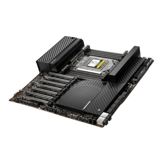
Page 26: Overview Of Components
Overview of Components CPU_PWR1 CPU_PWR2 JM_PSU2 JM_PSU1 ATX_PWR1 CPU_FAN1 M2_1 JUSB3 JPMBUS1 PCI_E1 M2_2 PCI_E2 JUSB4 PCI_E3 SATA▼1▲2 PCI_E4 SATA▼3▲4 SATA▼5▲6 PCI_E5 SATA▼7▲8 PCI_E6 U2_1 PCI_E7 U2_2... -
Page 27: Cpu Socket
CPU Socket 44.61 mm Distance from the center of the CPU to the nearest DIMM slot. 44.61 mm ⚽ Video Demonstration Watch the video to learn how to unbox and install CPU. https://youtu.be/yk4EpVUU03E Please use the AMD Torx screwdriver and follow the steps below to install the CPU. 1. - Page 28 3. Remove the protective pin cap, and then close and buckle the frame rail. Protective pin cap 4. Close the load plate, and then turn the load plate screws clockwise a little with the AMD Torx screwdriver in the sequence 1→2→3→1→2→3 until they are snug. AMD Torx screwdriver 5.
- Page 29 ∙ the CPU. ∙ Please retain the protective caps after installing the processor. MSI will deal with Return Merchandise Authorization (RMA) requests if only the motherboard comes with the protective caps on the CPU socket. When installing a CPU, always remember to install a CPU heatsink. A CPU heatsink ∙...
-
Page 30: Dimm Slots
DIMM Slots DIMMH1 DIMMG1 DIMMF1 DIMME1 DIMMA1 DIMMB1 DIMMC1 DIMMD1 Memory module installation recommendation CPU Socket 1 DIMM 2 DIMMs AMD Ryzen™ 4 DIMMs Threadripper™ PRO Series Desktop Processors 6 DIMMs 8 DIMMs DIMMC1 DIMMD1 DIMMC1... - Page 31 It is recommended to use a more efficient memory cooling system for full DIMMs ∙ installation or overclocking. The stability and compatibility of installed memory module depend on installed CPU ∙ and devices when overclocking. ∙ Please refer www.msi.com for more information on compatible memory.
-
Page 32: Pci_E1~7: Pcie Expansion Slots
PCI_E7: PCIe 4.0/3.0 x16 (From CPU) ⚠ Important If you install a large and heavy graphics card, you need to use a tool such as MSI ∙ Graphics Card Bolster to support its weight to prevent deformation of the slot. - Page 33 Multiple graphics cards installation recommendation PCI_E1 PCI_E1 PCI_E4 PCI_E1 PCI_E4 PCI_E7...
-
Page 34: M2_1~2: M.2 Slots (Key M)
M2_1~2: M.2 Slots (Key M) M2_1 M2_2 Installing M.2 module into M2_1 1. Loosen the screws of M.2 SHIELD FROZR heatsink. 2. Remove the M.2 SHIELD FROZR and remove the protective film from the thermal pad. 3. Remove the protective films from the M.2 thermal pads on the M.2 plate. - Page 35 4. If you install 2260 SSD, remove the screw from the M.2 plate and then install supplied EZ M.2 Clip kit on the M.2 plate. Skip this step if you install 2280 SSD. 2260 SSD 5. Insert your M.2 SSD into the M.2 slot at a 30-degree angle. 6.
- Page 36 Installing M.2 module into M2_2 1. Loosen the screws of M.2 SHIELD FROZR heatsink. 2. Remove the M.2 SHIELD FROZR and remove the protective film from the thermal pad. 3. Remove the protective films from the M.2 thermal pads on the M.2 plate. 4.
- Page 37 5. Insert your M.2 SSD into the M.2 slot at a 30-degree angle. 6. Rotate the EZ M.2 Clip to fix the M.2 SSD. 30º 30º 30º 30º 2280 SSD 2260 SSD 22110 SSD 7. Put the M.2 SHIELD FROZR heatsink back in place and secure it.
-
Page 38: Sata1~8: Sata 6Gb/S Connectors
SATA1~8: SATA 6Gb/s Connectors These connectors are SATA 6Gb/s interface ports. Each connector can connect to one SATA device. SATA2 SATA1 SATA4 SATA3 SATA6 SATA5 SATA8 SATA7 ⚠ Important Please do not fold the SATA cable at a 90-degree angle. Data loss may result during ∙... -
Page 39: U2_1~2: U.2 Connectors
U2_1~2: U.2 Connectors These connectors are U.2 interface ports. Each connector can connect to one PCIe 3.0 x4 NVMe storage device. ⚽ Video Demonstration Watch the video to learn how to Install U.2 SSD. http://youtu.be/KgFvKDxymvw Installing U.2 SSD 1. Connect the U.2 cable to the U.2 connector on the motherboard. -
Page 40: Jfp1, Jfp2: Front Panel Connectors
JFP1, JFP2: Front Panel Connectors The JFP1 connector controls the power on, power reset, and the LEDs on your PC case/chassis. Power Switch/ Reset Switch headers allow you to connect power button/ reset button. Power LED header connects to LED light on the PC case, and HDD LED header indicates the activity of the hard disk. -
Page 41: W_Flow1: Water Flow Meter Connector
W_FLOW1: Water Flow Meter Connector This connector allows you to connect a water flow meter to monitor the flow rate of your liquid cooling system. Signal Name Signal Name Ground WFLOW PWR WFLOW IN T_SEN1~2: Thermal Sensor Connectors These connectors allow you to connect the thermistor cable and use it to monitor the temperature of the detection point. -
Page 42: Cpu_Pwr1~2, Atx_Pwr1: Power Connectors
CPU_PWR1~2, ATX_PWR1: Power Connectors These connectors allow you to connect an ATX power supply. CPU_PWR1~2 Signal Name Signal Name Ground Ground Ground Ground +12V +12V +12V +12V ATX_PWR1 Signal Name Signal Name CPU_PWR1~2 +3.3V +3.3V Ground Ground Ground PWR OK 5VSB +12V ATX_PWR1... -
Page 43: Jci1: Chassis Intrusion Connector
JCI1: Chassis Intrusion Connector This connector allows you to connect the chassis intrusion switch cable. Normal Trigger the chassis (default) intrusion event Using chassis intrusion detector 1. Connect the JCI1 connector to the chassis intrusion switch/ sensor on the chassis. 2. -
Page 44: Jusb3: Usb 3.2 Gen 2 Type-C Connector
JUSB3: USB 3.2 Gen 2 Type-C Connector This connector allows you to connect USB 3.2 Gen 2 10Gbps Type-C connectors on the front panel. The connectors possess a foolproof design. When you connect the cable, be sure to connect it with the corresponding orientation. USB Type-C Cable JUSB3 USB Type-C port on... -
Page 45: Jusb1~2: Usb 2.0 Connectors
∙ In order to recharge your iPad, iPhone and iPod through USB ports, please install MSI Center utility. JTPM1: TPM Module Connector This connector is for TPM (Trusted Platform Module). Please refer to the TPM security platform manual for more details and usages. -
Page 46: Cpu_Fan1, Pump_Fan1, Sys_Fan1~6: Fan Connectors
CPU_FAN1, PUMP_FAN1, SYS_FAN1~6: Fan Connectors Fan connectors can be classified as PWM (Pulse Width Modulation) Mode or DC Mode. PWM Mode fan connectors provide constant 12V output and adjust fan speed with speed control signal. DC Mode fan connectors control fan speed by changing voltage. You can control fans in BIOS>... -
Page 47: Jpmbus1: Pmbus Connector
JPMBUS1: PMBus Connector This connector allows you to connect PMBus devices. Signal Name Signal Name VCC3 JM_PSU1~2: Multiple PSU Turn On Connectors These connectors use to turn on the multiple power supplies at the same time. Each connector can be connected to an additional power supply with a 24-pin to 2-pin adapter. -
Page 48: Jcom1: Serial Port Connector
JCOM1: Serial Port Connector This connector allows you to connect the optional serial port with bracket. Signal Name Signal Name SOUT Ground No Pin JVGA1: VGA Connector This connector allows you to connect a display for BMC. Signal Name Signal Name Green Blue DDC_DATA... -
Page 49: Jbat1: Clear Cmos (Reset Bios) Jumper
JBAT1: Clear CMOS (Reset BIOS) Jumper There is CMOS memory onboard that is external powered from a battery located on the motherboard to save system configuration data. If you want to clear the system configuration, set the jumpers to clear the CMOS memory. Keep Data Clear CMOS/ (default) -
Page 50: Bat1: Cmos Battery
BAT1: CMOS Battery If the CMOS battery is out of charge, the time in the BIOS will be reset and the data of system configuration will be lost. In this case, you need to replace the CMOS battery. Replacing CMOS battery 1. -
Page 51: Bmc_Sw1: Bmc Switch
BMC_SW1: BMC Switch This switch is used to enable/ disable the BMC. BMC enabled BMC disabled (Default) VGA_SW1: JVGA1 Switch This switch is used to enable/ disable the JVGA1 connector. JVGA1 enabled JVGA1 disabled (Default) ⚠ Important Always unplug the power cord from the power outlet before switching JVGA1. -
Page 52: Onboard Leds
Onboard LEDs EZ Debug LED These LEDs indicate the debug status of the motherboard. CPU - indicates CPU is not detected or fail. DRAM - indicates DRAM is not detected or fail. VGA - indicates GPU is not detected or fail. BOOT - indicates the booting device is not detected or fail. -
Page 53: Debug Code Led
Debug Code LED The Debug Code LED displays progress and error codes during and after POST. Refer to the Debug Code LED table for details. Hexadecimal Character Table Hexadecimal LED display Hexadecimal LED display Boot Phases Security (SEC) – initial low-level initialization Pre-EFI Initialization (PEI) –... - Page 54 PEI Progress Codes PEI Core is started Pre-memory CPU initialization is started 12 - 14 Pre-memory CPU initialization (CPU module specific) Pre-memory System Agent initialization is started 16 - 18 Pre-Memory System Agent initialization (System Agent module specific) Pre-memory PCH initialization is started 1A - 1C Pre-memory PCH initialization (PCH module specific) Memory initialization.
- Page 55 Memory initialization error. Invalid memory size or memory modules do not match Memory initialization error. No usable memory detected Unspecified memory initialization error Memory not installed Invalid CPU type or Speed CPU mismatch CPU self test failed or possible CPU cache error CPU micro-code is not found or micro-code update is failed Internal CPU error Reset PPI is not available...
- Page 56 Boot Device Selection (BDS) phase is started Driver connecting is started PCI Bus initialization is started PCI Bus Hot Plug Controller Initialization PCI Bus Enumeration 32 PCI Bus Request Resources PCI Bus Assign Resources Console Output devices connect Console input devices connect Super IO Initialization USB initialization is started USB Reset...
- Page 57 Runtime Set Virtual Address MAP Begin Runtime Set Virtual Address MAP End Legacy Option ROM Initialization System Reset USB hot plug PCI bus hot plug Clean-up of NVRAM Configuration Reset (reset of NVRAM settings) B8 - BF Reserved for future AMI codes DXE Error Codes CPU initialization error System Agent initialization error...
- Page 58 E4 - E7 Reserved for future AMI progress codes S3 Resume Error Codes S3 Resume Failed S3 Resume PPI not Found S3 Resume Boot Script Error S3 OS Wake Error EC - EF Reserved for future AMI error codes Recovery Progress Codes Recovery condition triggered by firmware (Auto recovery) Recovery condition triggered by user (Forced recovery) Recovery process started...
- Page 59 System is waking up from the S3 sleep state System is waking up from the S4 sleep state System has transitioned into ACPI mode. Interrupt controller is in PIC mode. System has transitioned into ACPI mode. Interrupt controller is in APIC mode.
-
Page 60: Installing Os, Drivers
Installing OS, Drivers Please download and update the latest utilities and drivers at www.msi.com Installing Windows 10/ Windows 11 1. Power on the computer. 2. Insert the Windows 10/ Windows 11 installation disc/USB into your computer. 3. Press the Restart button on the computer case. -
Page 61: Uefi Bios
UEFI has many new functions and advantages that traditional BIOS cannot achieve, and it will completely replace BIOS in the future. The MSI UEFI BIOS uses UEFI as the default boot mode to take full advantage of the new chipset’s capabilities. -
Page 62: Bios Setup
* When you press F10, a confirmation window appears and it provides the modification information. Select between Yes or No to confirm your choice. BIOS User Guide If you’d like to know more instructions on setting up the BIOS, please refer to https://download.msi.com/archive/mnu_exe/mb/AMDWRX80BIOS.pdf or scan the QR code to access. ⚠ Important... -
Page 63: Resetting Bios
Updating BIOS Updating BIOS with M-FLASH Before updating: Please download the latest BIOS file that matches your motherboard model from MSI website. And then save the BIOS file into the USB flash drive. Updating BIOS: 1. Switch to the target BIOS ROM by Multi-BIOS switch. Please skip this step if your motherboard doesn’t has this switch. - Page 64 ∙ This device may not cause harmful interference. ∙ This device must accept any interference received, including interference that may cause undesired operation. MSI Computer Corp. 901 Canada Court, City of Industry, CA 91748, USA (626)913-0828 www.msi.com...
- Page 65 ∙ ErP Directive 2009/125/EC Compliance with these directives is assessed using applicable European Harmonized Standards. The point of contact for regulatory matters is MSI-Europe: Eindhoven 5706 5692 ER Son. Products with Radio Functionality (EMF) This product incorporates a radio transmitting and receiving device. For computers in normal use, a separation distance of 20 cm ensures that radio frequency exposure levels comply with EU requirements.
- Page 66 20 cm ensures that radio frequency exposure levels comply with the Australian and New Zealand Standards. クラスB情報技術装置 この装置は 、 クラスB情報技術装置です 。 この装置は 、 家庭環境で使用することを目的とし ていますが 、 この装置がラジオやテレビジョン受信機に近接して使用されると 、 受信障害を 引き起こすことがあります 。 取扱説明書に従って正しい取り扱いをして下さい 。 VCCI-B KC인증서 상호: (주)엠에스아이코리아 제품명: 메인보드 모델명: 10-7D66 제조년월: 2022년 R-R-MSI-10-7D66 제조자 및 제조국가: MSI/중국...
- Page 67 ∙ Users should contact the local authorized point of collection for recycling and disposing of their end-of-life products. ∙ Visit the MSI website and locate a nearby distributor for further recycling information. ∙ Users may also reach us at gpcontdev@msi.com for information regarding proper Disposal, Take-back, Recycling, and Disassembly of MSI products.
- Page 68 MSI will comply with the product take back requirements at the end of life of MSI- branded products that are sold into the EU. You can return these products to local collection points.
- Page 69 MSI će poštovati zahtev o preuzimanju ovakvih proizvoda kojima je istekao vek trajanja, koji imaju MSI oznaku i koji su prodati u EU. Ove proizvode možete vratiti na lokalnim mestima za prikupljanje.
- Page 70 MSI si adeguerà a tale Direttiva ritirando tutti i prodotti marchiati MSI che sono stati venduti all’interno dell’Unione Europea alla fine del loro ciclo di vita.
- Page 71 Việt Nam RoHS Kể từ ngày 01/12/2012, tất cả các sản phẩm do công ty MSI sản xuất tuân thủ Thông tư số 30/2011/TT-BCT quy định tạm thời về giới hạn hàm lượng cho phép của một số hóa chất độc hại có trong các sản phẩm điện, điện tử”...
- Page 72 Alternatively, please try the following help resources for further guidance. ∙ Visit the MSI website for technical guide, BIOS updates, driver updates, and other information: http://www.msi.com ∙ Register your product at: http://register.msi.com Revision History ∙...