Table of Contents
Advertisement
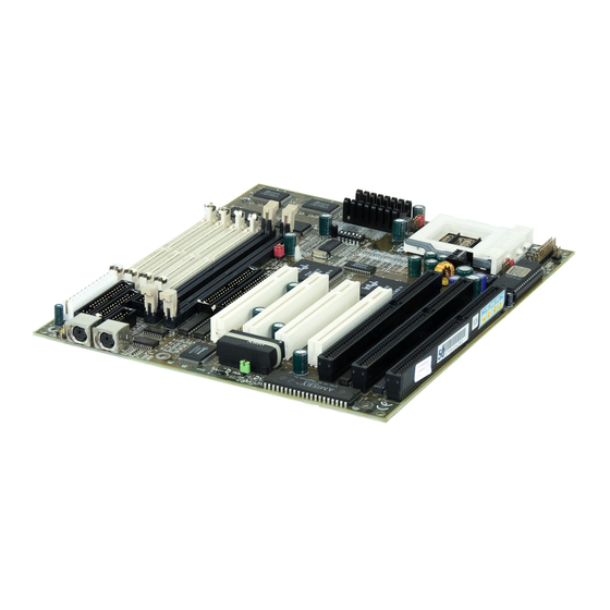
MSI-5149
Pentium TR10
Mainboard
Version 2.41
Intel and Pentium are registered trademarks of Intel Corporation.
PS/2 and OS/2 are registered trademarks of IBM Corporation.
Windows 95 and Windows NT are registered trademarks of Microsoft.
Netware is a registered trademark of Novell.
AMI is a registered trademark of American Megatrends Inc.
Award is a registered trademark of Award Software Inc.
AMD is a registered trademark of AMD.
Cyrix is a registered trademark of Cyrix.
Other brand, product names and trademarks are the properties of their respective
owners.
i
Advertisement
Table of Contents

Related Manuals for MSI MSI-5149


Summary of Contents for MSI MSI-5149
- Page 1 MSI-5149 Pentium TR10 Mainboard Version 2.41 Intel and Pentium are registered trademarks of Intel Corporation. PS/2 and OS/2 are registered trademarks of IBM Corporation. Windows 95 and Windows NT are registered trademarks of Microsoft. Netware is a registered trademark of Novell.
- Page 2 Manual Rev: 2.41 Release Date: September, 1997 FCC-B Radio Frequency Interference Statement This equipment has been tested and found to comply with the limits for a class B digital device, pursuant to part 15 of the FCC rules. These limits are designed to provide reasonable protection against harmful interference when the equipment is operated in a commercial environment.
- Page 3 Edition September 1997 Copyright Notice This manual is copyrighted. No guarantee is given as to the correctness of its contents. We reserve the right to make changes without notification. Trademarks All trademarks used in this manual are the property of their respective owners.
-
Page 4: Table Of Contents
Table of Contents Chapter 1: Introduction System Board Features ----------------------------------------------- System Board Layout-------------------------------------------------- Chapter 2: Hardware Installation Central Processing Unit: CPU--------------------------------------- CPU Installation Procedure------------------------------------- CPU Voltage Setting : JV1 - JV4, JV5------------------------ CPU Speed and Voltage Setting:: SW1 & JV1-JV4, JV5 -- CPU Fan Power Connector: JFAN----------------------------- CMOS RAM Clear: JRTC-------------------------------------- Memory Installation---------------------------------------------------... - Page 5 Hard Disk Connectors: IDE1 & IDE2------------------------------ 2-21 Power Supply Connector: JPW1------------------------------------- 2-22 Keyboard Connector: ATKBD--------------------------------------- 2-23 Mouse Connector: JM1----------------------------------------------- 2-24 IrDA Infrared Module Connector: IR------------------------------- 2-25 USB Connector: USB (Reserved)----------------------------------- 2-25 Chapter 3 AMI BIOS USER’S GUIDE Entering BIOS Setup-------------------------------------------------- Standard CMOS Setup------------------------------------------------ Advanced CMOS Setup----------------------------------------------- Advanced Chipset Setup----------------------------------------------...
- Page 6 Chipset Features Setup ----------------------------------------------- Power Management Setup ------------------------------------------- PNP/PCI Configuration ---------------------------------------------- 4-11 Load Setup Defaults -------------------------------------------------- 4-12 Integrated Peripherals------------------------------------------------- 4-13 Supervisor/User Password Setting----------------------------------- 4-15 IDE HDD Auto Detection-------------------------------------------- 4-16...
- Page 7 The MS-5149 is a high-performance personal computer mainboard. This ® ® ® mainboard supports Intel Pentium processors/Pentium processor with ™ technology, Cyrix ® 6x86/6x86L/6x86MX processors and AMD ® K6 processors.The system board supports the Peripheral Component Interconnect (PCI) Local Bus standard and provides four 32-bit PCI bus master slots.
-
Page 8: Cache Memory
® ® ® Socket 7 supports Intel Pentium processors and Pentium processor with MMX technology ® ® The Cyrix 6x86/6x86L/6x86MX and AMD K5/K6 processors are also supported. Chip Set ® Intel 82430 VX chip set. Cache Memory Supports 256K/512K pipelined burst cache memory. Supports Directed Map Organization and Write-Back cache policy. - Page 9 ATKBD JRTC1 JFAN JGL 1 JFM1 JGS1 MS-5149...
-
Page 10: Cpu Installation Procedure
® ® The MS-5149 motherboard operates with Intel Pentium processors/ ® ® Pentium processor with MMX technology, Cyrix 6x86/6x86L/6x86MX, ® and AMD 5K86/K6 processors. It could operate with 2.8V to 3.52V processors. The motherboard provides a 321-pin ZIF Socket 7 for easy CPU installation, a DIP switch (SW1) to set the proper speed for the CPU and a Jumper block (JV1 - JV4, JV5) for setting the CPU voltage. -
Page 11: Cpu Core Speed Derivation Procedure
2.1-2 CPU Core Speed Derivation Procedure 1. The 4 CPU clock frequencies that the system supports are 50 MHz, 55MHz, 60MHz and 66.6MHz (To adjust SW1 pin 1, 2 , and 3). See the following chart to set the different Host Clock Frequencies. CLOCK 50MHz 55MHz... -
Page 12: Cpu Voltage Setting: Jv1 - Jv4, Jv5
2.1-3 CPU Voltage Setting: JV1 - JV4, JV5 ATKBD JRTC1 J V 1 J V 2 J V 5 J V 3 J V 4 JFAN JGL 1 JFM1 JGS1 J V 1 J V 2 J V 3 J V 4 J V 1 J V 2 J V 3... -
Page 13: Cpu Speed And Voltage Setting: Sw1 & Jv1-Jv4, Jv5
2.1-3 CPU Speed and Voltage Setting: SW1 & JV1-JV4, JV5 To adjust the speed and voltage of the CPU, you must know the specifica- tion of your CPU (always ask the vendor for CPU specificaton). Then refer ® ® to Table 2.1 (Intel processors), Table 2.2 (Cyrix processors) and Table ®... -
Page 14: Cpu Voltage
® ® Table 2.1 Intel Pentium processors a. Intel ® Pentium ® processors CPU Voltage CPU Speed CPU Type JV1~JV4 VI/O Vcore 75MHz 90MHz 100MHz 120MHz 133MHz 150MHz 166MHz 200MHz b. Intel ® Pentium ® processors with MMX technology 166MHz 200MHz 233MHz... - Page 15 ® Table 2.2 Cyrix 6x86 processor ® Cyrix processor uses PR to rate the speed of their processors based on Intel ® processor core speed. For example P120+ (100MHz) has 120MHz core speed of an Intel ® processor but has 100MHz core speed in Cyrix ®...
- Page 16 ® Table 2.3 AMD K5 processor ® K5 processor uses PR to rate the speed of their processors based on ® Intel processor core speed. For example: P133+ (100MHz) has 133MHz core ® ® speed of Intel processor but has 100MHz core speed in AMD processor.
-
Page 17: Cpu Fan Power Connector: Jfan
2.1-4 CPU Fan Power Connector: JFAN This connector supports CPU cooling fan with +12V. It supports both two and three pin head connector. When connecting the wire to the connector, always take note that the red wire is the positive and should be connected to the +12V. -
Page 18: Cmos Ram Clear: Jrtc
2.1-5 CMOS RAM Clear: JRTC This jumper is for clearing the RTC data. +5V +3V USB1 JRTC clear keep Data (default) -
Page 19: Memory Bank Configuration
2.2-1 Memory Bank Configuration The system board supports a maximum of 128M of memory. It provides four 72-pin SIMMs (Single In-Line Memory Module) and two 168-pin DIMM sockets. This board supports 4 banks wherein each bank supports memory ranging from 4MB to 32MB. A Bank always has a pair of SIMM or a single DIMM. -
Page 20: Memory Installation Procedures
2.2-2 Memory Installation Procedures: A. How to install a SIMM Module Notched Single Sided SIMM Double Sided SIMM 1. The SIMM slot has a “Plastic Safety Tab” and the SIMM memory module has a “Notched End”, so the SIMM memory module can only fit in one direction. - Page 21 B. How to install a DIMM Module Single Sided DIMM Double Sided DIMM 1. The DIMM slot has a two key mark “VOLT and DRAM” , so the DIMM memory module can only fit in one direction. 2. Insert the DIMM memory module vertically into the DIMM slot. Then, push it in.
- Page 22 A.1 DIMM Power Voltage Selector : J2 +5V +3V +5V +3V USB1 DIMM Voltage + 5 V + 3 V 3.3V + 5 V + 3 V DIMM Power Level : 3.3V or 5V SIMM Power Level : Fixed at 5V 2-13...
- Page 23 2.2-3 Memory Population Rule 1. Make sure that the SIMM banks are using the same type and equal size density memory. 2. To operate properly, at least two 72-pin SIMM module must be installed in the same bank or one 168-pin DIMM module must be installed. The system cannot operate with only one 72-pin SIMM module.
- Page 24 The Turbo LED, Turbo Switch, Hardware Reset, Key Lock, Power LED, Power Saving LED, Sleep Switch, Speaker and HDD LED are all connected to the JFP connector block. +5V +3V USB1 Speaker Power LED Keylock P o w e r P o w e r S a v i n g S a v i n g...
-
Page 25: Power Led
2.3-1 Turbo LED The Turbo LED is used to monitor if the turbo switch is ON/OFF. You can connect the Turbo LED from the system case to this pin. (See Figure 2.1) 2.3-2 Hardware Reset Reset switch is used to reboot the system rather than turning the power ON/ OFF. - Page 26 Attach a a power saving switch to this connector. When the switch is pressed, the system immediately goes into suspend mode. Press any key and the system wakes up. +5V +3V USB1 JGL1 JGS1 2-17...
- Page 27 The system board has two connectors for serial ports COM1 and COM2. These two ports are 16550A high speed communication ports that send/ receive 16 bytes FIFOs. You can attach a mouse or a modem cable directly into these connectors. COM1 COM2 +5V +3V...
- Page 28 The system board provides a connector for LPT. A parallel port is a standard printer port that also supports Enhanced Parallel Port(EPP) and Extended capabilities Parallel Port(ECP). +5V +3V USB1 2-19...
- Page 29 The system board also provides a standard floppy disk connector FDD that supports 360K, 720K, 1.2M, 1.44M and 2.88M floppy disk types. You can attach a floppy disk cable directly to this connector. +5V +3V USB1 2--20...
- Page 30 The system board has a 32-bit Enhanced PCI IDE Controller that provides for two HDD connectors IDE1 (primary) and IDE2 (secondary). You can connect up to four hard disk drives, CD-ROM, 120MB Floppy (reserved for future BIOS) and other devices to IDE1 and IDE2. Primary IDE Connector +5V +3V USB1...
- Page 31 ® JPW1 is a standard 12-pin AT connector. Be sure to attach the connectors with the two black wires at the center. Power Connector +5V +3V USB1 Description Description Power Good Ground +5V DC Ground +12V DC -5V DC -12V DC +5V DC Ground +5V DC...
- Page 32 ® The system board provides a standard AT keyboard mini DIN connector for attaching a keyboard. You can plug a keyboard cable directly to this connector. ATKBD JRTC1 P i n 5 P i n 1 C L K P i n 2 P i n 4 P i n 3 V C C...
- Page 33 ® The system board provides a 5-pin connector for PS/2 mouse cable ® ® (optional). You can plug a PS/2 mouse to PS/2 mouse cable. The connector location is shown below. ATKBD JRTC1 DATA JFAN JGL 1 JFM1 JGS1 2-24...
- Page 34 The system board provides a 5-pin infrared connector(IR) for IR module. This connector is for optional wireless transmitting and receiving infrared module. You must configure the setting through BIOS setup. V C C N C R X G N D TX +5V +3V USB1 This 10-pin connector supports USB devices.
-
Page 35: Chapter 3 Ami Bios User's Guide
® Chapter 3 AMI BIOS USER’S GUIDE Chapter 3 ® BIOS USER GUIDE The system configuration information and chipset register information is stored in the CMOS RAM. This information is retained by a battery when the power is off. Enter the BIOS setup (if needed) to modify this information. -
Page 36: Entering Bios Setup
® Chapter 3 AMI BIOS USER’S GUIDE 3.1 Entering BIOS Setup ® Enter the AMI setup Program's Main Menu as follows: 1.Turn on or reboot the system. The following screen appears with a series of diagnostic check AMIBIOS (C) 1997 American Megatrends Inc., Hit <DEL>... -
Page 37: Standard Cmos Setup
® Chapter 3 AMI BIOS USER’S GUIDE 3. After pressing <DEL> key, the BIOS Setup screen (as below) will display AMIBIOS SETUP - BIOS SETUP UTILITIES (C) 1997 American Megatrends, Inc. All Rights Reserved Standard CMOS Setup Advanced CMOS Setup Advanced Chipset Setup Power Management Setup PCI / Plug and Play Setup... - Page 38 ® Chapter 3 AMI BIOS USER’S GUIDE 3.2 STANDARD CMOS SETUP Press <ENTER> on "Standard CMOS Setup" of MAIN MENU SCREEN and the above screen appears. AMIBIOS SETUP - STANDARD CMOS SETUP (C)1997 American Megatrends, Inc. All Rights Reserved Date (mm/dd/yyyy) : Wed, Mar 20, 1997 Time (hh/mm/ss) : 16:19:52...
- Page 39 ® Chapter 3 AMI BIOS USER’S GUIDE 3.3 Advanced CMOS Setup Press <ENTER> on "Advanced CMOS Setup" of MAIN MENU SCREEN and the screen as below will display. AMIBIOS SETUP - ADVANCED CMOS SETUP (C)1997 American Megatrends, Inc. All Rights Reserved Boot From SCSI Disabled Available Options:...
- Page 40 ® Chapter 3 AMI BIOS USER’S GUIDE A short description of this screen's items follows: Boot From The BIOS will check whether to boot SCSI from SCSI or not. Default setting is Disable. The BIOS first attempts to boot from BootUp drive A: and then, if unsuccessful, Sequence...
- Page 41 ® Chapter 3 AMI BIOS USER’S GUIDE Choose display type as EGA/VGA or Primary Display MONO. Password Check Choose Setup, or Always. "Setup" requires a password to enter BIOS setup. "Always" requires a password on Boot Up to load operating system, or enter BIOS Setup.
- Page 42 ® Chapter 3 AMI BIOS USER’S GUIDE Choose whether the ISA ROM using C800,16K (C800,16K) should be shadowed or not. Shadow: CC00,16K Choose whether the ISA ROM using (CC00,16K) should be shadowed or Shadow: not. Choose whether the ISA ROM using D000,16K Shadow: (D000,16K) should be shadowed or...
-
Page 43: Advanced Chipset Setup
® Chapter 3 AMI BIOS USER’S GUIDE 3.4 ADVANCED CHIPSET SETUP Press <ENTER> on "Advanced Chipset Setup" of MAIN MENU SCREEN and the screen as below will display. AMIBIOS SETUP - ADVANCED CHIPSET SETUP (C)1997 American Megatrends, Inc. All Rights Reserved Memory Hole Disabled Available option:... - Page 44 ® Chapter 3 AMI BIOS USER’S GUIDE range will not be used and OS demand in this area will be passed to the ISA bus. Note: If the memory hole is set for 15-16M and the on- board memory is greater than 16M, some testing application will only test 14M and report only 14M memory to the system.
-
Page 45: Power Management Setup
® Chapter 3 AMI BIOS USER’S GUIDE 3.5 POWER MANAGEMENT SETUP Press <ENTER> on "Power Management Setup" of MAIN MENU SCREEN and the screen (as below) will display. AMIBIOS SETUP - POWER MANAGEMENT SETUP (C)1997 American Megatrends, Inc. All Rights Reserved Power Management/APM Disabled Available Options:... - Page 46 ® Chapter 3 AMI BIOS USER’S GUIDE Choose Enabled or Disabled. This Advanced Power Management option enables or disables the green PC (APM) features. Choose the time setting for supporting Instant-On ® Windows 95 Instant-On. This default setting is Timeout (Minute) disabled.
- Page 47 ® Chapter 3 AMI BIOS USER’S GUIDE event occurs, the system will suspend) turn on from suspend mode. During Disabled, the system will not monitor any interrupt event. 3-13...
-
Page 48: Pci/Plug And Play Setup
® Chapter 3 AMI BIOS USER’S GUIDE 3.6 PCI / PLUG AND PLAY SETUP Press <ENTER> on "PCI/PLUG and PLAY Setup" of MAIN MENU SCREEN and the screen as below will display. AMIBIOS SETUP - PCI/PLUG AND PLAY SETUP (C)1997 American Megatrends, Inc. All Rights Reserved PCI IRQ Priority Auto Setting Available Options 1st Available IRQ... - Page 49 ® Chapter 3 AMI BIOS USER’S GUIDE A short description of this screen's items follows: PCI IRQ Priority Set the PCI IRQ routing priority. Auto Setting Yes : PCI IRQ routing will be done by BIOS. No : PCI IRQ routine will be according to “1 and 4 Available IRQ”...
- Page 50 ® Chapter 3 AMI BIOS USER’S GUIDE table inside the VGA controller. In order for the graphic controller to generate the proper colors, the graphic controller needs to know what is in the palette of the VGA controller. To do this , the non-VGA graphic controller watches for write access to the VGA palette registers and snoops the data.
-
Page 51: Peripheral Setup
® Chapter 3 AMI BIOS USER’S GUIDE 3.7 PERIPHERAL SETUP Press <ENTER> on "PCI/PLUG and PLAY Setup" and the screen as below will display. AMIBIOS SETUP - PERIPHERAL SETUP (C)1997 American Megatrends, Inc. All Rights Reserved OnBoard FDC ENABLE Available Drive A, B, Exchanged Options: OnBoard Serial Port1... - Page 52 ® Chapter 3 AMI BIOS USER’S GUIDE A short description of this screen's items follows: OnBoard FDC Choose Enabled or Disabled. The default setting enables the on-board FDC. If you want to use off board FDC (i.e. ISA card), then choose disabled. Choose Enabled or Disabled.
- Page 53 ® Chapter 3 AMI BIOS USER’S GUIDE Choose LPT1 (378), LPT2 (278), LPT3 OnBoard (3BC) or disabled for onboard parallel Parallel Port port. Choose Extend or Normal. You can Parallel Port set the Parallel Extend Mode only Mode when this item is set to Extended. Parallel Port This option can be configured at DMA Channel...
- Page 54 ® Chapter 3 AMI BIOS USER’S GUIDE and secondary channel is enabled. Primary: only primary channel is enabled and secondary channel is disabled. Secondary: only secondary channel is enabled and primary channel will be disabled. Disabled: both primary and secondary channels will be disabled. Hard Disk Delay Options are Disabled, 5sec., 10sec.
-
Page 55: Chapter 4 Award ® Bios User's Guide
® Chapter 4 AWARD BIOS USER’S GUIDE CHAPTER 4 ® Award BIOS User’s Guide ® Award BIOS ROM has a built-in Setup program that allows users to modify the basic system configuration. This type of information is stored in battery-backed RAM (CMOS RAM) so that it retains the Setup information when the power is turned off. -
Page 56: Entering Setup
® Chapter 4 AWARD BIOS USER’S GUIDE 4.1 Entering Setup Power on the computer and press <Del> immediately will allow you to enter Setup. The other way to enter Setup is to power on the computer; when the below message appears briefly at the bottom of the screen , press <Del>... -
Page 57: The Main Menu
® Chapter 4 AWARD BIOS USER’S GUIDE 4.2 The Main Menu ® Once you enter Award BIOS CMOS Setup Utility, the Main Menu (Figure 1) will appear on the screen. The Main Menu allows you to select from eleven setup functions and two exit choices. Use arrow keys to select among the items and press <Enter>... -
Page 58: Standard Cmos Setup Menu
Chapter 4 AWARD ® BIOS USER’S GUIDE 4.3 Standard CMOS Setup Menu 1. Choose “STANDARD CMOS SETUP” from the Main Menu and a screen ( as below) with a list of items appears. 2. Use the arrow keys to highlight the item and then use the <PgUp>... -
Page 59: Bios Features Setup
® Chapter 4 AWARD BIOS USER’S GUIDE 4.4 BIOS Features Setup Menu 1. Choose “BIOS FEATURES SETUP” from the Main Menu and a screen (as below) with a list of items appears. 2. Use the arrow keys to highlight the item and then use the <PgUp> or <PgDn>... - Page 60 ® Chapter 4 AWARD BIOS USER’S GUIDE A short description of the screen items follows: Choose Enabled or Disabled. Warning Virus Enabled: During and after the system boots up, any attempt to write to the boot sector or partition table of the hard disk drive will halt the system and an error message will appear...
- Page 61 ® Chapter 4 AWARD BIOS USER’S GUIDE Security Option Choose “System” to prevent unauthorized system boot-up or choose “Setup” to prevent unauthorized use of BIOS Setup. PCI VGA Palette Choose Disabled or Enabled. Some graphic controllers, which are not VGA compatible, Snooping take the output from a VGA controller and map it to their display as a way to provide the boot...
-
Page 62: Chipset Features Setup
® Chapter 4 AWARD BIOS USER’S GUIDE 1. Choose “CHIPSET FEATURES SETUP” from the Main Menu and a screen ( as below) with a list of items appears. 2. Use the arrow keys to highlight the item and then use the <PgUp>... -
Page 63: Power Management Setup
® Chapter 4 AWARD BIOS USER’S GUIDE 4.6 Power Management Setup 1. Choose “POWER MANAGEMENT FEATURES SETUP” from the Main Menu and a screen ( as below) with a list of items appears. 2. Use the arrow keys to highlight the item and then use the <PgUp> or <PgDn>... - Page 64 ® Chapter 4 AWARD BIOS USER’S GUIDE Power Management Choose Disabled or Others. If Disabled, the system does not obtain the functions of Green Function; and if choose Others, the system not only has the Green Function but also has the choices of the Green Timer. Choose Yes or No.
-
Page 65: Pnp/Pci Configuration
® Chapter 4 AWARD BIOS USER’S GUIDE 4.7 PNP/PCI Configuration 1. Choose “PNP/PCI CONFIGURATION “ from the Main Menu and a screen ( as below) with a list of items appears. 2. Use the arrow keys to highlight the item and then use the <PgUp> or <PgDn>... -
Page 66: Load Setup Defaults
® Chapter 4 AWARD BIOS USER’S GUIDE A short description of the screen items follows: Resources Controlled Choose Manual or Auto. The BIOS will check the IRQ/DMA channel number on the ISA and PCI card automatically. If Manual, the IRQ/DMA channel number needs to be checked manually. -
Page 67: Integrated Peripherals
® Chapter 4 AWARD BIOS USER’S GUIDE 4.9 INTEGRATED PERIPHERALS 1. Choose “INTEGRATED PERIPHERALS “ from the Main Menu and a screen ( as below) with a list of items appears. 2. Use the arrow keys to highlight the item and then use the <PgUp> or <PgDn>... - Page 68 ® Chapter 4 AWARD BIOS USER’S GUIDE A short description of the screen items follows: IDE HDD Block Choose Disabled or Others. If hard disk Mode size is larger than 540MB, choose Enabled. If the hard disk size is smaller than 540MB, check with hard disk vendor to decide which one to be chosen.
-
Page 69: Supervisor/User Password Setting
® Chapter 4 AWARD BIOS USER’S GUIDE 4.10 Supervisor/User Password Setting This setting lets you configure the system so that a password is require each time the system boots or an attempt is made to enter the Setup program. Supervisor Password allows you to change all CMOS settings but the User Password setting doesn’t have this function, if you have set the Supervisor Password. -
Page 70: Ide Hdd Auto Detection
Chapter 4 AWARD ® BIOS USER’S GUIDE 4.11 IDE HDD Auto Detection You can use this utility to automatically detect most of hard drives. When you enter this utility, the screen asks you to select a specific hard disk for Primary Master. If you accept a hard disk detected by the BIOS, you can enter “Y”...