Table of Contents
Advertisement
English
Thank you for choosing the H81M-P33/ H81M-E33/ H87M-P33/ H87M-E33/ B85M-
P33/ B85M-E33 Series (MS-7817 v1.X) Micro-ATX motherboard. The H81M-P33/
H81M-E33/ H87M-P33/ H87M-E33/ B85M-P33/ B85M-E33 Series motherboards
are based on Intel H81/ H87/ B85 chipset for optimal system efficiency. Designed to
fit the advanced Intel LGA1150 processor, the H81M-P33/ H81M-E33/ H87M-P33/
H87M-E33/ B85M-P33/ B85M-E33 Series motherboards deliver a high performance
and professional desktop platform solution.
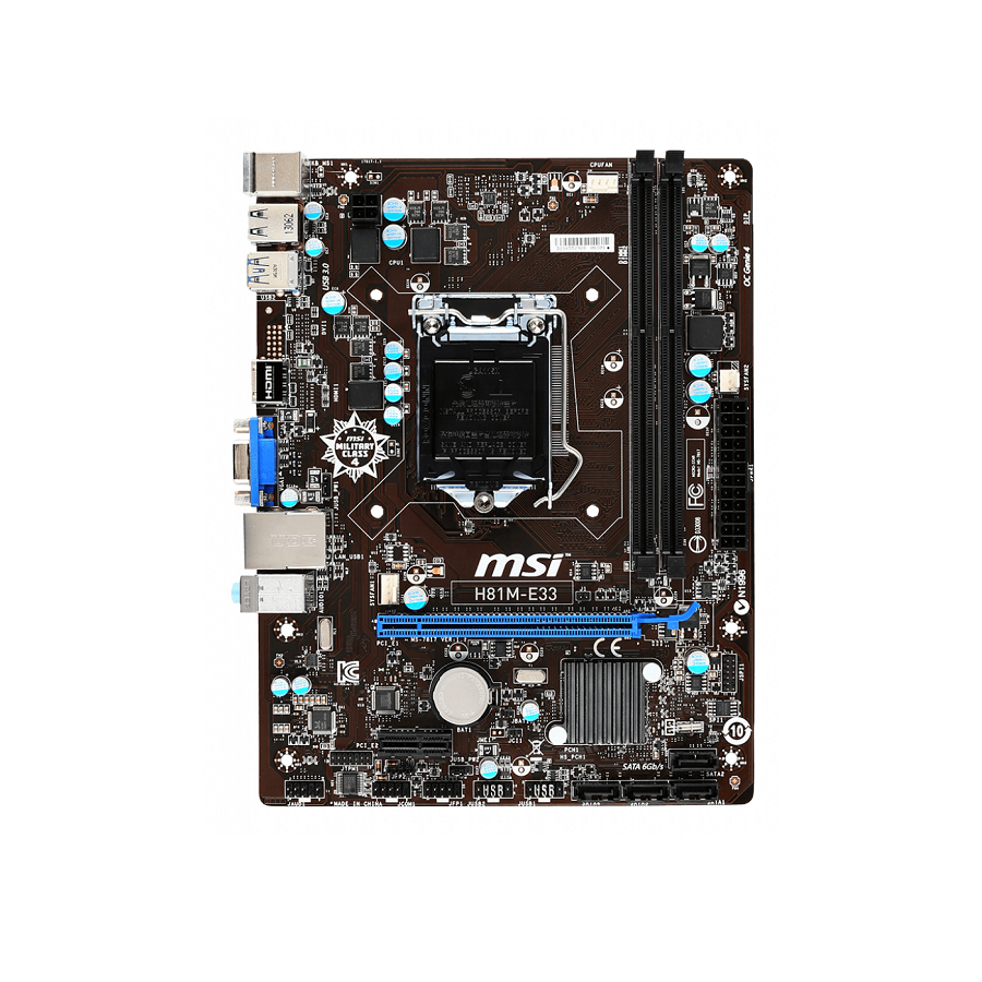
Layout
Top : mouse
Bottom: keyboard
USB2.0 ports
USB3.0 ports
DVI-D port
(for H81M-P33/
H87M-P33/ B85M-P33)
HDMI port
(for H81M-E33/
H87M-E33/ B85M-E33)
VGA port
JUSB_PW1
Top: LAN jack
Bottom: USB ports
T:Line-In
M:Line- Out
B:MIC-Int
JTPM1
JAUD1
JPWR2
SYSFAN1
PCI _E1
PCI _E2
JFP2
JUSB_PW2
JCOM1
JFP1
JUSB2
CPUFAN
JBAT1
JCI1
SATA4
JUSB1
11
SATA2
SATA3
SATA1
Advertisement
Table of Contents

Related Manuals for MSI H81M-P33 Series


Summary of Contents for MSI H81M-P33 Series
- Page 1 English Thank you for choosing the H81M-P33/ H81M-E33/ H87M-P33/ H87M-E33/ B85M- P33/ B85M-E33 Series (MS-7817 v1.X) Micro-ATX motherboard. The H81M-P33/ H81M-E33/ H87M-P33/ H87M-E33/ B85M-P33/ B85M-E33 Series motherboards are based on Intel H81/ H87/ B85 chipset for optimal system efficiency. Designed to...
-
Page 2: Motherboard Specifications
Motherboard Specifications ■ 4th Generation Intel Core™ i7 / Core™ i5 / Core™ i3 / ® Support Pentium / Celeron processors for LGA 1150 socket ® ® Chipset ■ Intel H81/ H87/ B85 Express Chipset ® Memory ■ 2x DDR3 memory slots supporting up to 16GB Support ■... - Page 3 Internal ■ 1x 24-pin ATX main power connector Connectors ■ 1x 4-pin ATX 12V power connector ■ 4x SATA connectors ■ 2x USB 2.0 connectors (supports additional 4 USB 2.0 ports) ■ 1x 4-pin CPU fan connector ■ 1x 4-pin system fan connector ■...
-
Page 4: Optional Specifications
Optional Specifications Name H81M-P33 H81M-E33 H87M-P33 Specification PCIe x16 slot Gen2 Gen2 Gen3 DVI-D/ HDMI DVI-D HDMI DVI-D SATA1, SATA2 SATA 6Gb/s SATA 6Gb/s SATA 6Gb/s SATA3, SATA4 SATA 3Gb/s SATA 3Gb/s SATA 6Gb/s BIOS ROM 64Mb 64Mb 128Mb RAID... -
Page 5: Back Panel
Back Panel H81M-E33/ H87M-E33/ B85M-E33 PS/2 Mouse Line-In USB 2.0 Line-Out HDMI USB 3.0 PS/2 Keyboard USB 2.0 H81M-P33/ H87M-P33/ B85M-P33 PS/2 Mouse Line-In USB 2.0 DVI-D Line-Out USB 3.0 PS/2 Keyboard USB 2.0 LAN LED Indicator LINK/ACT SPEED LED Status... -
Page 6: Cpu & Heatsink Installation
CPU & Heatsink Installation When installing a CPU, always remember to install a CPU heatsink. A CPU heatsink is necessary to prevent overheating and maintain system stability. Follow the steps below to ensure correct CPU and heatsink installation. Wrong installation can damage both the CPU and the motherboard. - Page 7 When you press down the load lever the PnP cap will automatically pop up from the CPU socket. Do not discard the PnP cap. Always replace the PnP cap if the CPU is removed from the socket. Evenly spread a thin layer of thermal paste (or thermal tape) on the top of the CPU.
-
Page 8: Memory Installation
Memory Installation Video Demonstration Watch the video to learn how to install memories at the address below. http://youtu.be/76yLtJaKlCQ Important DDR3 memory modules are not interchangeable with DDR2, and the DDR3 • standard is not backward compatible. Always install DDR3 memory modules in DDR3 DIMM slots. -
Page 9: Jpwr1~2: Atx Power Connectors
Internal Connectors JPWR1~2: ATX Power Connectors These connectors allow you to connect an ATX power supply. To connect the ATX power supply, align the power supply cable with the connector and firmly press the cable into the connector. If done correctly, the clip on the power cable should be hooked on the motherboard’s power connector. -
Page 10: Sata1~4: Sata Connectors
SATA1~4: SATA Connectors This connector is a high-speed SATA interface port. Each connector can connect to one SATA device. SATA devices include disk drives (HDD), solid state drives (SSD), and optical drives (CD/ DVD/ Blu-Ray). Video Demonstration Watch the video to learn how to Install SATA HDD. http://youtu.be/RZsMpqxythc Important •... -
Page 11: Cpufan,Sysfan1~2: Fan Power Connectors
CPUFAN,SYSFAN1~2: Fan Power Connectors The fan power connectors support system cooling fans with +12V. If the motherboard has a System Hardware Monitor chipset on-board, you must use a specially designed fan with a speed sensor to take advantage of the CPU fan control. Remember to connect all system fans. -
Page 12: Jfp1, Jfp2: System Panel Connectors
JFP1, JFP2: System Panel Connectors These connectors connect to the front panel switches and LEDs. The JFP1 connector is compliant with the Intel Front Panel I/O Connectivity Design Guide. ® When installing the front panel connectors, please use the optional M-Connector to simplify installation. -
Page 13: Jaud1: Front Panel Audio Connector
JAUD1: Front Panel Audio Connector This connector allows you to connect the front audio panel located on your computer case. This connector is compliant with the Intel Front Panel I/O Connectivity Design ® Guide. JTPM1: TPM Module Connector This connector connects to a TPM (Trusted Platform Module). Please refer to the TPM security platform manual for more details and usages. -
Page 14: Clear Cmos Jumper
JBAT1: Clear CMOS Jumper There is CMOS RAM onboard that is external powered from a battery located on the motherboard to save system configuration data. With the CMOS RAM, the system can automatically boot into the operating system (OS) every time it is turned on. If you want to clear the system configuration, set the jumpers to clear the CMOS RAM. - Page 15 PCI_E1~2: PCIe Expansion Slots The PCIe slot supports the PCIe interface expansion card. PCIe 3.0 x16 Slot PCIe 2.0 x1 Slot Important When adding or removing expansion cards, always turn off the power supply and unplug the power supply power cable from the power outlet. Read the expansion card’s documentation to check for any necessary additional hardware or software changes.
-
Page 16: Entering Bios Setup
(optional) on the motherboard to enable the system going to BIOS setup directly at next boot. Click "GO2BIOS" tab on "MSI Fast Boot" utility screen. Important Please be sure to install the “MSI Fast Boot” utility before using it to enter the BIOS setup. - Page 17 Overview After entering BIOS, the following screen is displayed. Temperature monitor Language System information Model name Virtual OC Genie Button Boot device priority bar BIOS menu selection BIOS menu selection Menu display OC Menu Important Overclocking your PC manually is only recommended for advanced users. •...
- Page 18 ▶ Current CPU/ DRAM/ Ring Frequency These items show the current frequencies of installed CPU, Memory and Ring. Read-only. ▶ CPU Ratio Mode [Auto] Selects the CPU Ratio operating mode. [Auto] This setting will be configured automatically by BIOS. [Fixed Mode] Fixes the CPU ratio.
- Page 19 ▶ Adjusted DRAM Frequency Shows the adjusted DRAM frequency. Read-only. ▶ DRAM Timing Mode [Auto] Selects the memory timing mode. [Auto] DRAM timings will be determined based on SPD (Serial Presence Detect) of installed memory modules. [Link] Allows user to configure the DRAM timing manually for all memory channel.
- Page 20 your overclocked processor to lock up. ▶ CPU Features Press <Enter> to enter the sub-menu. ▶ Hyper-Threading Technology [Enabled] The processor uses Hyper-Threading technology to increase transaction rates and reduces end-user response times. Intel Hyper-Threading technology treats the multi cores inside the processor as multi logical processors that can execute instructions simultaneously.
- Page 21 [Disabled] Enables the requested cache line only. ▶ CPU AES Instructions [Enabled] Enables or disables the CPU AES (Advanced Encryption Standard-New Instructions) support. This item appears when a CPU supports this function. [Enabled] Enables Intel AES support. [Disabled] Disables Intel AES support. ▶...
- Page 22 Note: The following items will appear when "Intel Turbo Boost " is enabled. ▶ Long Duration Power Limit (W) [Auto] Sets the long duration TDP power limit for CPU in Turbo Boost mode. ▶ Long Duration Maintained (s) [Auto] Sets the maintaining time for "Long duration power Limit(W)". ▶...