
Related Manuals for Honeywell Gamewell FCI GFPS-9


Summary of Contents for Honeywell Gamewell FCI GFPS-9
- Page 1 GFPS-9 Supplementary Notification Appliance Circuit Module Installation Manual Part Number: 9001-0024 Rev: N 9001-0024:N ECN 17-0298...
-
Page 3: Table Of Contents
Contents Section 1 Introduction ..............................1 Section 2 UL Requirements ..........................1 Section 3 System Overview ..........................2 Terminal Descriptions and Electrical Ratings ................2 Signal Input Terminals ......................... 2 Notification Appliance Circuit Terminals ..................3 Section 4 Installation ..............................4 Mounting ............................4 4.1.1 Preventing Water Damage ....................5 Wire Routing .......................... - Page 4 GFPS-9 Supplementary Notification Appliance Circuit Installation Manual Section 5 Sample Applications ........................17 Notification Power Applications ....................17 Non-Resettable Power Application ....................19 Door Holder Application ......................20 Section 6 Troubleshooting ..........................20 LEDs ............................20 Trouble Conditions ........................21 Earth Fault Resistance ......................22 Removing and Replacing the Control Panel ................22 6.4.1 Removing the Control Panel ....................22 6.4.2 Replacing the Control Panel ....................23 Appendix A...
-
Page 5: Introduction
Introduction Section 1 Introduction The GFPS-9 is a notification appliance circuit and auxiliary power expander that provides up to 9 amps of filtered, 24 volt power for powering notification appliances and auxiliary devices. The GFPS-9 provides its own AC power connection, battery charging circuit, and battery connections. Used with security and fire alarm control panels, the GFPS-9 enables you to connect and distribute power to many more devices than your panel may normally allow. -
Page 6: System Overview
9001-0024 Section 3 System Overview CAUTION Each output circuit is rated at 3 amps. DO NOT OVERLOAD. Overloading a circuit will cause it to shut down (power limit). The circuit will automatically reset once you remove the overload condition. Terminal Descriptions and Electrical Ratings Terminal # Description Ratings... -
Page 7: Notification Appliance Circuit Terminals
GFPS-9 Supplementary Notification Appliance Circuit Installation Manual main panel to the GFPS-9. See Figure 4-2 for more details. The main panel supervises its notification appliance circuits used for communicating with the GFPS-9 the same way it supervises ordinary notification appliance circuits. The signal inputs on the GFPS-9 monitor the polarity of the voltage coming from the main panel’s notification appliance circuits to determine when to operate the notification appliance circuits on the GFPS-9. - Page 8 9001-0024 For Option: These Inputs: Control These Outputs: Input 1 or Outputs 1, 2, 3, and 4 Class B ANSI temporal- Input 2 coded circuits Input 1 Outputs 1 and 2 Class B circuits Input 2 Outputs 3 and 4 Class B circuits Input 1 Output 1...
-
Page 9: Installation
GFPS-9 Supplementary Notification Appliance Circuit Installation Manual Section 4 Installation Before installing the GFPS-9, the AC input must first be wired into the building’s main electrical power through the TB1 terminals (see Figure 4-2). Shut off the electrical power to the GFPS-9, and then complete the general installation of the GFPS-9 using the information in this section. -
Page 10: Current Requirements (Standby And Alarm)
9001-0024 the switching power supply circuit. Note: The use of this knock out will reduce the number and/or size of batteries this cabinet can contain. Evaluation of space is important before using. Figure 4-1 Sample Wire Routing Ground fault and wire to wire short impedance to any terminal is 0 Ω. Current Requirements (Standby and Alarm) 4.3.1 Current Drawn From Host Panel... - Page 11 GFPS-9 Supplementary Notification Appliance Circuit Installation Manual See Section 4.7 for battery installation. The following is the maximum current draw from the auxiliary power terminals for standby calculations. These currents assume 24 or 60 hours of standby time, followed by 5 minutes of maximum alarm current. •...
- Page 12 9001-0024 Table 4-2: Battery Calculation Worksheet Number of Standby Alarm Device Current per Device Devices Current Current For each device use this formula: This column X This column Current per number of devices. GFPS-9 Distributed Power Module Standby: 75 mA 75 mA Alarm: 205 mA...
-
Page 13: Connecting The Gfps-6 To A Control Panel
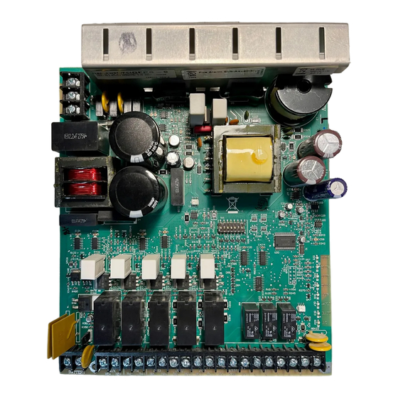
GFPS-9 Supplementary Notification Appliance Circuit Installation Manual Connecting the GFPS-9 to a Control Panel Figure 4-2 shows the general layout of the GFPS-9 PC board. This section also provides specific wiring details for accessories. Figure 4-2 The Model GFPS-9 PC Board Layout Consult the installation manual for specific wiring information for the control panel being used. -
Page 14: Notification Appliance Wiring
9001-0024 A typical application of the trouble relay is to connect the GFPS-9 normally closed (N.C.) contacts in series with the EOL supplied with the fire alarm control panel. This will cause a trouble on the fire alarm control panel when the GFPS-9 opens its trouble contacts. -
Page 15: Class B Supervised Wiring
GFPS-9 Supplementary Notification Appliance Circuit Installation Manual twist two conductors together. Figure 4-4 Class A Supervised Input/Output Connections 4.5.2 Class B Supervised Wiring Figure 4-5 shows how to wire for Class B input and output supervision. Use in/out wiring methods for proper supervision (Refer to the Appendix for notification appliances approved for use with the GFPS-9.) Class B Output Notification Circuits Figure 4-5 shows four, 1.5 A devices wired as Class B. -
Page 16: Class B Supervised Input Circuits
9001-0024 Class B Supervised Input Circuits Figure 4-5 shows Class B supervised wiring from a fire alarm control panel to the GFPS-9. Use an EOL resistor as shown to enable notification appliance circuit input supervision. Some panels use EOLs that have a different value from the 4.7k ohm EOL resistor used by the GFPS-9. In this case, the EOL must be UL listed for the fire alarm control panel (not the GFPS-9). -
Page 17: Dip Switch Settings
GFPS-9 Supplementary Notification Appliance Circuit Installation Manual Connect the red wire from the Battery + terminal to the positive (+) side of battery #1. Figure 4-6 Battery Connection DIP Switch Settings A 7-position DIP switch on the GFPS-9 board allows you to select the following: •... -
Page 18: Input/Output Configurations That Select Ansi Temporal-Coded Outputs
9001-0024 you must remove both the AC power and the battery to make the GFPS-9 recognize the new settings. Figure 4-7 Setting DIP Switches 1-3 Figure 4-8 Setting DIP Switches 1-3 (Continued) Note: For 100 mS input signal debounce with no synchronization DIP switches 6 and 7 must be turned On. 4.8.1.1 Input/Output Configurations That Select ANSI Temporal-Coded Outputs... -
Page 19: Selecting Synchronized Output Configurations
GFPS-9 Supplementary Notification Appliance Circuit Installation Manual configurations before and after the addition of this feature. Input/Output Relationship for ANSI Standard GFPS-9 Input to Output Relationship Temporal-coded Options With this new feature, a steady signal can produce the pattern shown above for panels not previously able to do Note: The GFPS-9 can also produce temporal patterns if the inputs are non-ANSI temporal configurations. -
Page 20: Selecting Synchronized Gentex Configurations
9001-0024 4.8.2.2 Selecting Synchronized Gentex Configurations To select the input/outputs for Gentex synchronized appliances, set the DIP switches as shown in Figure 4-10. Figure 4-10 Gentex Synchronized Configurations 4.8.2.3 Selecting Synchronized System Sensor Configurations To select the input/outputs for System Sensor synchronized appliances, set the DIP switches as shown in Figure 4-11. -
Page 21: Selecting Synchronized Amseco Configurations
GFPS-9 Supplementary Notification Appliance Circuit Installation Manual 4.8.2.5 Selecting Synchronized AMSECO Configurations To select the input/outputs for AMSECO synchronized appliances, set the DIP switches as shown in Figure 4-13. Figure 4-13 AMSECO Synchronized Configurations 4.8.3 Setting the Loss of AC Delay Normal selection for reporting loss of AC is 3 hours. -
Page 22: Sample Applications
9001-0024 Section 5 Sample Applications The drawings in this section show various GFPS-9 configurations, including “daisy-chaining”. Notification Power Applications GFPS-9 Local Fire Alarm Control Panel Figure 5-1 Input 1 Activates All Four Outputs GFPS-9 Local Fire Alarm Control Panel Figure 5-2 Input 1 Activates NACs 1 and 2; Input 2 Activates NACs 3 and 4 5-18... - Page 23 GFPS-9 Supplementary Notification Appliance Circuit Installation Manual Note: When multiple power supplies are used with one control unit they will not sync with each other GFPS-9 Local Fire Alarm Control Panel GFPS-9 Figure 5-3 One Control Activating Two GFPS-9s GFPS-9 Local Fire Alarm Control Panel GFPS-9...
-
Page 24: Non-Resettable Power Application
9001-0024 GFPS-9 Local Fire Alarm GFPS-9 Control Panel GFPS-9 Figure 5-5 Each Control NAC Activates Five Output NACs Non-Resettable Power Application The GFPS-9 provides a dedicated 3 A auxiliary power output that you can select as non-resettable (output is always on). See Section 4.8.4 for setting the auxiliary power. If you need more than 3 A, wire the inputs as shown in Figure 5-6. -
Page 25: Door Holder Application
GFPS-9 Supplementary Notification Appliance Circuit Installation Manual Door Holder Application In a typical door holder application, the door holder power must be interrupted to close all fire doors under the following conditions: • Any active alarm condition. • AC power failure (to conserve battery power). To close the fire doors in these situations, wire an N.C. -
Page 26: Trouble Conditions
9001-0024 Color Description BATT Yellow When ON, a low battery condition exists. Green When OFF, there is no AC power to the unit. Under normal conditions, this LED is ON to indicate the presence of AC power. See Figure 4-2 for locations of LEDs. Trouble Conditions Trouble Condition What Happens... -
Page 27: Earth Fault Resistance
GFPS-9 Supplementary Notification Appliance Circuit Installation Manual Earth Fault Resistance Table 6-1 lists the earth fault resistance detection for each applicable terminal on the FACP. Table 6-1: Earth Fault Resistance Values by Terminal Terminal Value Function Terminal Label Number (in kohms) Auxiliary Devices Notification Appliance OUT4... -
Page 28: Replacing The Control Panel
9001-0024 Remove the two heat sink screws. The heat sink screws are located on the top of the cabinet. See Figure 6-1. Figure 6-1 Mounting Screw Locations Remove the four chassis mounting screws. See Figure 6-1 for chassis screw locations. Carefully remove the control panel. -
Page 29: Ul Listed Notification Appliances
9001-0024 Appendix A UL Listed Notification Appliances For proper operation, you must use polarized devices with a Model 7628 4.7k ohm EOL resistor on each circuit. All supervised notification appliances used with the GFPS-9 must be polarized. Note: Not all devices can use the Sync feature, be sure to check Table A-1 to ensure the device you have chosen will work with this feature. - Page 30 GFPS-9 Supplementary Notification Appliance Circuit Installation Manual Table A-1: Compatible Notification Appliances Manufacturer Model Audio Visual Type Vibrating Bell Vibrating Bell Single Stroke Bell 2700 -M. -R, -T, -Y, -Z Strobe 2701 Series Strobe 2705 Series Strobe 2820 Snyc Temporal Horn/Strobe 2821 Snyc Temporal Horn/Strobe 2824...
- Page 31 9001-0024 UL Listed Notification Appliances Table A-1: Compatible Notification Appliances Manufacturer Model Audio Visual Type 5378 8-Tone Horn/Strobe 5383 8-Tone Horn/Strobe with Sync Strobe 5386 8-Tone Horn/Strobe with Sync Strobe 5387 8-Tone Horn/Strobe with Sync Strobe 5388 8-Tone Horn/Strobe with Sync Strobe 5508 Single Gang Sync Strobe 5509...
- Page 32 GFPS-9 Supplementary Notification Appliance Circuit Installation Manual Table A-1: Compatible Notification Appliances Manufacturer Model Audio Visual Type S2415-FC Strobe S241575-FC Strobe S2430-FC Strobe 130-3117C Mini Horn 130-3147C Mini Horn BLV-6 Vibrating Bell BLV-10 Vibrating Bell BLVCH Vibrating Chime H12/24-FC Horn H12/24W-FC Horn H12/24K-FC...
- Page 33 9001-0024 UL Listed Notification Appliances Table A-1: Compatible Notification Appliances Manufacturer Model Audio Visual Type GEC-24-15 Horn/Strobe GEC-24-30 Horn/Strobe GEC-24-60 Horn/Strobe GEC-24-75 Horn/Strobe GEC-24-177 Horn/Strobe Gentex GEC-24-110 Horn/Strobe GEC-24-15/75 Horn/Strobe GX91 MiniHorn Steady Tone GX93 MiniHorn Temporal Tone HG124 Horn HS24-15 Horn/Strobe HS24-30...
- Page 34 GFPS-9 Supplementary Notification Appliance Circuit Installation Manual Table A-1: Compatible Notification Appliances Manufacturer Model Audio Visual Type Chime Chime CHSR 2-Wire Chime/Strobe CHSW 2-Wire Chime/Strobe Horn Horn Horn Horn WHT Wall 4x4 Horn Red Wall 4x4 HGRL Horn Red Wall 2x4 HGWL Horn WHT Wall 2x4 CHWL...
- Page 35 9001-0024 UL Listed Notification Appliances Table A-1: Compatible Notification Appliances Manufacturer Model Audio Visual Type 4-Wire Horn/Strobe PC4W 4-Wire Horn/Strobe P4WH 4-Wire Horn/Strobe High Candela PC4WH 4-Wire Horn/Strobe High Candela P4RK 4-Wire Horn/Strobe PC4RK 4-Wire Horn/Strobe P4RHK 4-Wire Horn/Strobe High Candela PC4RHK 4-Wire Horn/Strobe High Candela PC4RH...
- Page 36 GFPS-9 Supplementary Notification Appliance Circuit Installation Manual Table A-1: Compatible Notification Appliances Manufacturer Model Audio Visual Type SCRHK Strobe High Candela SRL, SRL-P, SRL-SP* Strobe Red Wall 4x4 SWL, SWL-P, SWL-ALERT Strobe White Wall 4x4 SWL-CLR-ALERT* SCRL Strobe Red Ceil 4x4 SCWL Strobe White Ceil 4x4 System...
- Page 37 9001-0024 UL Listed Notification Appliances Table A-1: Compatible Notification Appliances Manufacturer Model Audio Visual Type HS-24 Horn HS4-241575W Horn/Strobe HS4-24MCW Horn/Strobe HS4-24MCWH Horn/Strobe HS4-24MCC Horn/Strobe MIZ-24S Mini Horn Strobe MT-121575W MultitoneHorn Strobe MT-241575W Multitone Horn Strobe MT-24MCW Multitone Horn Strobe MTWP-2475W Multitone Horn Strobe MTWP-2475C...
- Page 38 GFPS-9 Supplementary Notification Appliance Circuit Installation Manual Table A-1: Compatible Notification Appliances Manufacturer Model Audio Visual Type RSSR-2475W Strobe RSSR-2475C Strobe RSSR-24110C Strobe RSSA-24110W Strobe RSSB-24110W Strobe RSSG-24110W Strobe RSSR-24110W Strobe RSSA-24MCC Multi-Cd Strobe RSSB-24MCC Multi-Cd Strobe RSSG-24MCC Multi-Cd Strobe RSSR-24MCC Multi-Cd Strobe RSSWPA-2475W...
-
Page 39: Manufacturer Warranties And Limitation Of Liability
Manufacturer Warranties and Limitation of Liability Manufacturer Warranties. Subject to the limitations set forth herein, Manufacturer warrants that the Products manufactured by it in its Northford, Connecticut facility and sold by it to its authorized Distributors shall be free, under normal use and service, from defects in material and workmanship for a period of thirty six months (36) months from the date of manufacture (effective Jan. - Page 42 Gamewell-FCI 12 Clintonville Road Northford, CT 06472-1653 USA 203-484-7161 fax 203-484-7118 www.gamewell-fci.com...