Bosch CLIMATE 5000 VRF HWRC Installation & User Manual
Wired remote controller
Hide thumbs
Also See for CLIMATE 5000 VRF HWRC:
- Installation manual (36 pages) ,
- Installation & user manual (24 pages) ,
- Installation and user manual (16 pages)

Related Manuals for Bosch CLIMATE 5000 VRF HWRC


Summary of Contents for Bosch CLIMATE 5000 VRF HWRC
- Page 1 CLIMATE 5000 VRF Wired Remote Controller HWRC Installation-user manual Thank you very much for purchasing our air conditioner, Before using your air conditioner, please read this manual carefully and keep it for future reference.
- Page 2 2 | INSTALLATION & OWNER’S MANUAL INSTALLATION & OWNER’S MANUAL Wired Remote Controller • This manual gives detailed description of the precautions that should be brought to your attention during operation. • In order to ensure correct service of the wired controller please read this manual carefully before using the unit.
-
Page 3: Table Of Contents
Contents | 3 Contents SAFETY PRECAUTIONS ............4 OTHER PRECAUTIONS ............5 INSTALLATION PROCEDURE ..........8 WIRING FIGURE OF THE WIRED REMOTE CONTROLLER CONNECT WITH THE INDOOR UNIT ........11 MAIN PARAMETERS ............16 MAIN FUNCTIONS ..............16 NAMES AND FUNCTIONS OF KEYS ........17 OPERATION METHOD ............19 CLIMATE 5000 VRF 6720844816 (2015/07) -
Page 4: Safety Precautions
4 | SAFETY PRECAUTIONS SAFETY PRECAUTIONS It indicates compulsory implementation. The compulsory The following contents are stated on the product and subject-matter is indicated in the icon the operation manual, including usage, precautions or by images or characters aside. against personal harm and property loss, and the methods of using the product correctly and safely. -
Page 5: Other Precautions
OTHER PRECAUTIONS | 5 OTHER PRECAUTIONS Installation Location Do not install the unit in a place with much oil, steam, sulfi de gas. Otherwise, the product may deform and fail. Preparation before installation 1. Check whether the following assemblies are complete. Name Qty. - Page 6 6 | OTHER PRECAUTIONS 2. Prepare the following assemblies on the site. Name Qty. Remarks General electrical box size, Electrical box embedded in the wall in advance. PVVR-0.5mm2x4,embedded in the wall in 4-core shielding wire advance. Embedded in the wall in advance, Wiring tube(insulation casing) the longest is 12M.
- Page 7 OTHER PRECAUTIONS | 7 Notice to installation of wired remote controller 1. This manual contains information about the procedure of installing the controller. 2. The circuit of the wired remote controller is low voltage circuit, Never connect it with a 220V/380V circuit or put it into a same Wiring Tube with the circuit and the interval must be more than 300~500mm.
-
Page 8: Installation Procedure
8 | INSTALLATION PROCEDURE INSTALLATION PROCEDURE Principle diagram of wired remote controller: Wired Remote Controller 4-Core Shield Cable, the length is decided by installation Indoor Unit display panel Indoor Unit Fig.3.1 Installation instruction fi gure: Attached connecting wires for the display panel 4-core shielding wire Display panel embedded in the wall... - Page 9 INSTALLATION PROCEDURE | 9 Fig.3.4 Fig.3.5 CLIMATE 5000 VRF 6720844816 (2015/07)
- Page 10 10 | INSTALLATION PROCEDURE 1. Insert the 4-core plug of the connecting wires for the signal receiving panel into the 4-core socket of the signal receiving panel. (Fig.3.2) 2. Connect the other terminal of the connecting wires for the signal receiving panel with the embed-ded 4-core shielding wire, and ensure the connection are reliable and fi...
-
Page 11: Wiring Figure Of The Wired Remote Controller Connect With The Indoor Unit | 11
WIRING FIGURE OF THE WIRED REMOTE CONTROLLER CONNECT WITH THE INDOOR UNIT | 11 WIRING FIGURE OF THE WIRED REMOTE CONTROLLER CONNECT WITH THE INDOOR UNIT 1. Wiring fi gure of the wire controller connect with the four-way cassette type indoor unit Indoor unit electric Plane of indoor unit controlling box... - Page 12 12 | WIRING FIGURE OF THE WIRED REMOTE CONTROLLER CONNECT WITH THE INDOOR UNIT 2. Wiring fi gure of the wire controller connect with the courtyard-style duct type indoor unit Indoor unit electric controlling box Plane of indoor unit Electric controlling boxs’...
- Page 13 WIRING FIGURE OF THE WIRED REMOTE CONTROLLER CONNECT WITH THE INDOOR UNIT | 13 3. Wiring fi gure of the wire controller connect with the high-static pressure duct type indoor unit Indoor unit electric controlling box Electric controlling boxs’ plug CN10 Main board Display panel Back of the...
- Page 14 14 | WIRING FIGURE OF THE WIRED REMOTE CONTROLLER CONNECT WITH THE INDOOR UNIT 4. Wiring fi gure of the wire controller connect with the wall hanging type indoor unit Indoor unit electric controlling box Plane of indoor unit Electric controlling boxs’...
- Page 15 WIRING FIGURE OF THE WIRED REMOTE CONTROLLER CONNECT WITH THE INDOOR UNIT | 15 5. Wiring fi gure of the wire controller connect with the stand-hanging type indoor unit Indoor unit electric controlling box Plane of indoor unit Electric controlling boxs’...
-
Page 16: Main Parameters
16 | MAIN PARAMETERS MAIN PARAMETERS MODEL HWRC Voltage input DC +5V Ambient temperature range -5~43°C Ambient humidity range RH40%~RH90% MAIN FUNCTIONS 1. Set HEAT/ COOL operation mode; 2. Set fan speed; 3. Temperature setting range: 17°C-30°C; 4. Power down memory function; 5. -
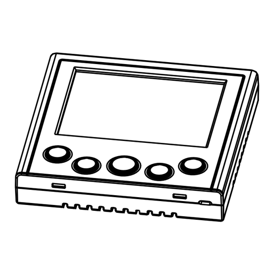
Page 17: Names And Functions Of Keys | 17
NAMES AND FUNCTIONS OF KEYS | 17 NAMES AND FUNCTIONS OF KEYS CLIMATE 5000 VRF 6720844816 (2015/07) - Page 18 18 | NAMES AND FUNCTIONS OF KEYS FUNCTION ON/OFF On/Off the unit FAN SPEED Select fan speed SET TEMP UP Increase setting temperature SET TEMP DOWM Decrease setting temperature 26°C SHORTCUT Quickly set the operation tempareture to 26°C 6720844816 (2015/07) CLIMATE 5000 VRF...
-
Page 19: Operation Method | 19
OPERATION METHOD | 19 OPERATION METHOD ON/OFF 1. When the unit is turned off , press the ON/OFF button, the unit will be turned on and the LCD screen of the wired remote controller on. 2. When the unit is turned on, press the ON/OFF button, the unit will be turned off and the LCD screen of the wired remote controller off... - Page 20 Bosch Thermotechnik GmbH Junkersstraße 20-24 D-73249 Wernau www.bosch-thermotechnology.com...